EP1559841B1 - Verfahren zur Installation und/oder zum Betrieb eines Abwassersammelschachts - Google Patents
Verfahren zur Installation und/oder zum Betrieb eines Abwassersammelschachts Download PDFInfo
- Publication number
- EP1559841B1 EP1559841B1 EP04028908A EP04028908A EP1559841B1 EP 1559841 B1 EP1559841 B1 EP 1559841B1 EP 04028908 A EP04028908 A EP 04028908A EP 04028908 A EP04028908 A EP 04028908A EP 1559841 B1 EP1559841 B1 EP 1559841B1
- Authority
- EP
- European Patent Office
- Prior art keywords
- duration
- measurement
- sewerage
- pumping time
- pump
- Prior art date
- Legal status (The legal status is an assumption and is not a legal conclusion. Google has not performed a legal analysis and makes no representation as to the accuracy of the status listed.)
- Expired - Lifetime
Links
- 238000000034 method Methods 0.000 title claims description 13
- 238000009434 installation Methods 0.000 title claims description 7
- 239000010865 sewage Substances 0.000 title description 35
- 238000005259 measurement Methods 0.000 claims description 29
- 238000005086 pumping Methods 0.000 claims description 11
- 238000001514 detection method Methods 0.000 claims description 8
- 238000012423 maintenance Methods 0.000 claims description 2
- 239000002351 wastewater Substances 0.000 abstract description 29
- 239000002360 explosive Substances 0.000 abstract description 6
- XLYOFNOQVPJJNP-UHFFFAOYSA-N water Substances O XLYOFNOQVPJJNP-UHFFFAOYSA-N 0.000 abstract description 6
- 239000012528 membrane Substances 0.000 description 5
- 231100001261 hazardous Toxicity 0.000 description 3
- 238000004382 potting Methods 0.000 description 3
- 150000001875 compounds Chemical class 0.000 description 2
- 238000004880 explosion Methods 0.000 description 2
- 239000000203 mixture Substances 0.000 description 2
- UAOUIVVJBYDFKD-XKCDOFEDSA-N (1R,9R,10S,11R,12R,15S,18S,21R)-10,11,21-trihydroxy-8,8-dimethyl-14-methylidene-4-(prop-2-enylamino)-20-oxa-5-thia-3-azahexacyclo[9.7.2.112,15.01,9.02,6.012,18]henicosa-2(6),3-dien-13-one Chemical compound C([C@@H]1[C@@H](O)[C@@]23C(C1=C)=O)C[C@H]2[C@]12C(N=C(NCC=C)S4)=C4CC(C)(C)[C@H]1[C@H](O)[C@]3(O)OC2 UAOUIVVJBYDFKD-XKCDOFEDSA-N 0.000 description 1
- 244000287680 Garcinia dulcis Species 0.000 description 1
- 238000004873 anchoring Methods 0.000 description 1
- 238000010276 construction Methods 0.000 description 1
- 230000001419 dependent effect Effects 0.000 description 1
- 238000012806 monitoring device Methods 0.000 description 1
- 238000012544 monitoring process Methods 0.000 description 1
Images


Classifications
-
- E—FIXED CONSTRUCTIONS
- E03—WATER SUPPLY; SEWERAGE
- E03F—SEWERS; CESSPOOLS
- E03F5/00—Sewerage structures
- E03F5/22—Adaptations of pumping plants for lifting sewage
Definitions
- the invention relates to a sewer manhole with explosive or non-hazardous atmosphere above the sewage level, wherein in the wastewater at least one sewage pump is immersed, the sewage pump can be switched on depending on an upper level of the sewage and after a delivery time off again.
- Such a sewage collection shaft is known from the prior art.
- sewage collection shafts or their operation guidelines must be complied with, according to which it must be avoided that mechanically moving parts come into contact with the air-gas mixture of a potentially explosive atmosphere. So it must be avoided in the discharge of wastewater, that moving parts of the sewage pump come into contact with the explosive atmosphere by excessive drop of the sewage level. This means that the sewage pump may not be switched off too late.
- DE 39 18 294 A1 describes a device for monitoring sewage pumping stations.
- the wastewater pump is connected to a monitoring device that continuously monitors the pump output and compares this output with previously determined reference values.
- a dry run protection device for sewage pumps is known.
- the device has two modes which are used depending on the amount of wastewater.
- the pumps are only switched on and their running time compared with a fixed time. If the pump runs too long, the system will run dry and an alarm will sound. With a strong inflow is pumped as long as a correspondingly provided membrane switch signals the concern of a Drukkes. If there is no pressure left, the system is switched off.
- the detection devices In order to achieve that on the one hand after reaching a maximum waste water level, the detection devices completely be released, but on the other hand is excluded that the sewage pump is also exposed, it is necessary in the installation of conventional sewer manholes to determine the optimal delivery time of the sewage pump by an installer using a stopwatch.
- the optimal delivery time depends, among other things, on the back pressure against which the sewage pump removes the wastewater. If a low back pressure is present, the delivery time is shorter, with higher back pressures the delivery time increases. An inflow of wastewater when the pump is activated also influences the optimum delivery time.
- the procedure described is disadvantageous for several reasons. First, the delivery time must be determined manually and the pump must be programmed accordingly. In addition, it may happen that during the installation of the sewer manhole counterpressure from "zero" to "maximum” is not applicable, so that the determination of the delivery time is fraught with some uncertainty.
- the present invention has the object, a method for installation and / or 3a to operate a sewer manhole of the type assumed to be known, with the reliable and with little effort an optimal delivery time can be determined.
- a pump control, a timing device and a pressure sensing device is provided, wherein with the timing device a time period between the detection of two different heights of the waste water level corresponding, predetermined pressure values can be measured, wherein depending on the measured time duration, the delivery time of the pump control can be predetermined.
- the wastewater collection shaft according to the invention allows the determination of an optimal delivery time without manual intervention.
- the time required to lower the wastewater level by a certain amount is determined and the delivery time is determined on the basis of this time period.
- the beginning and the end of the mentioned time period correspond to the detection of predetermined pressure values which correspond to different heights of the wastewater level.
- the delivery time can be specified during installation and / or maintenance of the wastewater collection shaft. This funding period Can be maintained for further operation of the sewer manhole without changes.
- the delivery time can correspond to a multiple of the measured time duration.
- the delivery time can be varied as a function of a respectively last measured time duration. This makes it possible, without manual intervention, to be able to adapt the delivery time in accordance with a changing counterpressure applied to the sewage pump. In this case, successive measurements can also be taken into account pro rata.
- the pressure sensing device may include a dynamic pressure bell and / or a back pressure hose. This has the advantage that no electrical components come into contact with the potentially explosive atmosphere.
- the pressure-sensing device may have a dynamic pressure sensor, a differential pressure sensor and / or a pressure switch, in particular a pressure switch with hysteresis.
- These sensors or switches may be connected downstream of the dynamic pressure gate and / or the back pressure hose, wherein the switches or sensors should be arranged in a non-hazardous environment.
- the pressure detection device or the switches or sensors can communicate with the pump controller electrically or via radio.
- the use of a radio link has the advantage that the pump control also at one distant location of the sewer manhole is positionable.
- the invention further relates to a method for operating a sewer manhole.
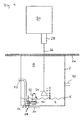
- a wastewater collecting shaft 2 is provided, which is arranged below a cover 2a. Within the sewage collection shaft 2 waste water 4 can be collected, which forms a waste water level 6. The space 8 above the water level 6 is at risk of explosion.
- the waste water 4 is fed to the sewage collecting shaft 2 through a supply line 10.
- a supply line 10 In the collected wastewater 4 at least partially submerged sewage pump 12 a. This has a spiral housing 14, which should always be immersed in the wastewater 4.
- the pump 12 is over a Flange 16 mounted in an anchoring area 18 in the ground 20.
- the pump 12 is followed by a drain line 22, wherein the pressure applied in the drain line back pressure can vary.
- a dynamic pressure bell 24 is arranged, which communicates via a dynamic pressure hose 26 with a switching / sensor device 28 in connection.
- the device 28 communicates with a pump controller 30.
- FIG. 2 shows a unit 28a with a hysteresis-type pressure switch corresponding to the unit 28 according to FIG.
- the unit 28a has a housing 28b which delimits an inner space 28c in which two gas-tight membranes 28d and 28e arranged adjacent to one another are provided.
- the membranes 28d and 28e define a membrane space 28f.
- a downstream switch 28 g is actuated, which is isolated via a potting compound 28 h from the housing of the adjacent pump control 30 a.
- the interior 28c of the unit 28a is connected via a housing stub 28i with the illustrated back pressure hose 26a in connection, which is connected at its lower end to the dynamic pressure bell 24a.
- an explosive mixture which is supplied via the ram pressure hose 26a to the inner space 28c, can be discharged through a laterally arranged channel 28j.
- FIG. 2 Only indicated in FIG. 2 is a second unit 28k, which corresponds in its construction to the unit 28a. With such a second unit, the sewage level 6 can be detected via another, not shown, back pressure bell. Such a second device 28k may be provided for safety reasons to provide a redundant arrangement.
- the unit 28 according to FIG. 1 is designed as a differential pressure sensor 281.
- This has a housing 28m, which is filled with a potting compound 28n.
- the housing 28m has a first housing socket 28o, which communicates via a dynamic pressure hose 26b with a dynamic pressure bell 24b.
- the housing 28m has a second housing spigot 28p against which a simple ambient pressure is applied.
- a differential pressure sensor element 28q is provided, which is suitable for detecting a differential pressure between the pressure applied to the housing connection 28p and to the housing connection 28o.
- the differential pressure sensor element 28q is connected via a downstream board 28r and via electrical lines 28s to a pump control 30b.
- the entire delivery time can now be determined, for example with the aid of a predetermined multiplier. If the pump 12 is to be turned off when reaching a water level "III", the measured time duration would have to be multiplied by a factor of "2". If a waste water level 6 denoted by "IV" is to be reached, the measured time duration would have to be multiplied by a multiplier of "3".
- the switching on of the pump 12 can also be initiated when the height "I" of the wastewater mirror 6 is reached.
- the uppermost level from which the waste water pump 12 is turned on corresponds to highest height of the heights corresponding to the predetermined pressure values.
- the turning on of the sewage pump 12 and the start of the measurement of the period between the detection of the heights "I" and "II" of the sewage mirror 6 coincide.
- the wastewater collection well 2 can be put into operation without the need for manual intervention by an installer.
- this measured time duration can be multiplied by a predetermined multiplier, for example "3", for a total delivery time of 15 seconds. to obtain.
- a predetermined multiplier for example "3”
- the pump 12 is turned off.
- the time duration of this second measurement be equal to the time duration of the first measurement, no change in the delivery time is required.
- this second measurement of the delivery time can be used as a basis. For example, in the second measurement, the time duration is 4 seconds, so that a multiplier of "3" determines a delivery time of 12 seconds in total can be. This ensures that the dynamic pressure bell 24 can be completely exposed by wastewater 4.
- the time duration of the second measurement can not be readily based on the delivery time, without the risk that too long is pumped, which could lead to an exposure of the volute casing 14 of the sewage pump 12.
- the second, longer period of time is initially taken into account only proportionally. With a freely selectable proportion factor of, for example, 50% with a measured first time duration of 5 seconds and a measured second time duration of 10 seconds, a new delivery time would initially be based on a duration of only 7.5 seconds. These 7.5 seconds are used to determine the funding period with the o.g. Multiplier multiplied.
- a shorter time duration is then measured in a subsequent, third measurement, this can, as described above, again be based directly on the new delivery time. If the time duration of the third measurement is equal to the time duration of the second measurement, this can be maintained. If the time duration of the third measurement is longer than that of the second measurement, for example 12.5 sec., The time duration of the second and the third measurement can again be taken into account proportionately, which with a proportional factor of 50% to a delivery time of 10 sec. This funding period would again be multiplied by the predetermined multiplier.
Landscapes
- Health & Medical Sciences (AREA)
- Life Sciences & Earth Sciences (AREA)
- Engineering & Computer Science (AREA)
- Hydrology & Water Resources (AREA)
- Public Health (AREA)
- Water Supply & Treatment (AREA)
- Control Of Positive-Displacement Pumps (AREA)
- Sewage (AREA)
- Centrifugal Separators (AREA)
- Structures Of Non-Positive Displacement Pumps (AREA)
- Control Of Non-Positive-Displacement Pumps (AREA)
- Pretreatment Of Seeds And Plants (AREA)
Priority Applications (1)
| Application Number | Priority Date | Filing Date | Title |
|---|---|---|---|
| PL04028908T PL1559841T3 (pl) | 2004-01-29 | 2004-12-07 | Sposób instalacji i/lub eksploatacji szybu zbiorczej studzienki ściekowej |
Applications Claiming Priority (2)
| Application Number | Priority Date | Filing Date | Title |
|---|---|---|---|
| DE102004004401 | 2004-01-29 | ||
| DE102004004401A DE102004004401B8 (de) | 2004-01-29 | 2004-01-29 | Verfahren zur Installation und/oder zum Betrieb eines Abwassersammelschachts |
Publications (3)
| Publication Number | Publication Date |
|---|---|
| EP1559841A2 EP1559841A2 (de) | 2005-08-03 |
| EP1559841A3 EP1559841A3 (de) | 2007-01-24 |
| EP1559841B1 true EP1559841B1 (de) | 2008-01-23 |
Family
ID=34638795
Family Applications (1)
| Application Number | Title | Priority Date | Filing Date |
|---|---|---|---|
| EP04028908A Expired - Lifetime EP1559841B1 (de) | 2004-01-29 | 2004-12-07 | Verfahren zur Installation und/oder zum Betrieb eines Abwassersammelschachts |
Country Status (4)
| Country | Link |
|---|---|
| EP (1) | EP1559841B1 (pl) |
| AT (1) | ATE384834T1 (pl) |
| DE (2) | DE102004004401B8 (pl) |
| PL (1) | PL1559841T3 (pl) |
Cited By (1)
| Publication number | Priority date | Publication date | Assignee | Title |
|---|---|---|---|---|
| US9719241B2 (en) | 2012-12-20 | 2017-08-01 | Grundfos Holding A/S | Method for operating a wastewater pumping station |
Families Citing this family (3)
| Publication number | Priority date | Publication date | Assignee | Title |
|---|---|---|---|---|
| DE102007008692A1 (de) | 2007-02-20 | 2008-08-21 | Ksb Aktiengesellschaft | Niveauabhängige Steuerung von Pumpen |
| EP2489798A1 (de) * | 2011-02-16 | 2012-08-22 | Grundfos Management a/s | Abwasserhebeanlage |
| CN102220783B (zh) * | 2011-04-14 | 2012-10-10 | 中国市政工程中南设计研究总院 | 城市合流污水溢流和雨水径流污染控制的装置、方法和用途 |
Family Cites Families (8)
| Publication number | Priority date | Publication date | Assignee | Title |
|---|---|---|---|---|
| DE2913970A1 (de) * | 1979-04-04 | 1980-10-23 | Hubert Combe | Steuerung fuer eine abwasser- und faekalienhebeanlage |
| DE3110735C2 (de) * | 1981-03-16 | 1984-03-22 | Hubert 1000 Berlin Combé | Trockenlaufschutzvorrichtung für eine Abwasserpumpe |
| DE3311980A1 (de) * | 1983-03-30 | 1984-10-04 | Hubert 1000 Berlin Combé | Abwasserhebeanlage |
| FI80933C (fi) * | 1988-06-08 | 1990-08-10 | Sarlin Ab Oy E | Oevervakningsfoerfarande foer avlopps- pumpstation samt oevervakningsanordning foer foerverkligande av foerfarandet. |
| EP0511383B1 (en) * | 1990-01-16 | 1997-03-19 | Kabushiki Kaisha Komatsu Seisakusho | Automatic vibration method and apparatus for hydraulic excavator |
| DE69302635T2 (de) * | 1992-07-21 | 1996-10-31 | Lencioni Carlo Camaiore | Vorrichtung zur Steuerung von Pumpen in Entwässerungsanlagen |
| FR2696424B1 (fr) | 1992-10-05 | 1994-12-23 | Europ Laitiere | Dispositif d'emballage notamment pour produit alimentaire. |
| DE19609427C2 (de) * | 1996-03-11 | 1999-04-01 | Hermann Schmelzer | Kanalüberlaufsicherung für Schachtbauwerke |
-
2004
- 2004-01-29 DE DE102004004401A patent/DE102004004401B8/de not_active Expired - Fee Related
- 2004-12-07 AT AT04028908T patent/ATE384834T1/de active
- 2004-12-07 EP EP04028908A patent/EP1559841B1/de not_active Expired - Lifetime
- 2004-12-07 PL PL04028908T patent/PL1559841T3/pl unknown
- 2004-12-07 DE DE502004006037T patent/DE502004006037D1/de not_active Expired - Lifetime
Cited By (1)
| Publication number | Priority date | Publication date | Assignee | Title |
|---|---|---|---|---|
| US9719241B2 (en) | 2012-12-20 | 2017-08-01 | Grundfos Holding A/S | Method for operating a wastewater pumping station |
Also Published As
| Publication number | Publication date |
|---|---|
| DE102004004401B4 (de) | 2006-02-02 |
| DE102004004401A1 (de) | 2005-08-25 |
| EP1559841A3 (de) | 2007-01-24 |
| DE102004004401B8 (de) | 2008-11-06 |
| PL1559841T3 (pl) | 2008-06-30 |
| ATE384834T1 (de) | 2008-02-15 |
| DE502004006037D1 (de) | 2008-03-13 |
| EP1559841A2 (de) | 2005-08-03 |
Similar Documents
| Publication | Publication Date | Title |
|---|---|---|
| EP2258949B1 (de) | Verfahren zur Ermittlung von charakteristischen Werten, insbesondere Werten , insbesondere von Parametern, eines in einer Anlage eingebundenen elektromotorisch angetriebenen Kreiselpumpenaggregates | |
| EP3791194B1 (de) | Akkustisches zustandsüberwachungsverfahren und -system für elektrische leistungskomponenten, insbesondere transformatoren | |
| EP1961963B1 (de) | Niveauabhängige Steuerung von Pumpen | |
| EP2756218B1 (de) | Verbessertes verfahren zum automatisierten ablassen von kondensat aus einem druckgassystem | |
| DE102011102336A1 (de) | Rezirkulationseinrichtung für ein Brennstoffzellensystem | |
| DE1961928B2 (de) | Vorrichtung zum Überwachen einer Rohrleitung auf Rohrbrüche | |
| EP1091197B1 (de) | Vorrichtung zur kontinuierlichen Messung des dynamischen Kraftstoffverbrauchs eines Verbrauchers | |
| EP2122177B1 (de) | Pumpenaggregat | |
| DE19515366C2 (de) | Betriebsverfahren und Steuergerät für eine Regenwassernutzungsanlage | |
| DE102004004401B4 (de) | Verfahren zur Installation und/oder zum Betrieb eines Abwassersammelschachts | |
| EP1762791A2 (de) | Behälterteil zur Abführung von Kondensat aus einem Siphon in eine Abwasserleitung | |
| EP1203851A1 (de) | Dachentwässerungsanlage und Verfahren zur Dachentwässerung | |
| DE19927365C2 (de) | Verfahren zum Steuern des Pegels beim Abpumpen eines fließfähigen Mediums mit mindestens zwei Tauchmotorpumpen | |
| DE3110735A1 (de) | Trockenlaufschutzvorrichtung fuer abwasserpumpen, insbesondere fuer hebeanlagen | |
| EP2076635B1 (de) | Verfahren und vorrichtung zur erfassung der nutzung von urinalen und zur auslösung einer automatischen spülung | |
| DE102011107817A1 (de) | Einrichtung zum Abpumpen von Flüssigkeiten | |
| EP3248850B1 (de) | Verfahren zum betrieb einer vakuumpumpe sowie vakuumpumpenanordnung | |
| DE102006024717B4 (de) | Verfahren zum Betrieb eines Drucklufthebersystems für eine Kleinkläranlage und Drucklufthebersystem | |
| DE102015009592A1 (de) | Verfahren und Vorrichtung zum Überwachen eines Abscheiders | |
| EP1311418A1 (de) | Verfahren, computerprogramm und vorrichtung zur überwachung einer unterdruckeinrichtung | |
| WO2011012304A1 (de) | Steuerung und steurungsverfahren zum schutz von manuell einschaltbaren elektrischen wasserpumpen | |
| DE102010036916B4 (de) | Rückstausperre für eine Abwasserleitung und Verfahren zum Betreiben einer derartigen Rückstausperre | |
| DE3443130A1 (de) | Einrichtung zur ueberwachung des wasserstandes im kanalisationssystem eines gebaeudes | |
| DE102006041482B3 (de) | Verfahren zum Spülen einer Druckrohrleitung und Abwasserfördervorrichtung | |
| EP4261413A1 (de) | Vorrichtung und verfahren zum ermitteln eines zustandes, insbesondere eines verschleisszustandes, einer verdrängereinheit |
Legal Events
| Date | Code | Title | Description |
|---|---|---|---|
| PUAI | Public reference made under article 153(3) epc to a published international application that has entered the european phase |
Free format text: ORIGINAL CODE: 0009012 |
|
| AK | Designated contracting states |
Kind code of ref document: A2 Designated state(s): AT BE BG CH CY CZ DE DK EE ES FI FR GB GR HU IE IS IT LI LT LU MC NL PL PT RO SE SI SK TR |
|
| AX | Request for extension of the european patent |
Extension state: AL BA HR LV MK YU |
|
| PUAL | Search report despatched |
Free format text: ORIGINAL CODE: 0009013 |
|
| AK | Designated contracting states |
Kind code of ref document: A3 Designated state(s): AT BE BG CH CY CZ DE DK EE ES FI FR GB GR HU IE IS IT LI LT LU MC NL PL PT RO SE SI SK TR |
|
| AX | Request for extension of the european patent |
Extension state: AL BA HR LV MK YU |
|
| 17P | Request for examination filed |
Effective date: 20070110 |
|
| 17Q | First examination report despatched |
Effective date: 20070220 |
|
| 17Q | First examination report despatched |
Effective date: 20070220 |
|
| RTI1 | Title (correction) |
Free format text: METHOD OF INSTALLATION AND/OR WORKING OF A SEWAGE COLLECTION WELL |
|
| GRAP | Despatch of communication of intention to grant a patent |
Free format text: ORIGINAL CODE: EPIDOSNIGR1 |
|
| AKX | Designation fees paid |
Designated state(s): AT BE BG CH CY CZ DE DK EE ES FI FR GB GR HU IE IS IT LI LT LU MC NL PL PT RO SE SI SK TR |
|
| GRAS | Grant fee paid |
Free format text: ORIGINAL CODE: EPIDOSNIGR3 |
|
| GRAA | (expected) grant |
Free format text: ORIGINAL CODE: 0009210 |
|
| AK | Designated contracting states |
Kind code of ref document: B1 Designated state(s): AT BE BG CH CY CZ DE DK EE ES FI FR GB GR HU IE IS IT LI LT LU MC NL PL PT RO SE SI SK TR |
|
| REG | Reference to a national code |
Ref country code: GB Ref legal event code: FG4D Free format text: NOT ENGLISH |
|
| REG | Reference to a national code |
Ref country code: CH Ref legal event code: EP |
|
| REG | Reference to a national code |
Ref country code: IE Ref legal event code: FG4D Free format text: LANGUAGE OF EP DOCUMENT: GERMAN |
|
| REF | Corresponds to: |
Ref document number: 502004006037 Country of ref document: DE Date of ref document: 20080313 Kind code of ref document: P |
|
| REG | Reference to a national code |
Ref country code: PL Ref legal event code: T3 |
|
| NLV1 | Nl: lapsed or annulled due to failure to fulfill the requirements of art. 29p and 29m of the patents act | ||
| PG25 | Lapsed in a contracting state [announced via postgrant information from national office to epo] |
Ref country code: IS Free format text: LAPSE BECAUSE OF FAILURE TO SUBMIT A TRANSLATION OF THE DESCRIPTION OR TO PAY THE FEE WITHIN THE PRESCRIBED TIME-LIMIT Effective date: 20080523 Ref country code: ES Free format text: LAPSE BECAUSE OF FAILURE TO SUBMIT A TRANSLATION OF THE DESCRIPTION OR TO PAY THE FEE WITHIN THE PRESCRIBED TIME-LIMIT Effective date: 20080504 Ref country code: FI Free format text: LAPSE BECAUSE OF FAILURE TO SUBMIT A TRANSLATION OF THE DESCRIPTION OR TO PAY THE FEE WITHIN THE PRESCRIBED TIME-LIMIT Effective date: 20080123 |
|
| GBV | Gb: ep patent (uk) treated as always having been void in accordance with gb section 77(7)/1977 [no translation filed] | ||
| PG25 | Lapsed in a contracting state [announced via postgrant information from national office to epo] |
Ref country code: BG Free format text: LAPSE BECAUSE OF FAILURE TO SUBMIT A TRANSLATION OF THE DESCRIPTION OR TO PAY THE FEE WITHIN THE PRESCRIBED TIME-LIMIT Effective date: 20080423 |
|
| PG25 | Lapsed in a contracting state [announced via postgrant information from national office to epo] |
Ref country code: PT Free format text: LAPSE BECAUSE OF FAILURE TO SUBMIT A TRANSLATION OF THE DESCRIPTION OR TO PAY THE FEE WITHIN THE PRESCRIBED TIME-LIMIT Effective date: 20080623 Ref country code: SI Free format text: LAPSE BECAUSE OF FAILURE TO SUBMIT A TRANSLATION OF THE DESCRIPTION OR TO PAY THE FEE WITHIN THE PRESCRIBED TIME-LIMIT Effective date: 20080123 |
|
| REG | Reference to a national code |
Ref country code: IE Ref legal event code: FD4D |
|
| PG25 | Lapsed in a contracting state [announced via postgrant information from national office to epo] |
Ref country code: SE Free format text: LAPSE BECAUSE OF FAILURE TO SUBMIT A TRANSLATION OF THE DESCRIPTION OR TO PAY THE FEE WITHIN THE PRESCRIBED TIME-LIMIT Effective date: 20080423 Ref country code: DK Free format text: LAPSE BECAUSE OF FAILURE TO SUBMIT A TRANSLATION OF THE DESCRIPTION OR TO PAY THE FEE WITHIN THE PRESCRIBED TIME-LIMIT Effective date: 20080123 Ref country code: CZ Free format text: LAPSE BECAUSE OF FAILURE TO SUBMIT A TRANSLATION OF THE DESCRIPTION OR TO PAY THE FEE WITHIN THE PRESCRIBED TIME-LIMIT Effective date: 20080123 Ref country code: NL Free format text: LAPSE BECAUSE OF FAILURE TO SUBMIT A TRANSLATION OF THE DESCRIPTION OR TO PAY THE FEE WITHIN THE PRESCRIBED TIME-LIMIT Effective date: 20080123 Ref country code: IE Free format text: LAPSE BECAUSE OF FAILURE TO SUBMIT A TRANSLATION OF THE DESCRIPTION OR TO PAY THE FEE WITHIN THE PRESCRIBED TIME-LIMIT Effective date: 20080123 Ref country code: SK Free format text: LAPSE BECAUSE OF FAILURE TO SUBMIT A TRANSLATION OF THE DESCRIPTION OR TO PAY THE FEE WITHIN THE PRESCRIBED TIME-LIMIT Effective date: 20080123 |
|
| EN | Fr: translation not filed | ||
| PG25 | Lapsed in a contracting state [announced via postgrant information from national office to epo] |
Ref country code: RO Free format text: LAPSE BECAUSE OF FAILURE TO SUBMIT A TRANSLATION OF THE DESCRIPTION OR TO PAY THE FEE WITHIN THE PRESCRIBED TIME-LIMIT Effective date: 20080123 |
|
| PLBE | No opposition filed within time limit |
Free format text: ORIGINAL CODE: 0009261 |
|
| STAA | Information on the status of an ep patent application or granted ep patent |
Free format text: STATUS: NO OPPOSITION FILED WITHIN TIME LIMIT |
|
| 26N | No opposition filed |
Effective date: 20081024 |
|
| PG25 | Lapsed in a contracting state [announced via postgrant information from national office to epo] |
Ref country code: GB Free format text: LAPSE BECAUSE OF FAILURE TO SUBMIT A TRANSLATION OF THE DESCRIPTION OR TO PAY THE FEE WITHIN THE PRESCRIBED TIME-LIMIT Effective date: 20080123 |
|
| PG25 | Lapsed in a contracting state [announced via postgrant information from national office to epo] |
Ref country code: LT Free format text: LAPSE BECAUSE OF FAILURE TO SUBMIT A TRANSLATION OF THE DESCRIPTION OR TO PAY THE FEE WITHIN THE PRESCRIBED TIME-LIMIT Effective date: 20080123 |
|
| PG25 | Lapsed in a contracting state [announced via postgrant information from national office to epo] |
Ref country code: FR Free format text: LAPSE BECAUSE OF FAILURE TO SUBMIT A TRANSLATION OF THE DESCRIPTION OR TO PAY THE FEE WITHIN THE PRESCRIBED TIME-LIMIT Effective date: 20081114 Ref country code: EE Free format text: LAPSE BECAUSE OF FAILURE TO SUBMIT A TRANSLATION OF THE DESCRIPTION OR TO PAY THE FEE WITHIN THE PRESCRIBED TIME-LIMIT Effective date: 20080123 |
|
| BERE | Be: lapsed |
Owner name: JUNG PUMPEN G.M.B.H. Effective date: 20081231 |
|
| PG25 | Lapsed in a contracting state [announced via postgrant information from national office to epo] |
Ref country code: MC Free format text: LAPSE BECAUSE OF NON-PAYMENT OF DUE FEES Effective date: 20081231 Ref country code: CY Free format text: LAPSE BECAUSE OF FAILURE TO SUBMIT A TRANSLATION OF THE DESCRIPTION OR TO PAY THE FEE WITHIN THE PRESCRIBED TIME-LIMIT Effective date: 20080123 |
|
| REG | Reference to a national code |
Ref country code: CH Ref legal event code: PL |
|
| PG25 | Lapsed in a contracting state [announced via postgrant information from national office to epo] |
Ref country code: IT Free format text: LAPSE BECAUSE OF FAILURE TO SUBMIT A TRANSLATION OF THE DESCRIPTION OR TO PAY THE FEE WITHIN THE PRESCRIBED TIME-LIMIT Effective date: 20080123 |
|
| PG25 | Lapsed in a contracting state [announced via postgrant information from national office to epo] |
Ref country code: BE Free format text: LAPSE BECAUSE OF NON-PAYMENT OF DUE FEES Effective date: 20081231 |
|
| PG25 | Lapsed in a contracting state [announced via postgrant information from national office to epo] |
Ref country code: LI Free format text: LAPSE BECAUSE OF NON-PAYMENT OF DUE FEES Effective date: 20081231 Ref country code: CH Free format text: LAPSE BECAUSE OF NON-PAYMENT OF DUE FEES Effective date: 20081231 |
|
| PG25 | Lapsed in a contracting state [announced via postgrant information from national office to epo] |
Ref country code: LU Free format text: LAPSE BECAUSE OF NON-PAYMENT OF DUE FEES Effective date: 20081207 Ref country code: HU Free format text: LAPSE BECAUSE OF FAILURE TO SUBMIT A TRANSLATION OF THE DESCRIPTION OR TO PAY THE FEE WITHIN THE PRESCRIBED TIME-LIMIT Effective date: 20080724 |
|
| PG25 | Lapsed in a contracting state [announced via postgrant information from national office to epo] |
Ref country code: TR Free format text: LAPSE BECAUSE OF FAILURE TO SUBMIT A TRANSLATION OF THE DESCRIPTION OR TO PAY THE FEE WITHIN THE PRESCRIBED TIME-LIMIT Effective date: 20080123 |
|
| PG25 | Lapsed in a contracting state [announced via postgrant information from national office to epo] |
Ref country code: GR Free format text: LAPSE BECAUSE OF FAILURE TO SUBMIT A TRANSLATION OF THE DESCRIPTION OR TO PAY THE FEE WITHIN THE PRESCRIBED TIME-LIMIT Effective date: 20080424 |
|
| PGFP | Annual fee paid to national office [announced via postgrant information from national office to epo] |
Ref country code: AT Payment date: 20181219 Year of fee payment: 15 Ref country code: PL Payment date: 20181206 Year of fee payment: 15 |
|
| REG | Reference to a national code |
Ref country code: AT Ref legal event code: MM01 Ref document number: 384834 Country of ref document: AT Kind code of ref document: T Effective date: 20191207 |
|
| PG25 | Lapsed in a contracting state [announced via postgrant information from national office to epo] |
Ref country code: AT Free format text: LAPSE BECAUSE OF NON-PAYMENT OF DUE FEES Effective date: 20191207 |
|
| PG25 | Lapsed in a contracting state [announced via postgrant information from national office to epo] |
Ref country code: PL Free format text: LAPSE BECAUSE OF NON-PAYMENT OF DUE FEES Effective date: 20191207 |
|
| PGFP | Annual fee paid to national office [announced via postgrant information from national office to epo] |
Ref country code: DE Payment date: 20221221 Year of fee payment: 19 |
|
| REG | Reference to a national code |
Ref country code: DE Ref legal event code: R119 Ref document number: 502004006037 Country of ref document: DE |
|
| PG25 | Lapsed in a contracting state [announced via postgrant information from national office to epo] |
Ref country code: DE Free format text: LAPSE BECAUSE OF NON-PAYMENT OF DUE FEES Effective date: 20240702 |
|
| PG25 | Lapsed in a contracting state [announced via postgrant information from national office to epo] |
Ref country code: DE Free format text: LAPSE BECAUSE OF NON-PAYMENT OF DUE FEES Effective date: 20240702 |