EP1559664A2 - Device for conveying articles - Google Patents
Device for conveying articles Download PDFInfo
- Publication number
- EP1559664A2 EP1559664A2 EP04015059A EP04015059A EP1559664A2 EP 1559664 A2 EP1559664 A2 EP 1559664A2 EP 04015059 A EP04015059 A EP 04015059A EP 04015059 A EP04015059 A EP 04015059A EP 1559664 A2 EP1559664 A2 EP 1559664A2
- Authority
- EP
- European Patent Office
- Prior art keywords
- workpiece carrier
- conveyor
- deflection
- workpiece
- driving plate
- Prior art date
- Legal status (The legal status is an assumption and is not a legal conclusion. Google has not performed a legal analysis and makes no representation as to the accuracy of the status listed.)
- Granted
Links
Images


Classifications
-
- B—PERFORMING OPERATIONS; TRANSPORTING
- B65—CONVEYING; PACKING; STORING; HANDLING THIN OR FILAMENTARY MATERIAL
- B65G—TRANSPORT OR STORAGE DEVICES, e.g. CONVEYORS FOR LOADING OR TIPPING, SHOP CONVEYOR SYSTEMS OR PNEUMATIC TUBE CONVEYORS
- B65G17/00—Conveyors having an endless traction element, e.g. a chain, transmitting movement to a continuous or substantially-continuous load-carrying surface or to a series of individual load-carriers; Endless-chain conveyors in which the chains form the load-carrying surface
- B65G17/002—Conveyors having an endless traction element, e.g. a chain, transmitting movement to a continuous or substantially-continuous load-carrying surface or to a series of individual load-carriers; Endless-chain conveyors in which the chains form the load-carrying surface comprising load carriers resting on the traction element
-
- B—PERFORMING OPERATIONS; TRANSPORTING
- B65—CONVEYING; PACKING; STORING; HANDLING THIN OR FILAMENTARY MATERIAL
- B65G—TRANSPORT OR STORAGE DEVICES, e.g. CONVEYORS FOR LOADING OR TIPPING, SHOP CONVEYOR SYSTEMS OR PNEUMATIC TUBE CONVEYORS
- B65G35/00—Mechanical conveyors not otherwise provided for
- B65G35/06—Mechanical conveyors not otherwise provided for comprising a load-carrier moving along a path, e.g. a closed path, and adapted to be engaged by any one of a series of traction elements spaced along the path
-
- B—PERFORMING OPERATIONS; TRANSPORTING
- B65—CONVEYING; PACKING; STORING; HANDLING THIN OR FILAMENTARY MATERIAL
- B65G—TRANSPORT OR STORAGE DEVICES, e.g. CONVEYORS FOR LOADING OR TIPPING, SHOP CONVEYOR SYSTEMS OR PNEUMATIC TUBE CONVEYORS
- B65G2203/00—Indexing code relating to control or detection of the articles or the load carriers during conveying
- B65G2203/04—Detection means
- B65G2203/042—Sensors
Definitions
- the invention relates to a device according to the preamble of claim 1.
- Conveying devices of the generic type also referred to as accumulation conveyor be used, especially where components or workpieces in one Manufacturing process into a machine, a robot or a workflow in general be introduced and the components must be stopped or stowed.
- the components are transported by component carriers which are connected to the conveyor chain arrangement be continuously circulated.
- the component carriers are on Determine points of circulation, especially where the conveyor with parts loaded or unloaded by means of singulating devices, e.g. stoppers, stopped precisely controlled to prevent the over the transport conveyor continuously supplied component carrier with the components fixed to each other encounter or impede their delivery.
- Stau numberer have a frame construction with metal, esp. Alu-profiles, the Have guides for the roller chain assembly, mounted on the component carrier and be taken along.
- a stopper or separating device the components to be transported on a component carrier at a precisely defined position Position, e.g. a loading or unloading point, e.g. with the help of appropriate Program controls provided and e.g. taken over by robots.
- the Units receiving the stopper or dicing devices are e.g. by pneumatic drive cylinder in the respective holding or Passed positions of the component carrier and positioned there.
- the Separation or stopper devices are assigned to initiators who determine whether a component carrier is present on the corresponding stopper device, whether a Component carrier has left the stopper, whether a component carrier after loading or after unloading has passed, etc.
- the generated by the initiators Signals signal the stopper device, whether the assembled or unloaded component carrier has already been moved further and thus space for the subsequent component carrier has released.
- To prevent a component carrier that has been stopped can be pushed backwards are anti-return devices intended. Photocells or corresponding sensors are used to determine if a component is present on the component carrier.
- the object of the invention is the high stresses at the deflection of the Conveyor from the linear to the rotational movement safely and bumpless record and in particular the insertion of the driver on the workpiece carriers in the Carrying device to make perfect.
- object of the invention the frictional and the positive locking Drive designed so that a low wear, a high maintenance and a long life are guaranteed.
- the object of the invention is also the transition from frictional engagement to form fit and the inlet of the guide for the component carrier in the driving plate jerk-freedata horrn.
- the frictional drive is designed as a multi-disc brake, which on the continuous Drive shaft arranged with sprockets for the component carrier, in a housing encapsulated and running in oil running. This results in significant benefits with regard to the ratio of sliding to static friction, low wear, Maintenance-free over the entire life and a reduction of through Friction excited vibrations.
- the both are the same size or are designed in fixed relation to each other, also the Position of the corresponding recess of the driving disc in relation to Removal of the roller assembly of the tool carrier, and thus the phase position both is detected and a control device the respective role of Assigns roller arrangement of the recess of the driving plate, so that the role smoothly enter the gap.
- the stopper is in principle a stop, the tool carrier or the Tool carrier receiving axis acted upon.
- the operation of the stopper (s) is preferably via drive cylinder, the mechanical, pneumatic, hydraulic or work electrically.
- the position of the cylinder is e.g. about initiators controlled to give the signals to the controller, thus the component carrier is stopped precisely.
- Stoppers are preferably provided at locations along the conveyor to which a loading and unloading of the tool carrier is required to one possible jam or to prevent a collision or the workpiece carrier on a stop, so that the robot precisely the workpiece can access.
- the initiators check here, if e.g. a Wek published within the Beladestopper has left before another workpiece carrier is supplied.
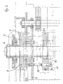
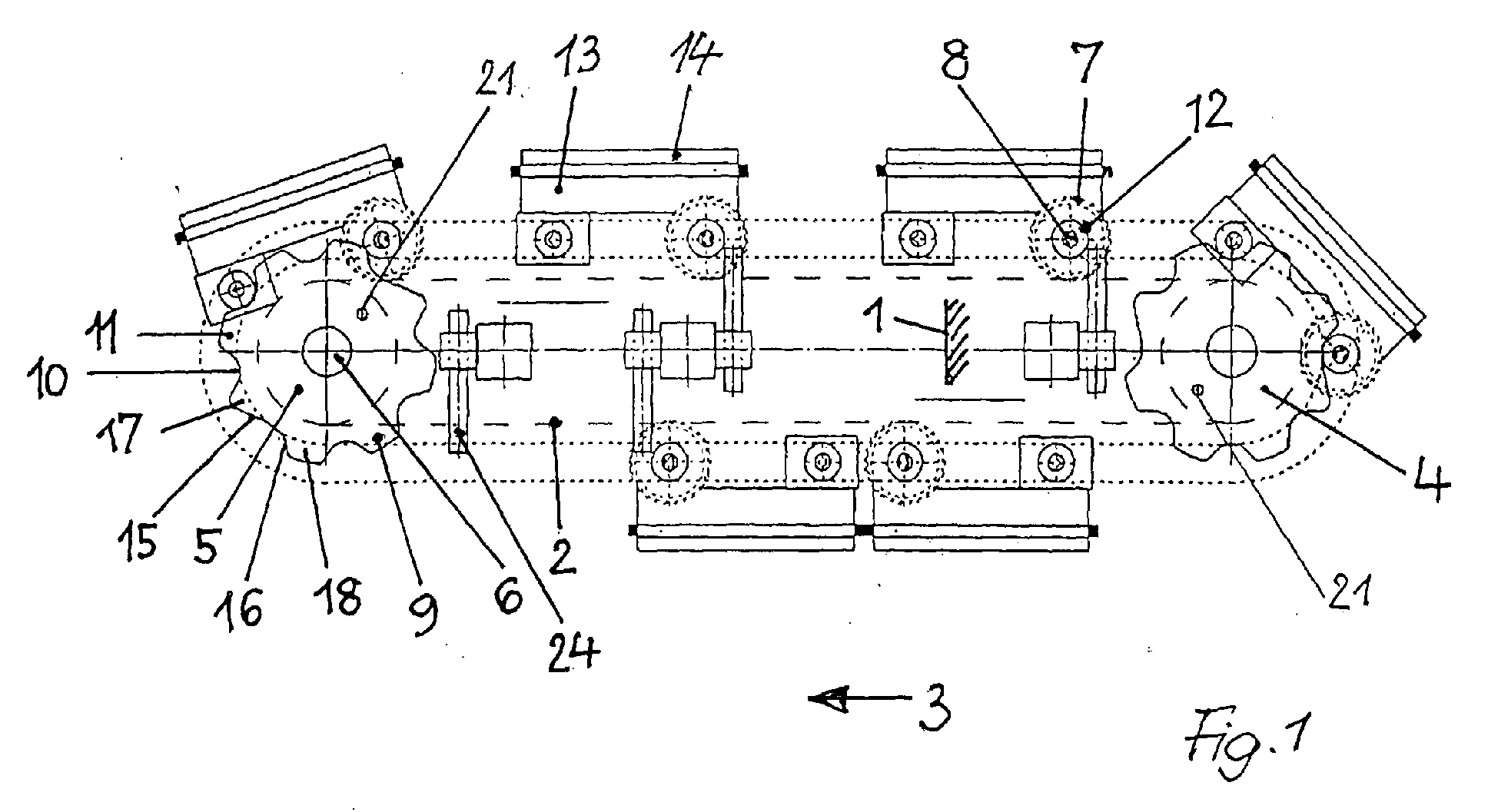
- Fig. 1 shows a formed in the form of a triplex chain conveyor chain 2, the in Running direction 3 via a chain deflection wheel 4 and a chain drive wheel 5 moves becomes.
- the drive shaft of the drive is designated 6.
- 8 Guide rollers 12 receives.
- On the drive shaft 6 of the chain drive wheel 5 is Coaxially a driving plate 9 with circumferentially formed teeth 11th arranged, the guide rollers 12 in a trough between two each Receive tooth flanks and thus arranged on the guide rollers 12 Transport workpiece carrier 13 with workpiece 14 on.
- the chain wheel 5 for the conveyor chain 2 sits on the drive shaft 6 rotatably with the driving plate 9, the one on the deflection shaft 6 via bearings 20th having rotatably arranged sensor disk 19 with associated sensor 21.
- the chain deflection wheel 4 is shown in FIG. 6 via a Clamping device 23 formed adjustable in the conveying direction of the chain conveyor.
- the tensioning device 23 shifts the chain deflection wheel and also causes a Clamping the conveyor chain when the conveyor chain due to the occurring during operation Wear a chain elongation and a larger center distance Retensioning required.
- On the circumference of the sensor disk 19 is free of slipping in a circumferential groove continuously arranged a rope 19a. That is a rope end of this rope firmly connected to the frame 1, the other end of the rope held resiliently.
- stopper 24 are designed as stops 25 and through Drive cylinder 26 are activated.
- the stoppers 24 are along fixed locations arranged the conveyor 2 and their drive cylinder 26 are over Initiators 27 controlled, the signals to the control and drive device for the Generate conveyor device 2 and a pinpoint stopping the tool carrier result.
- Photoelectric sensors 28 check whether the workpiece carrier is loaded.
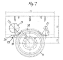
- the workpiece carrier with fixed on the axes of the output pinion 7 and arranged coaxially Toothed elements 29, which roll on their circular periphery 30, Pins, rotary elements or the like. 31, which in corresponding wells 32nd between each two adjacent teeth of the chain drive gear fifth intervention.
- a tooth arrangement is a separate Take-along disc dispensable and the driving of the toothing elements 29 in the Cogs of the sprocket runs with unchanged peripheral speed and with it smoothly.
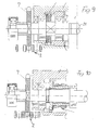
- FIG. 8 shows a section through the drive section of the conveyor device according to FIG Embodiment of Figures 6 and 7 represents.
- On a drive shaft 32 sits the chain drive wheel 33 for the conveyor chain 34.
- the conveyor chain 34 drives the chain sprocket 35, which is fixed on an axle 36, via a bearing 37, the axle 38 of the Workpiece carrier 39 and the braking device 40 receives, via an engagement element 41 the workpiece carrier 39 is applied.
- the brake device 40 is also executed in this embodiment as a multi-disc brake, the frictional engagement generated.
Landscapes
- Engineering & Computer Science (AREA)
- Mechanical Engineering (AREA)
- Control Of Conveyors (AREA)
- Devices For Conveying Motion By Means Of Endless Flexible Members (AREA)
- Belt Conveyors (AREA)
- Intermediate Stations On Conveyors (AREA)
- Specific Conveyance Elements (AREA)
- Vending Machines For Individual Products (AREA)
Abstract
Zum Fördern von industriellen Bauteilen sind auf einer umlaufenden
Förderbahn Bauteilträger (13) festgelegt, die im geradlinigen Verlauf
und im Umlenkbereich des Förderers vereinzelbar mit der Förderbahn
verbunden sind. Am Rahmengestell (1) der Fördervorrichtung sind
Stopperelemente (24) vorgesehen, die an definierten Stellen entlang der
Fördervorrichtung eine Vereinzelung der Bauteilträger auslösen. Das
Fördern der Bauteilträger erfolgt im geradlinigen Bereich der
Förderbahn über einen reibschlüssigen Antrieb (2) und das Fördern
der Bauteilträger im Umlenkbereich der Förderbahn über einen
formschlüssigen Antrieb (9).
Description
Die Erfindung betrifft eine Vorrichtung nach dem Oberbegriff des Anspruches 1.The invention relates to a device according to the preamble of
Fördervorrichtungen der gattungsgemäßen Art, die auch als Stauförderer bezeichnet werden, werden vor allem dort eingesetzt, wo Bauteile bzw. Werkstücke in einem Fertigungsprozess in eine Maschine, einen Roboter oder einen Arbeitsablauf allgemein eingeführt werden und die Bauteile angehalten bzw. gestaut werden müssen.Conveying devices of the generic type, also referred to as accumulation conveyor be used, especially where components or workpieces in one Manufacturing process into a machine, a robot or a workflow in general be introduced and the components must be stopped or stowed.
Die Bauteile werden von Bauteilträgern transportiert, die mit der Förderkettenanordnung kontinuierlich in Umlauf gesetzt werden. Die Bauteilträger werden an bestimmen Stellen des Umlaufes, insbesondere dort, wo der Förderer mit den Teilen beladen oder entladen wird, mit Hilfe von Vereinzelungsvorrichtungen, z.B. Stoppern, exakt gesteuert angehalten, um zu verhindern, dass die über den Transportförderer laufend angelieferten Bauteilträger mit den darauf festgelegten Bauteilen aneinander stoßen oder deren Abgabe behindern.The components are transported by component carriers which are connected to the conveyor chain arrangement be continuously circulated. The component carriers are on Determine points of circulation, especially where the conveyor with parts loaded or unloaded by means of singulating devices, e.g. stoppers, stopped precisely controlled to prevent the over the transport conveyor continuously supplied component carrier with the components fixed to each other encounter or impede their delivery.
Stauförderer weisen eine Rahmenkonstruktion mit Metall-, insbes. Alu-Profilen auf, die Führungen für die Rollenkettenanordnung besitzen, auf der die Bauteilträger aufgesetzt und mitgenommen werden. Mit einer Stopper- oder Vereinzelungsvorrichtung werden die auf einem Bauteilträger zu befördernden Bauteile an einer exakt festzulegenden Position, z.B. einer Belade- oder Entladestelle, z.B. mit Hilfe entsprechender Programmsteuerungen bereit gestellt und z.B. durch Roboter übernommen. Die Einheiten, die die Stopper- oder Vereinzelungsvorrichtungen aufnehmen, werden z.B. durch pneumatische Antriebszylinder in die jeweiligen Halte- oder Durchlaufpositionen der Bauteilträger gebracht und dort positioniert. Den Vereinzelungs- bzw. Stoppervorrichtungen sind Initiatoren zugeordnet, die feststellen, ob ein Bauteilträger an der entsprechenden Stoppervorrichtung vorhanden ist, ob ein Bauteilträger den Stopper verlassen hat, ob ein Bauteilträger nach dem Bestücken bzw. nach dem Entladen vorbei gelaufen ist, usw. Die von den Initiatoren generierten Signale melden der Stoppervorrichtung, ob der bestückte bzw. entladene Bauteilträger bereits weiter bewegt worden ist und damit Platz für den nachfolgenden Bauteilträger freigegeben hat. Um zu verhindern, dass ein Bauteilträger, der angehalten worden ist, wieder nach hinten geschoben werden kann, sind Anti-Rückkehrvorrichtungen vorgesehen. Lichtschranken oder entsprechende Sensoren werden eingesetzt, um festzustellen, ob ein Bauteil auf dem Bauteilträger vorhanden ist.Stauförderer have a frame construction with metal, esp. Alu-profiles, the Have guides for the roller chain assembly, mounted on the component carrier and be taken along. With a stopper or separating device the components to be transported on a component carrier at a precisely defined position Position, e.g. a loading or unloading point, e.g. with the help of appropriate Program controls provided and e.g. taken over by robots. The Units receiving the stopper or dicing devices are e.g. by pneumatic drive cylinder in the respective holding or Passed positions of the component carrier and positioned there. The Separation or stopper devices are assigned to initiators who determine whether a component carrier is present on the corresponding stopper device, whether a Component carrier has left the stopper, whether a component carrier after loading or after unloading has passed, etc. The generated by the initiators Signals signal the stopper device, whether the assembled or unloaded component carrier has already been moved further and thus space for the subsequent component carrier has released. To prevent a component carrier that has been stopped can be pushed backwards are anti-return devices intended. Photocells or corresponding sensors are used to determine if a component is present on the component carrier.
Während bei horizontalem Verlauf der Bauteilträger auf der umlaufenden Fördervorrichtung ein geringer Bedarf an Zugkraft besteht, da nur die Reibungsverluste zu kompensieren sind, ergibt sich bei der Umlenkung bzw. beim Übergang vom oberen zum unteren Trum der Fördervorichtung eine um ein Vielfaches höhere Beanspruchung, die durch die Veränderung der Schwerpunkthöhe und das dadurch entstehende höhere, auf die Fördervorrichtung einwirkende Moment bedingt ist, insbesondere, wenn die Werkstücke stehend transportiert werden.While with horizontal course of the component carrier on the circumferential Conveyor is a low demand for traction, since only the friction losses are to be compensated, arises during the deflection or at the transition from upper to the lower run of Fördervorichtung a many times higher Stress caused by the change in the center of gravity height and thereby resulting higher, acting on the conveyor torque is due in particular, when the workpieces are transported standing.
Aufgabe der Erfindung ist, die hohen Beanspruchungen an den Umlenkstellen des Förderers aus der Linear- in die Drehbewegung sicher und stoßfrei aufzunehmen und insbesondere das Einführen der Mitnehmer an den Werkstückträgern in die Mitnahmevorrichtung einwandfrei zu gestalten.The object of the invention is the high stresses at the deflection of the Conveyor from the linear to the rotational movement safely and bumpless record and in particular the insertion of the driver on the workpiece carriers in the Carrying device to make perfect.
Des weiteren ist Aufgabe der Erfindung, den reibschlüssigen und den formschlüssigen Antrieb so auszulegen, dass ein geringer Verschleiß, eine hohe Wartungsfreiheit und eine hohe Lebensdauer gewährleistet sind.Furthermore, object of the invention, the frictional and the positive locking Drive designed so that a low wear, a high maintenance and a long life are guaranteed.
Aufgabe der Erfindung ist ferner, den Übergang von Reibschluss auf Formschluss und den Einlauf der Führung für die Bauteilträger in die Mitnahmescheibe ruckfrei einzusteuern.The object of the invention is also the transition from frictional engagement to form fit and the inlet of the guide for the component carrier in the driving plate jerk-free einzusteuern.
Gemäß der Erfindung wird dies mit den Merkmalen des Kennzeichens des Anspruches
1 erreicht. Weitere Ausgestaltungen der Erfindung sind Gegenstand der
Unteransprüche. According to the invention, this is achieved with the features of the characterizing part of the
Der Reibschluss-Antrieb ist als Lamellenbremse ausgeführt, die auf der durchgehenden Antriebswelle mit Kettenrädern für die Bauteilträger angeordnet, in einem Gehäuse gekapselt und in Öl laufend ausgeführt ist. Daraus ergeben sich wesentliche Vorteile in Hinblick auf das Verhältnis von Gleit- zu Haftreibung, ein geringer Verschleiß, Wartungsfreiheit über die gesamte Lebensdauer und eine Reduzierung von durch Reibung erregten Schwingungen.The frictional drive is designed as a multi-disc brake, which on the continuous Drive shaft arranged with sprockets for the component carrier, in a housing encapsulated and running in oil running. This results in significant benefits with regard to the ratio of sliding to static friction, low wear, Maintenance-free over the entire life and a reduction of through Friction excited vibrations.
Durch den Formschluss-Antrieb in Form eines Mitnehmerrades nach der Erfindung im Bereich der Umlenkung der Förderkette ergibt sich eine besonders einfache, kostengünstige und robuste konstruktive Ausführung der Beförderung der Werkstückträger. Dabei ist ein zwangloser und stoßfreier Übergang der Rollenanordnung, die den Werkstückträger mit der Förderkette verbindet, in die dafür vorgesehenen Ausnehmungen, z.B. in Form von Zahnlücken zwischen jeweils zwei Zähnen der Mitnahmescheibe entscheidend, der dadurch erreicht wird, dass die Umfangsgeschwindigkeit der Kettenritzel einerseits und die Umfangsgeschwindigkeit der Mitnahmescheibe, die beide gleich groß sind oder in festem Verhältnis zueinander ausgelegt sind, ferner die Position der entsprechenden Ausnehmung der Mitnahmescheibe in Relation zur Entfernung der Rollenanordnung des Werkzeugträgers, und damit die Phasenlage beider festgestellt wird und eine Steuereinrichtung die jeweilige Rolle der Rollenanordnung der Ausnehmung der Mitnahmescheibe zuordnet, so dass die Rolle stoßfrei in die Lücke einlaufen kann.By the form-locking drive in the form of a Mitnehmerrades according to the invention in Area of deflection of the conveyor chain results in a particularly simple, inexpensive and robust structural design of the transport of the workpiece carrier. Here is an informal and shock-free transition of the roller assembly, the Workpiece carrier with the conveyor chain connects, in the recesses provided, e.g. in the form of tooth gaps between each two teeth of the driving disc crucial, which is achieved by the peripheral speed the sprocket on the one hand and the peripheral speed of the driving disc, the both are the same size or are designed in fixed relation to each other, also the Position of the corresponding recess of the driving disc in relation to Removal of the roller assembly of the tool carrier, and thus the phase position both is detected and a control device the respective role of Assigns roller arrangement of the recess of the driving plate, so that the role smoothly enter the gap.
Der Stopper ist im Prinzip ein Anschlag, der den Werkzeugträger oder die den Werkzeugträger aufnehmende Achse beaufschlagt. Die Betätigung des/der Stopper erfolgt vorzugsweise über Antriebszylinder, die mechanisch, pneumatisch, hydraulisch oder auch elektrisch arbeiten. Die Position des Zylinders wird z.B. über Initiatoren gesteuert, die Signale an die Steuereinrichtung geben, damit der Bauteilträger punktgenau angehalten wird.The stopper is in principle a stop, the tool carrier or the Tool carrier receiving axis acted upon. The operation of the stopper (s) is preferably via drive cylinder, the mechanical, pneumatic, hydraulic or work electrically. The position of the cylinder is e.g. about initiators controlled to give the signals to the controller, thus the component carrier is stopped precisely.
Stopper sind vorzugsweise an Stellen längs der Fördervorrichtung vorgesehen, an denen ein Bestücken und Entladen der Werkzeugträger erforderlich ist, um einen möglichen Stau oder eine Kollision zu verhindern bzw. der Werkstückträger an einer definierten Stelle zum Stehen kommt, damit der Roboter punktgenau das Werkstück zugreifen kann. Die Initiatoren prüfen hierbei, ob z.B. ein Wekstückträger den Beladestopper verlassen hat, bevor ein weiterer Werkstückträger zugeführt wird.Stoppers are preferably provided at locations along the conveyor to which a loading and unloading of the tool carrier is required to one possible jam or to prevent a collision or the workpiece carrier on a stop, so that the robot precisely the workpiece can access. The initiators check here, if e.g. a Wekstückträger the Beladestopper has left before another workpiece carrier is supplied.
Nachstehend wird anhand der Zeichnungen eine Ausführungsform der Erfindung dargestellt. Die Figuren zeigen:
- Fig. 1
- eine Gesamtprinzipdarstellung einer Ausführungsform der erfindungsgemäßen Fördervorrichtung mit Mitnahmescheiben und Werkstückträgern in Ansicht von der Seite,
- Fig. 2
- eine Prinzipansicht der erfindungsgemäßen Fördervorrichtung im Schnitt und in vergrößerter Teilansicht,
- Fig. 3
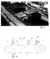
- eine Digitalbilddarstellung in perspektivischer Gesamtansicht,
- Fig. 4
- eine Digitalbilddarstellung von Mitnahmescheibe und Kettenrad mit Kette und Werkstückträger in perspektivischer Teilansicht,
- Fig. 5
- eine Prinzipdarstellung der erfindungsgemäßen Fördervorrichtung mit Stoppern und Initiatoren in Ansicht von der Seite,
- Fig. 6
- eine Prinzipdarstellung der erfindungsgemäßen Fördervorrichtung mit Spannvorrichtung,
- Fig. 7
- eine weitere Ausführungsform der Erfindung mit Abtriebsritzel, Verzahnungsvorrichtung und Kettenrad, in seitlicher Ansicht,
- Fig. 8
- eine Schnittdarstellung der erfindungsgemäßen Fördervorrichtung mit Verkettungsvorrichtung in Schnittdarstellung und vergrößerter Ansicht,
- Fig. 9
- eine Ausführungsform einer Lamellenbremse in Schnittansicht,
- Fig. 10
- eine Ausführungsform einer Klauenkupplung in Schnittansicht, und
- Fig. 11
- die Darstellung einer abgeänderten Ausführunsform einer Lamellenbremse in Verbindung mit Fördervorrichtung und Werkzeugträger.
- Fig. 1
- an overall principle view of an embodiment of the conveyor device according to the invention with driving discs and workpiece carriers in side view,
- Fig. 2
- a schematic view of the conveyor device according to the invention in section and in an enlarged partial view,
- Fig. 3
- a digital image representation in a perspective overall view,
- Fig. 4
- a digital image representation of driving plate and sprocket with chain and workpiece carrier in a perspective partial view,
- Fig. 5
- a schematic diagram of the conveyor device according to the invention with stoppers and initiators in side view,
- Fig. 6
- a schematic diagram of the conveyor device according to the invention with tensioning device,
- Fig. 7
- a further embodiment of the invention with output pinion, gear device and sprocket, in a side view,
- Fig. 8
- a sectional view of the conveyor device according to the invention with linking device in sectional view and enlarged view,
- Fig. 9
- an embodiment of a multi-disc brake in sectional view,
- Fig. 10
- an embodiment of a dog clutch in sectional view, and
- Fig. 11
- the representation of a modified Ausführunsform a multi-disc brake in conjunction with conveyor and tool carrier.
Fig. 1 zeigt eine in Form einer Triplexkette ausgebildete Förderkette 2, die in
Laufrichtung 3 über ein Ketten-Umlenkrad 4 und ein Ketten-Antriebsrad 5 bewegt
wird. Die Antriebswelle des Antriebs ist mit 6 bezeichnet. Durch die Förderkette 2
wird ein Abtriebsritzel 7 angetrieben, das auf einer gemeinsamen Achse 8
Führungsrollen 12 aufnimmt. Auf der Antriebswelle 6 des Kettenantriebsrades 5 ist
koaxial eine Mitnahmescheibe 9 mit in Umfangsrichtung ausgebildeten Zähnen 11
angeordnet, die die Führungsrollen 12 in einer Mulde zwischen jeweils zwei
Zahnflanken aufnehmen und damit den auf den Führungsrollen 12 angeordneten
Werkstückträger 13 mit Werkstück 14 weiter transportieren.Fig. 1 shows a formed in the form of a triplex
Beim Übergang des Werkstückträgers 13 aus der horizontalen Bewegung in die
teilkreisförmige Umlenkbewegung, d.h. beim Übergang von Reibschluss in Formschluss
tritt eine Differenzgeschwindigkeit aufgrund der geänderten Umfangsgeschwindigkeit
in der Bewegung der Führungsrollen auf, so dass ein gezieltes
Einsteuern der vorlaufenden Zahnflanke erforderlich ist, um ein ruckfreies Einführen
des Zahnes in die zugeordnete Mulde der Mitnahmescheibe zu erzielen. Dies wird
dadurch unterstützt, dass die vorlaufende Zahnflanke 15 flacher ausgebildet ist als die
nachlaufende Zahnflanke 16, die ihre normale Form beibehalten kann, so dass das
Einlaufen der Führungsrolle in die Zahnmulde ruckfrei und kontinuierlich erfolgt. Dies
ist schematisch in der Ausführung des Ketten-Antriebsrades 5 in Fig. 1 anhand von
zwei diametral gegenüberliegenden Zähnen 17, 18 des Antriebsrades 5 dargestellt, bei
denen die vorlaufende Zahnflanke 15 flacher bzw. weniger steil ausgeführt ist als die
nachlaufende Zahnflanke 16.During the transition of the
Auf der Antriebswelle 6 sitzt, wie Fig. 2 zeigt, das Kettenrad 5 für die Förderkette 2
drehfest mit der Mitnahmescheibe 9, die eine auf der Umlenkwelle 6 über Lager 20
drehbar angeordnete Sensorscheibe 19 mit zugeordnetem Sensor 21 aufweist. Der
Sensor 21 ist auf einen Markiergegenstand 22 auf der Mitnahmescheibe 9 ausgerichtet
und mißt die Winkelposition. Das Ketten-Umlenkrad 4 ist nach Fig. 6 über eine
Spannvorrichtung 23 in der Förderrichtung des Kettenförderers verstellbar ausgebildet.
Die Spannvorrichtung 23 verschiebt das Ketten-Umlenkrad und bewirkt ferner ein
Spannen der Förderkette, wenn die Förderkette aufgrund des im Betrieb auftretenden
Verschleißes eine Kettenlängung und einen größeren Achsabstand durch
Nachspannen erfordert. Auf dem Umfang der Sensorscheibe 19 ist gleitungsfrei in
einer Umfangsnut laufend ein Seil 19a angeordnet. Das eine Seilende dieses Seiles ist
mit dem Rahmengestell 1 fest verbunden, das andere Seilende federnd gegengehalten. As shown in FIG. 2, the
Bei Änderung des Abstandes zwischen der Achse des Umlenkrades 4 und dem letzten
Stopper vor dem Einlauf bewirkt der Werkstückträger in diese Umlenkung eine
entsprechende Verdrehung der Sensorscheibe 19. Bei Veränderung des Abstandes
zwischen Stopper und Umlenkung wird dabei durch Phasenverschiebung des die
Deaktivierung des Stoppers auslösenden Signals ein exakter Eintritt des
Werkstückträgers mit seinen Führungselementen in die Mitnahmescheibe 9 sicher
gestellt.When changing the distance between the axis of the
Wie in Fig. 5 dargestellt, sind an entsprechenden Stellen längs der Fördervorrichtung
2, an denen ein Bestücken, Entladen und Rücklaufen der Werkstückträger erforderlich
ist, Stopper 24 vorgesehen, die als Anschläge 25 ausgebildet sind und die durch
Antriebs-zylinder 26 aktiviert werden. Die Stopper 24 sind an festen Stellen entlang
der Fördervorrichtung 2 angeordnet und ihre Antriebszylinder 26 werden über
Initiatoren 27 gesteuert, die Signale an die Steuer- und Antriebsvorrichtung für die
Fördervorrich-tung 2 generieren und ein punktgenaues Stoppen der Werkzeugträger
ergeben. Lichtschranken 28 prüfen, ob der Werkstückträger beladen ist.As shown in Fig. 5, are at corresponding locations along the
Nach einer weiteren Ausführungsform der Erfindung nach Fig. 7 ist der Werkstückträger
mit auf den Achsen der Abtriebsritzel 7 fest und koaxial angeordneten
Verzahnungs-elementen 29 versehen, die auf ihrem kreisförmigen Umfang 30 Rollen,
Stifte, Drehelemente oder dergl. 31 aufweisen, welche in entsprechenden Mulden 32
zwischen jeweils zwei benachbarten Zähnen des Ketten-Antriebszahnrades 5
eingreifen. Mit einer derartigen Verzahnungsanordnung ist eine gesonderte
Mitnahmescheibe entbehrlich und das Einsteuern der Verzahnungselemente 29 in die
Zahnmulden des Kettenrades verläuft mit unveränderter Umfangsgeschwindigkeit und
damit ruckfrei.According to a further embodiment of the invention according to Fig. 7, the workpiece carrier
with fixed on the axes of the
Fig. 8 stellt einen Schnitt durch den Antriebsabschnitt der Fördervorrichtung nach der
Ausführungsform der Figuren 6 und 7 dar. Auf einer Antriebswelle 32 sitzt das Ketten-Antriebsrad
33 für die Förderkette 34. Die Förderkette 34 treibt das Kettenritzel 35 an,
das auf einer Achse 36 festgelegt ist, die über ein Lager 37 den Achsträger 38 des
Werkstückträgers 39 sowie die Bremsvorrichtung 40 aufnimmt, die über ein Eingriffselement
41 den Werkstückträger 39 beaufschlagt. Die Bremsvorrichtung 40 ist auch
bei dieser Ausführungsform als Lamellenbremse ausgeführt, die den Reibschluss
erzeugt. FIG. 8 shows a section through the drive section of the conveyor device according to FIG
Embodiment of Figures 6 and 7 represents. On a
- 11
- Rahmengestellframe
- 22
- Förderkette (Triplex-Kette)Conveyor chain (triplex chain)
- 33
- Laufrichtungdirection
- 44
- Ketten-UmlenkradChain guide wheel
- 55
- Ketten-AntriebsradChain drive
- 66
- Antriebswelledrive shaft
- 77
- Abtriebsritzeloutput pinion
- 88th
- Achseaxis
- 99
- Mitnahmescheibedriving plate
- 1010
- Aussparungenrecesses
- 1111
- Zähneteeth
- 1212
- Führungrollenguide rollers
- 1313
- WerkstückträgerWorkpiece carrier
- 1414
- Werkstückworkpiece
- 15, 1615, 16
- Zahnflankentooth flanks
- 17, 1817, 18
- Zähneteeth
- 1919
- Sensorscheibesensor disk
- 19a19a
- Seilrope
- 2020
- Lagercamp
- 2121
- Sensorsensor
- 2222
- MarkiergegenstandMarkiergegenstand
- 2323
- Spannvorrichtungjig
- 23a, 23b23a, 23b
- Spannfedertension spring
- 2424
- Stopperstopper
- 2525
- Anschlagattack
- 2626
- Antriebszylinderdrive cylinder
- 2727
- Initiatorinitiator
- 2828
- Lichtschrankephotocell
- 2929
- Verzahnungselement toothed element
- 3030
- Kreisumfangcircumference
- 3131
- Führungselemente, z.B.Rollen, StifteGuide elements, e.g. rollers, pins
- 3232
- Muldetrough
- 3333
- Ketten-AntriebsradChain drive
- 3434
- Förderketteconveyor chain
- 3535
- Kettenritzelsprocket
- 3636
- Achseaxis
- 3737
- Lagercamp
- 3838
- Achsträgeraxle
- 3939
- WerkstückträgerWorkpiece carrier
- 4040
- Bremsvorrichtungbraking device
- 4141
- Eingriffselementengaging member
Claims (16)
Applications Claiming Priority (2)
| Application Number | Priority Date | Filing Date | Title |
|---|---|---|---|
| DE10329156 | 2003-06-27 | ||
| DE10329156 | 2003-06-27 |
Publications (3)
| Publication Number | Publication Date |
|---|---|
| EP1559664A2 true EP1559664A2 (en) | 2005-08-03 |
| EP1559664A3 EP1559664A3 (en) | 2005-12-14 |
| EP1559664B1 EP1559664B1 (en) | 2007-06-20 |
Family
ID=33546699
Family Applications (1)
| Application Number | Title | Priority Date | Filing Date |
|---|---|---|---|
| EP04015059A Expired - Lifetime EP1559664B1 (en) | 2003-06-27 | 2004-06-26 | Device for conveying articles |
Country Status (3)
| Country | Link |
|---|---|
| EP (1) | EP1559664B1 (en) |
| AT (1) | ATE365139T1 (en) |
| DE (2) | DE102004030958B4 (en) |
Cited By (4)
| Publication number | Priority date | Publication date | Assignee | Title |
|---|---|---|---|---|
| CN110498205A (en) * | 2019-08-09 | 2019-11-26 | 广东三和管桩股份有限公司 | A kind of tubular pole carrier chain and control system, method, electronic equipment, storage medium |
| CN112278633A (en) * | 2020-10-28 | 2021-01-29 | 宁波伟隆港口机械有限公司 | Automatic disassembling and assembling system for container lockset |
| CN113135036A (en) * | 2020-01-20 | 2021-07-20 | 海德堡印刷机械股份公司 | Equipment for manipulating printing plates on a printing press |
| CN115771717A (en) * | 2023-02-10 | 2023-03-10 | 广东众智智能装备股份有限公司 | Laminated cell tray circulation system for lithium battery production |
Families Citing this family (7)
| Publication number | Priority date | Publication date | Assignee | Title |
|---|---|---|---|---|
| CN101475086B (en) * | 2009-01-09 | 2010-12-29 | 广东三和管桩有限公司 | Pipe die conveyor in pipe pile production process |
| DE102009056545B4 (en) * | 2009-12-03 | 2017-05-04 | ALTRATEC Automation GmbH | Closed circulation conveyor with a drive chain |
| GB201020067D0 (en) * | 2010-11-26 | 2011-01-12 | Meadwestvaco Packaging Systems | Apparatus, methods of operation of same and tools for use with apparatus |
| DE202011108545U1 (en) * | 2011-12-01 | 2012-01-17 | Tünkers Iberica S.L. | Accumulation conveyor |
| DE102016103211B4 (en) | 2016-02-24 | 2017-10-19 | Markus Koppold | Separation device and method for separating |
| CN112374019B (en) * | 2020-11-11 | 2022-01-14 | 湖南省辰波建设有限公司 | Intelligent wear-resistant quality-guaranteeing sandstone aggregate closed conveying chute device |
| DE102024000600B3 (en) * | 2024-02-24 | 2025-03-06 | Olaf und André Tünkers GbR (vertretungsberechtigter Gesellschafter:Dipl.-Ing. Olaf Tünkers, 40883 Ratingen) | Vertical pallet storage designed as an accumulation conveyor, especially for use in the body construction of the automotive industry |
Family Cites Families (16)
| Publication number | Priority date | Publication date | Assignee | Title |
|---|---|---|---|---|
| US3057456A (en) * | 1959-08-04 | 1962-10-09 | Sig Schweiz Industrieges | Endless type conveyer |
| USRE25886E (en) * | 1961-02-27 | 1965-10-26 | Manufacturing system using free floating fixture line | |
| BE639931A (en) * | 1963-01-14 | |||
| GB1042168A (en) * | 1963-01-14 | 1966-09-14 | Don Ashton Cargill | Improvements in or relating to conveyor systems |
| DE2712214A1 (en) * | 1977-03-19 | 1978-09-28 | Automation Klaus Th Kraemer Kg | Pallet transporter with circulating conveyor chain - has upright attached pallets moved to loading station and suspended ones moved away |
| DE3033373A1 (en) * | 1980-09-04 | 1982-05-19 | Carl Hurth Maschinen- und Zahnradfabrik GmbH & Co, 8000 München | PALLET MAGAZINE |
| DE3124898C2 (en) * | 1981-06-25 | 1986-04-10 | KBH Produktions-Automation GmbH & Co KG, 5628 Heiligenhaus | Device for transferring and redirecting pallets |
| DE3629372C2 (en) * | 1986-08-29 | 1993-10-21 | Gsa Ges Fuer Sondermaschinen U | Pallet transport device |
| FR2630092B1 (en) * | 1988-04-14 | 1993-03-26 | Sgie Ind Sa | SHUTTLE COMPRISING A BRAKING DEVICE, ASSOCIATED WITH A SLOPE CONVEYOR FOR THE ACCUMULATION OF SHUTTLES |
| US4934515A (en) * | 1988-08-16 | 1990-06-19 | Litton Industrial Automation Systems, Inc. | Endless accumulating conveyor |
| DE3836952C2 (en) * | 1988-10-29 | 1995-04-27 | Matthias Malatitsch | Pallet conveyors |
| US5495933A (en) * | 1993-04-21 | 1996-03-05 | Roberts Sinto Corporation | Chain driven pallet accumulating over/under chain conveyor |
| DE9416115U1 (en) * | 1994-10-06 | 1995-08-03 | F+S Automationstechnik GmbH, 74229 Oedheim | Pallet accumulation conveyor |
| US5735384A (en) * | 1996-08-29 | 1998-04-07 | Western Atlas, Inc. | Endless accumulating conveyor |
| DE19739431A1 (en) * | 1997-09-09 | 1999-03-11 | Altratec Montagesysteme | Pallet conveyer system for assembly line operations |
| US6415906B2 (en) * | 2000-04-04 | 2002-07-09 | Inno-Veyor, Inc. | Method and apparatus for transferring pallets around an end terminal in a conveyor assembly |
-
2004
- 2004-06-26 AT AT04015059T patent/ATE365139T1/en not_active IP Right Cessation
- 2004-06-26 DE DE102004030958A patent/DE102004030958B4/en not_active Expired - Fee Related
- 2004-06-26 EP EP04015059A patent/EP1559664B1/en not_active Expired - Lifetime
- 2004-06-26 DE DE502004004131T patent/DE502004004131D1/en not_active Expired - Lifetime
Cited By (6)
| Publication number | Priority date | Publication date | Assignee | Title |
|---|---|---|---|---|
| CN110498205A (en) * | 2019-08-09 | 2019-11-26 | 广东三和管桩股份有限公司 | A kind of tubular pole carrier chain and control system, method, electronic equipment, storage medium |
| CN113135036A (en) * | 2020-01-20 | 2021-07-20 | 海德堡印刷机械股份公司 | Equipment for manipulating printing plates on a printing press |
| CN112278633A (en) * | 2020-10-28 | 2021-01-29 | 宁波伟隆港口机械有限公司 | Automatic disassembling and assembling system for container lockset |
| CN112278633B (en) * | 2020-10-28 | 2022-07-26 | 宁波伟隆港口机械有限公司 | Automatic disassembling and assembling system for container lockset |
| CN115771717A (en) * | 2023-02-10 | 2023-03-10 | 广东众智智能装备股份有限公司 | Laminated cell tray circulation system for lithium battery production |
| CN115771717B (en) * | 2023-02-10 | 2023-03-31 | 广东众智智能装备股份有限公司 | Laminated cell tray circulation system for lithium battery production |
Also Published As
| Publication number | Publication date |
|---|---|
| DE502004004131D1 (en) | 2007-08-02 |
| DE102004030958A1 (en) | 2005-01-27 |
| EP1559664B1 (en) | 2007-06-20 |
| DE102004030958B4 (en) | 2007-09-20 |
| ATE365139T1 (en) | 2007-07-15 |
| EP1559664A3 (en) | 2005-12-14 |
Similar Documents
| Publication | Publication Date | Title |
|---|---|---|
| AT393819B (en) | CONVEYOR FOR WORKPIECES OR WORKPIECE CARRIER, ESPECIALLY FOR AN ASSEMBLY MACHINE | |
| EP2565148B1 (en) | Stacker crane with a lifting carriage powered by a kind of pulley block | |
| EP3571145B1 (en) | Drive device, drive element, and conveyor wagon drive | |
| WO2003106305A1 (en) | Roller arrangement for an accumulating roller conveyor | |
| EP1559664A2 (en) | Device for conveying articles | |
| DE102010028055A1 (en) | Transport device with improved runnability | |
| DE3940470C2 (en) | ||
| EP1133438B1 (en) | Belt conveyor | |
| EP3225571A1 (en) | Conveying device for conveying hanging items | |
| DE3128824A1 (en) | ELECTRIC RAILWAY | |
| EP3573918B1 (en) | Continuous cable winch | |
| WO1993006029A1 (en) | Drive and guide device for continuous handling equipment | |
| EP3529180A1 (en) | Conveying system | |
| EP0377884B1 (en) | Method and device for transporting goods | |
| EP3642140A1 (en) | Transport device comprising carriages guided such that they can move on a rail | |
| EP0636559B1 (en) | Curved belt conveyor | |
| EP1102718A1 (en) | Method and device for guiding a chain in the region of chain-wheels of a continuous transport unit | |
| DE2813063C2 (en) | ||
| EP1473257A2 (en) | Device and system for conveying articles on two adjacent roller conveyors | |
| DE10051758B4 (en) | Positioning device and its working method | |
| DE2924260A1 (en) | CONVEYOR ROLE | |
| DE68902402T2 (en) | COMBINATION OF DRIVE DEVICE AND FLEXIBLE CONVEYOR ELEMENT. | |
| CH372976A (en) | Conveyor device on a processing machine | |
| DE20022495U1 (en) | Positioning device | |
| DE202004007435U1 (en) | An accumulation roller conveyor has a number of electric motor driven drive rollers with intermediate friction drive rollers to transport pallets and allow a static build-up if necessary |
Legal Events
| Date | Code | Title | Description |
|---|---|---|---|
| PUAI | Public reference made under article 153(3) epc to a published international application that has entered the european phase |
Free format text: ORIGINAL CODE: 0009012 |
|
| AK | Designated contracting states |
Kind code of ref document: A2 Designated state(s): AT BE BG CH CY CZ DE DK EE ES FI FR GB GR HU IE IT LI LU MC NL PL PT RO SE SI SK TR |
|
| AX | Request for extension of the european patent |
Extension state: AL HR LT LV MK |
|
| PUAL | Search report despatched |
Free format text: ORIGINAL CODE: 0009013 |
|
| AK | Designated contracting states |
Kind code of ref document: A3 Designated state(s): AT BE BG CH CY CZ DE DK EE ES FI FR GB GR HU IE IT LI LU MC NL PL PT RO SE SI SK TR |
|
| AX | Request for extension of the european patent |
Extension state: AL HR LT LV MK |
|
| 17P | Request for examination filed |
Effective date: 20060516 |
|
| 17Q | First examination report despatched |
Effective date: 20060707 |
|
| AKX | Designation fees paid |
Designated state(s): AT BE BG CH CY CZ DE DK EE ES FI FR GB GR HU IE IT LI LU MC NL PL PT RO SE SI SK TR |
|
| GRAP | Despatch of communication of intention to grant a patent |
Free format text: ORIGINAL CODE: EPIDOSNIGR1 |
|
| GRAS | Grant fee paid |
Free format text: ORIGINAL CODE: EPIDOSNIGR3 |
|
| GRAA | (expected) grant |
Free format text: ORIGINAL CODE: 0009210 |
|
| AK | Designated contracting states |
Kind code of ref document: B1 Designated state(s): AT BE BG CH CY CZ DE DK EE ES FI FR GB GR HU IE IT LI LU MC NL PL PT RO SE SI SK TR |
|
| REG | Reference to a national code |
Ref country code: GB Ref legal event code: FG4D Free format text: NOT ENGLISH |
|
| REG | Reference to a national code |
Ref country code: CH Ref legal event code: EP |
|
| REG | Reference to a national code |
Ref country code: IE Ref legal event code: FG4D Free format text: LANGUAGE OF EP DOCUMENT: GERMAN |
|
| REF | Corresponds to: |
Ref document number: 502004004131 Country of ref document: DE Date of ref document: 20070802 Kind code of ref document: P |
|
| PG25 | Lapsed in a contracting state [announced via postgrant information from national office to epo] |
Ref country code: SE Free format text: LAPSE BECAUSE OF FAILURE TO SUBMIT A TRANSLATION OF THE DESCRIPTION OR TO PAY THE FEE WITHIN THE PRESCRIBED TIME-LIMIT Effective date: 20070920 |
|
| PG25 | Lapsed in a contracting state [announced via postgrant information from national office to epo] |
Ref country code: PL Free format text: LAPSE BECAUSE OF FAILURE TO SUBMIT A TRANSLATION OF THE DESCRIPTION OR TO PAY THE FEE WITHIN THE PRESCRIBED TIME-LIMIT Effective date: 20070620 |
|
| NLV1 | Nl: lapsed or annulled due to failure to fulfill the requirements of art. 29p and 29m of the patents act | ||
| BERE | Be: lapsed |
Owner name: WOLF VERWALTUNGS G.M.B.H. & CO. KG Effective date: 20070630 |
|
| GBV | Gb: ep patent (uk) treated as always having been void in accordance with gb section 77(7)/1977 [no translation filed] |
Effective date: 20070620 |
|
| REG | Reference to a national code |
Ref country code: IE Ref legal event code: FD4D |
|
| PG25 | Lapsed in a contracting state [announced via postgrant information from national office to epo] |
Ref country code: NL Free format text: LAPSE BECAUSE OF FAILURE TO SUBMIT A TRANSLATION OF THE DESCRIPTION OR TO PAY THE FEE WITHIN THE PRESCRIBED TIME-LIMIT Effective date: 20070620 Ref country code: BG Free format text: LAPSE BECAUSE OF FAILURE TO SUBMIT A TRANSLATION OF THE DESCRIPTION OR TO PAY THE FEE WITHIN THE PRESCRIBED TIME-LIMIT Effective date: 20070920 Ref country code: ES Free format text: LAPSE BECAUSE OF FAILURE TO SUBMIT A TRANSLATION OF THE DESCRIPTION OR TO PAY THE FEE WITHIN THE PRESCRIBED TIME-LIMIT Effective date: 20071001 Ref country code: SI Free format text: LAPSE BECAUSE OF FAILURE TO SUBMIT A TRANSLATION OF THE DESCRIPTION OR TO PAY THE FEE WITHIN THE PRESCRIBED TIME-LIMIT Effective date: 20070620 Ref country code: PT Free format text: LAPSE BECAUSE OF FAILURE TO SUBMIT A TRANSLATION OF THE DESCRIPTION OR TO PAY THE FEE WITHIN THE PRESCRIBED TIME-LIMIT Effective date: 20071120 Ref country code: MC Free format text: LAPSE BECAUSE OF NON-PAYMENT OF DUE FEES Effective date: 20070630 Ref country code: IE Free format text: LAPSE BECAUSE OF FAILURE TO SUBMIT A TRANSLATION OF THE DESCRIPTION OR TO PAY THE FEE WITHIN THE PRESCRIBED TIME-LIMIT Effective date: 20070620 Ref country code: CZ Free format text: LAPSE BECAUSE OF FAILURE TO SUBMIT A TRANSLATION OF THE DESCRIPTION OR TO PAY THE FEE WITHIN THE PRESCRIBED TIME-LIMIT Effective date: 20070620 |
|
| EN | Fr: translation not filed | ||
| PG25 | Lapsed in a contracting state [announced via postgrant information from national office to epo] |
Ref country code: SK Free format text: LAPSE BECAUSE OF FAILURE TO SUBMIT A TRANSLATION OF THE DESCRIPTION OR TO PAY THE FEE WITHIN THE PRESCRIBED TIME-LIMIT Effective date: 20070620 |
|
| PG25 | Lapsed in a contracting state [announced via postgrant information from national office to epo] |
Ref country code: BE Free format text: LAPSE BECAUSE OF NON-PAYMENT OF DUE FEES Effective date: 20070630 |
|
| PLBE | No opposition filed within time limit |
Free format text: ORIGINAL CODE: 0009261 |
|
| STAA | Information on the status of an ep patent application or granted ep patent |
Free format text: STATUS: NO OPPOSITION FILED WITHIN TIME LIMIT |
|
| PG25 | Lapsed in a contracting state [announced via postgrant information from national office to epo] |
Ref country code: IT Free format text: LAPSE BECAUSE OF FAILURE TO SUBMIT A TRANSLATION OF THE DESCRIPTION OR TO PAY THE FEE WITHIN THE PRESCRIBED TIME-LIMIT Effective date: 20070620 Ref country code: DK Free format text: LAPSE BECAUSE OF FAILURE TO SUBMIT A TRANSLATION OF THE DESCRIPTION OR TO PAY THE FEE WITHIN THE PRESCRIBED TIME-LIMIT Effective date: 20070620 Ref country code: GR Free format text: LAPSE BECAUSE OF FAILURE TO SUBMIT A TRANSLATION OF THE DESCRIPTION OR TO PAY THE FEE WITHIN THE PRESCRIBED TIME-LIMIT Effective date: 20070921 Ref country code: GB Free format text: LAPSE BECAUSE OF FAILURE TO SUBMIT A TRANSLATION OF THE DESCRIPTION OR TO PAY THE FEE WITHIN THE PRESCRIBED TIME-LIMIT Effective date: 20070620 |
|
| 26N | No opposition filed |
Effective date: 20080325 |
|
| PG25 | Lapsed in a contracting state [announced via postgrant information from national office to epo] |
Ref country code: RO Free format text: LAPSE BECAUSE OF FAILURE TO SUBMIT A TRANSLATION OF THE DESCRIPTION OR TO PAY THE FEE WITHIN THE PRESCRIBED TIME-LIMIT Effective date: 20070620 |
|
| PG25 | Lapsed in a contracting state [announced via postgrant information from national office to epo] |
Ref country code: FR Free format text: LAPSE BECAUSE OF FAILURE TO SUBMIT A TRANSLATION OF THE DESCRIPTION OR TO PAY THE FEE WITHIN THE PRESCRIBED TIME-LIMIT Effective date: 20080222 |
|
| PG25 | Lapsed in a contracting state [announced via postgrant information from national office to epo] |
Ref country code: AT Free format text: LAPSE BECAUSE OF NON-PAYMENT OF DUE FEES Effective date: 20070626 |
|
| PG25 | Lapsed in a contracting state [announced via postgrant information from national office to epo] |
Ref country code: EE Free format text: LAPSE BECAUSE OF FAILURE TO SUBMIT A TRANSLATION OF THE DESCRIPTION OR TO PAY THE FEE WITHIN THE PRESCRIBED TIME-LIMIT Effective date: 20070620 |
|
| REG | Reference to a national code |
Ref country code: CH Ref legal event code: PL |
|
| PG25 | Lapsed in a contracting state [announced via postgrant information from national office to epo] |
Ref country code: FI Free format text: LAPSE BECAUSE OF FAILURE TO SUBMIT A TRANSLATION OF THE DESCRIPTION OR TO PAY THE FEE WITHIN THE PRESCRIBED TIME-LIMIT Effective date: 20070620 |
|
| PG25 | Lapsed in a contracting state [announced via postgrant information from national office to epo] |
Ref country code: CH Free format text: LAPSE BECAUSE OF NON-PAYMENT OF DUE FEES Effective date: 20080630 Ref country code: LI Free format text: LAPSE BECAUSE OF NON-PAYMENT OF DUE FEES Effective date: 20080630 |
|
| PG25 | Lapsed in a contracting state [announced via postgrant information from national office to epo] |
Ref country code: CY Free format text: LAPSE BECAUSE OF FAILURE TO SUBMIT A TRANSLATION OF THE DESCRIPTION OR TO PAY THE FEE WITHIN THE PRESCRIBED TIME-LIMIT Effective date: 20070620 |
|
| PG25 | Lapsed in a contracting state [announced via postgrant information from national office to epo] |
Ref country code: LU Free format text: LAPSE BECAUSE OF NON-PAYMENT OF DUE FEES Effective date: 20070626 |
|
| PG25 | Lapsed in a contracting state [announced via postgrant information from national office to epo] |
Ref country code: TR Free format text: LAPSE BECAUSE OF FAILURE TO SUBMIT A TRANSLATION OF THE DESCRIPTION OR TO PAY THE FEE WITHIN THE PRESCRIBED TIME-LIMIT Effective date: 20070620 Ref country code: HU Free format text: LAPSE BECAUSE OF FAILURE TO SUBMIT A TRANSLATION OF THE DESCRIPTION OR TO PAY THE FEE WITHIN THE PRESCRIBED TIME-LIMIT Effective date: 20071221 |
|
| REG | Reference to a national code |
Ref country code: DE Ref legal event code: R082 Ref document number: 502004004131 Country of ref document: DE Representative=s name: PATENTANWALTSKANZLEI MEYER, DE |
|
| REG | Reference to a national code |
Ref country code: DE Ref legal event code: R081 Ref document number: 502004004131 Country of ref document: DE Owner name: KTEC GMBH, DE Free format text: FORMER OWNER: WOLF VERWALTUNGS GMBH & CO. KG, 85290 GEISENFELD, DE Effective date: 20120725 Ref country code: DE Ref legal event code: R082 Ref document number: 502004004131 Country of ref document: DE Representative=s name: PATENTANWALTSKANZLEI MEYER, DE Effective date: 20120725 |
|
| REG | Reference to a national code |
Ref country code: DE Ref legal event code: R082 Ref document number: 502004004131 Country of ref document: DE Representative=s name: PATENTANWALTSKANZLEI MEYER, DE |
|
| REG | Reference to a national code |
Ref country code: DE Ref legal event code: R082 Ref document number: 502004004131 Country of ref document: DE Representative=s name: PATENTANWALTSKANZLEI MEYER, DE Effective date: 20130115 Ref country code: DE Ref legal event code: R081 Ref document number: 502004004131 Country of ref document: DE Owner name: KTEC GMBH, DE Free format text: FORMER OWNER: KTEC GMBH & CO. KG, 85290 GEISENFELD, DE Effective date: 20130115 |
|
| PGFP | Annual fee paid to national office [announced via postgrant information from national office to epo] |
Ref country code: DE Payment date: 20170428 Year of fee payment: 14 |
|
| REG | Reference to a national code |
Ref country code: DE Ref legal event code: R119 Ref document number: 502004004131 Country of ref document: DE |
|
| PG25 | Lapsed in a contracting state [announced via postgrant information from national office to epo] |
Ref country code: DE Free format text: LAPSE BECAUSE OF NON-PAYMENT OF DUE FEES Effective date: 20190101 |
|
| P01 | Opt-out of the competence of the unified patent court (upc) registered |
Effective date: 20230523 |