EP1559642A1 - Method of assembling motor vehicle body - Google Patents
Method of assembling motor vehicle body Download PDFInfo
- Publication number
- EP1559642A1 EP1559642A1 EP03754174A EP03754174A EP1559642A1 EP 1559642 A1 EP1559642 A1 EP 1559642A1 EP 03754174 A EP03754174 A EP 03754174A EP 03754174 A EP03754174 A EP 03754174A EP 1559642 A1 EP1559642 A1 EP 1559642A1
- Authority
- EP
- European Patent Office
- Prior art keywords
- joisted
- locating
- fixed
- car body
- movable rail
- Prior art date
- Legal status (The legal status is an assumption and is not a legal conclusion. Google has not performed a legal analysis and makes no representation as to the accuracy of the status listed.)
- Granted
Links
Images


Classifications
-
- B—PERFORMING OPERATIONS; TRANSPORTING
- B62—LAND VEHICLES FOR TRAVELLING OTHERWISE THAN ON RAILS
- B62D—MOTOR VEHICLES; TRAILERS
- B62D65/00—Designing, manufacturing, e.g. assembling, facilitating disassembly, or structurally modifying motor vehicles or trailers, not otherwise provided for
-
- B—PERFORMING OPERATIONS; TRANSPORTING
- B62—LAND VEHICLES FOR TRAVELLING OTHERWISE THAN ON RAILS
- B62D—MOTOR VEHICLES; TRAILERS
- B62D65/00—Designing, manufacturing, e.g. assembling, facilitating disassembly, or structurally modifying motor vehicles or trailers, not otherwise provided for
- B62D65/02—Joining sub-units or components to, or positioning sub-units or components with respect to, body shell or other sub-units or components
- B62D65/18—Transportation, conveyor or haulage systems specially adapted for motor vehicle or trailer assembly lines
-
- Y—GENERAL TAGGING OF NEW TECHNOLOGICAL DEVELOPMENTS; GENERAL TAGGING OF CROSS-SECTIONAL TECHNOLOGIES SPANNING OVER SEVERAL SECTIONS OF THE IPC; TECHNICAL SUBJECTS COVERED BY FORMER USPC CROSS-REFERENCE ART COLLECTIONS [XRACs] AND DIGESTS
- Y10—TECHNICAL SUBJECTS COVERED BY FORMER USPC
- Y10T—TECHNICAL SUBJECTS COVERED BY FORMER US CLASSIFICATION
- Y10T29/00—Metal working
- Y10T29/49—Method of mechanical manufacture
- Y10T29/49826—Assembling or joining
- Y10T29/49828—Progressively advancing of work assembly station or assembled portion of work
- Y10T29/49829—Advancing work to successive stations [i.e., assembly line]
-
- Y—GENERAL TAGGING OF NEW TECHNOLOGICAL DEVELOPMENTS; GENERAL TAGGING OF CROSS-SECTIONAL TECHNOLOGIES SPANNING OVER SEVERAL SECTIONS OF THE IPC; TECHNICAL SUBJECTS COVERED BY FORMER USPC CROSS-REFERENCE ART COLLECTIONS [XRACs] AND DIGESTS
- Y10—TECHNICAL SUBJECTS COVERED BY FORMER USPC
- Y10T—TECHNICAL SUBJECTS COVERED BY FORMER US CLASSIFICATION
- Y10T29/00—Metal working
- Y10T29/49—Method of mechanical manufacture
- Y10T29/49826—Assembling or joining
- Y10T29/49828—Progressively advancing of work assembly station or assembled portion of work
- Y10T29/49831—Advancing station
-
- Y—GENERAL TAGGING OF NEW TECHNOLOGICAL DEVELOPMENTS; GENERAL TAGGING OF CROSS-SECTIONAL TECHNOLOGIES SPANNING OVER SEVERAL SECTIONS OF THE IPC; TECHNICAL SUBJECTS COVERED BY FORMER USPC CROSS-REFERENCE ART COLLECTIONS [XRACs] AND DIGESTS
- Y10—TECHNICAL SUBJECTS COVERED BY FORMER USPC
- Y10T—TECHNICAL SUBJECTS COVERED BY FORMER US CLASSIFICATION
- Y10T29/00—Metal working
- Y10T29/49—Method of mechanical manufacture
- Y10T29/49826—Assembling or joining
- Y10T29/49895—Associating parts by use of aligning means [e.g., use of a drift pin or a "fixture"]
-
- Y—GENERAL TAGGING OF NEW TECHNOLOGICAL DEVELOPMENTS; GENERAL TAGGING OF CROSS-SECTIONAL TECHNOLOGIES SPANNING OVER SEVERAL SECTIONS OF THE IPC; TECHNICAL SUBJECTS COVERED BY FORMER USPC CROSS-REFERENCE ART COLLECTIONS [XRACs] AND DIGESTS
- Y10—TECHNICAL SUBJECTS COVERED BY FORMER USPC
- Y10T—TECHNICAL SUBJECTS COVERED BY FORMER US CLASSIFICATION
- Y10T29/00—Metal working
- Y10T29/53—Means to assemble or disassemble
- Y10T29/53961—Means to assemble or disassemble with work-holder for assembly
Definitions
- the present invention relates to a method of assembling a motor vehicle body. Specifically, the present invention relates to a method for pre-fixing bridging parts, such as a roof panel, a header inner and a frame back, to the left and right side members, which are welded to an underbody of a car.
- a car body includes main parts such as an underbody, left and right side members, and a roof panel.
- main parts such as an underbody, left and right side members, and a roof panel.
- the parts to be assembled are positioned relative to each other, using locating jigs, etc.
- the parts are fixed by spot welding, thereafter re-spot welded to be fixed completely.
- a conventional method of assembling a car body utilizes a significantly large locating jig for locating the main parts.
- a jig used to position the roof panel is larger than the roof panel itself.
- Such locating jig is installed above the car body assembly line and is movable up and down.
- the roof panel is transferred to a position below the locating jig, and set into the locating jig.
- the locating jig is lowered to position both edges of the roof panel on the upper ends of the side members. Finally, in this manner, the roof panel is spot welded to the side member.
- a motor for lifting the jig should bear a large load due to the large and heavy locating jig.
- a movable portion of the motor may suffer trouble such as wear, so that constant maintenance is needed for working the motor properly.
- the present invention has been proposed under the above-described circumstances. It is therefore an object of the present invention to realize reduction in size and weight of the locating jig used for a bridging part such as a roof panel, a header board and a frame back.
- the present invention provides a method of assembling a car body by spot welding a bridging part to a pair of side members fixed to an underbody of a car.
- the method comprising the steps of: placing a pair of frames at sides of a transfer line for transferring the underbody and the side members; attaching a plurality of detachable Seasted-locating jigs to the frame for locating the side member and the bridging part; and spot welding the side members to the bridging part, with the side members and the bridging part being clamped by the joisted-locating jigs.
- An appropriate transfer system is employed to convey the joisted-locating jig from the frame to a first stock area and to convey another joisted-locating jig from a second stock area to the frame for performing a joisted-locating jig change.
- the joisted-locating jig can be made lighter and smaller than conventional locating jig for roof panel. Thus, initial facility investment may be reduced. Further, the joisted-locating jig according to the present invention does not obstruct the assembly operation even if it is stored near the transfer line.
- the frame and the joisted-locating jig are positioned by a clamp mechanism.
- the transfer system includes a motor, a movable rail moved up and down by the motor, a fixed rail to be combined with the movable rail, and a pulley movable along the movable rail and the fixed rail.
- the joisted-locating jig is hung from the pulley.
- a sway prevention mechanism is provided for preventing the movable rail from swaying when the movable rail is apart from the fixed rail.
- the sway prevention mechanism includes a pair of vertical rods attached to the movable rail and a pair of fixed guides fixed to immovable structure.
- the vertical rod moves relative to the fixed guide be means of a roller.
- the movable rail is equipped with a fall-out prevention device, which is to prevent the pulley from falling out of the movable rail.
- the fall-out prevention device includes a stopper that turns on the pivot previously determined.
- the stopper is displaceable in the span between engaging and disengaging points of the stopper and the pulley.
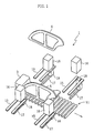
- Fig. 1 is a schematic view illustrating a side member spot welding station 1.
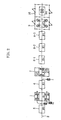
- the side member spot welding station 1 is installed at a predetermined place in a car body assembly line 2 (see Fig. 2).
- the car body assembly line 2 includes an underbody loading station (not shown) installed upstream of the side member spot welding station 1 (the left side in Fig. 2).
- an underbody 3 is set on coasters 13a, 13b (see Fig. 3).
- the underbody 3 including a rear portion facing downstream of the car body assembly line 2 for example, is carried by a roller conveyor 11 (see Fig. 4), to be sent to an underbody setting station 5 (#0) and to the side member spot welding station 1 (#1).
- the roller conveyor 11 includes a plurality of rotatable rollers 11a, each spaced to each other at a predetermined distance in the transfer direction of the underbody 3 and so on.
- the downstream side of the side member spot welding station 1 is provided with a roof panel pre-setting station 6 (#2) and a roof panel spot welding station 7 (#3).
- a roof panel is pre-set on a side member 4, and the side member 4 is re-spot welded to the underbody 3.
- a roof panel re-spot welding station (#4) is install next to the roof panel spot welding station 7 (#3) on its downstream side.
- a plurality of roof panel re-spot welding stations 8-1 (#4)-8-3 (#6) are installed so that workload for re-spot welding per one worker is not increased too much.
- the downstream side of the roof panel re-spot welding station is equipped with a re-spot welding station 9 (#7) having a welding robot, and also equipped with an unloading station 10 (#8).
- each of the stations 1 and 6 is equipped with an elevating mechanism for lifting the conveyor 11.
- this elevating mechanism is a pantograph mechanism 14, for example.
- the pantograph mechanism 14 includes a plurality of supporting members 14a that are pivot-able and joined by a pin 14, an air cylinder 14c, and a sliding mechanism 14d. The bottom end of one of the supporting members 14a is reciprocally moved in horizontal direction by the air cylinder 14c be means of the sliding mechanism 14d, thereby lifting and lowering the conveyor 11.
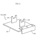
- Fig. 5 illustrates the coasters 13a (13b) on which the underbody 3 is set.
- Each of the coasters 13a (13b) includes a rectangular base 131 for engaging with the rollers 11a of the conveyor 11.
- a pair of body-receiving parts 133 is installed on the upper surface of the base 131 vertically, which is to support the underbody 3.
- the body-receiving parts 133 are spaced to each other widthwise of the base 131 (perpendicularly to transfer direction).
- the width of the base 131 is shorter than the length of the roller 11a.
- One end of the base 131 is equipped with an angle bar 132 fixed by a bolt for preventing the coaster from moving widthwise during transfer. Another angle bar may be fixed at the other end of the base 131.
- the coasters 13a, 13b are arranged to support the front and the rear part of the underbody 3.
- each of the coasters includes two body-receiving parts 133 (see Fig. 5).
- the underbody 3 is supported by the coasters 13a, 13b at four points. A worker pushes the underbody 3 by hand and convey it on the roller conveyor 11.
- the side member spot welding station 1 is equipped with a plurality of locators 16 for locating left and right side members 4.
- locators 16 are provided for each side member 4 (see also Fig. 7), and the locators are spaced to each other in the transfer direction of the assembly line.
- Each locator 16 includes an engaging unit (not shown) for engaging with a predetermined part of the side member 4.
- the engaging unit can be, for example, a clamp mechanism or a suction mechanism.
- the bottom area of the side member 4 is located by the locators 16 when it's spot welded to the underbody 3.
- the locators 16 are smaller than the side member 4 as seen in the vertical direction (vertical direction in Fig. 7) and in the direction parallel to the transfer direction of the assembly line (lateral direction in Fig. 7).
- Each locator 16 is equipped with a lifter 15 including two supporting plates spaced to each other in the transfer direction of the assembly line.
- the lifter 15 is movable in the vertical direction.
- a slide guide 17 (see Fig. 1) is installed, projecting in parallel to the supporting plate.
- a slide base 18 is installed on the slide guide 17. The slide base 18 can move reciprocally along the slide guide 17, by worker's manual operation.
- the lifter 15 can be lowered (and lifted), while supporting the locator 16.
- the locator 16 set on the lifter 15 is moved downward and transferred to the lower slide base 18. Thereafter, the slide base 18 is moved along the slide guide 17 to displace the locator 16 toward the assembly line 2 (forward) or away from the assembly line 2 (backward).
- each locator 16 is equipped with four wheels 20 on its bottom surface. Further, as shown in Fig. 6B, spacers 21 is installed on the bottom surface of the locator 16 for adjusting the height of the locator. On the other hand, spacers 24 that contact with the spacers 21 is installed on the top of the slide base 18.
- the locator 16 includes a plurality of vertically extending holes 22 at its inside, into which locating pins 25 installed on the slide base 18 are inserted.
- the lifter 15 includes a rear end provided with guards 19 and with a stopper 23 with which the wheel 20 contacts for positioning the locator 16 provisionally.
- the position X is the upper limit of the lifter 15 and the top surface of the lifter 15 is flush with the floor level in the position X.
- the position Y is the lower limit.
- the locating pin 25 of the slide base 18 is inserted into the hole 22 of the locator 16, so that the locator 16 is seated on the slide base 18.
- the two supporting plates of the lifter 15 are spaced to each other at a certain distance enough to prevent interference with the slide base 18 during the lowering.
- two locators 16 may be supported by one slide base 18.
- the slide base 18 includes a base 18a, which is equipped with upright locating pins 25 for locating a plurality of locators 16.
- the base 18a is further equipped with a handle 18b, which the worker grabs for moving the slide base 18.
- each locator 16 may also be supported by a respective slide base 18. In this way, the worker can get in between two locators 16 to perform spot welding operation.
- two slide bases 18 are joined to each other by means of a removable connecting rod 26.
- the connecting rod 26 enables the worker to move two slide bases 18 together forwards and backwards.
- the connecting rod 26 may be linear as a whole, but desirably, is a crank having a bending part 26a between the locators 16, as shown.
- the connecting rod 26 does not obstruct the operation at the upper area of the side member 4.
- the bending part 26 is positioned upwards (indicated by chain double-dashed lines in Fig. 10A).
- the slide base 18 may be provided with a angle 27 at the front (at the side facing the conveyor 11), and the angle 27 may contact with a stopper 28.
- the stopper 28 includes a jaw 30, which is operated by an air cylinder 29. The jaw 30 clamps the angle 27, thereby the slide base 18 is held firmly at a determined position.
- the lifter 15 is moved up and down between the above-described positions X and Y (see Fig. 6B) by, for example, a pantograph mechanism similar to the one shown in Fig. 4B.
- a pantograph mechanism similar to the one shown in Fig. 4B.
- the lifter 15 When the lifter 15 is lifted to the position X, its top surface is flush with the floor level. In this position, the locator 16 with the wheels 20 can be easily moved from the floor onto the rear end of the lifter 15. Thereafter, as shown in Fig. 11, the wheel 20 contacts with the stopper 23 to position the locator 16 provisionally (refer also to the state indicated by reference number 1 in Fig. 12).
- the slide base 18 is installed below the locator 16. In this state, when the lifter 15 is lowered (as indicated by reference number 2 in Fig.
- the locator 16 holds the side member 4 and the slide base 18 advances along the slide guide 17 toward the assembly line (as indicated by reference number 3 in Fig. 3). Then, as illustrated by chain double-dashed lines in Fig. 11, the side member 4 is located relative to the underbody 3 that is on standby. In this state, the side member 4 is spot welded to the underbody 3.
- the fixation of the locator 16 to the side member 4 is released and the slide base 18 is retreated at a determined distance (as indicated by reference number 4 in Fig. 12).
- the locator 16 holds next side member 4 that is to be spot welded to next underbody 3.
- the slide base 18 and the previous locator 16 are positioned at the above-described "standby position", and in this state, the lifter 15 is lifted (as indicated by reference number 5 in Fig. 12).
- the wheel 20 of the locator 16 rides on the lifter 15, and when the lifter 15 is further lifted, the locator 16 is detached from the slide base 18.
- the wheel 20 is used to move the locator 16 from the lifter 15 to the floor level. Thereafter, the locator 16 is returned to a locator stock area near the car body assembly line 2.
- the slide base 18 is retreated to the rear end of the slide guide 17 (as indicated by reference number 6 in Fig. 12).
- another locator 16 is set on the rear end of the lifter 15 that is at the upper limit (the position X in Fig. 6B). Thereafter, the lifter 15 is lowered in order to transfer the locator 16 to the slide base 18.
- the locators used in the above procedure are more compact than conventional one. Therefore, a plurality (one type or various types) of locators can be stored near the car body assembly line 2 without obstructing the operation. Further, the worker can move the locator 16 easily as the wheels 20 are installed on the bottom area of the locator 16.
- conventional large jig is stored at a place apart from the car body assembly line 2, and transferred to the side member spot welding station 1 from the storage, using a special transfer line, if necessary. According to the present invention, such transfer line for jig is unnecessary.
- each locator 16 is used for each side member 4, however, the present invention is not limited to this.
- three (or more) locators 16 are used for one side member 4 as shown in Fig. 6A .
- each locator may have respective slide guide 17 and slide base 18.
- a plurality of locators may share one elongated slide base.
- the underbody 3 and the side member 4 spot welded to each other are transferred from the spot welding station 1 to the roof panel pre-setting station 6.
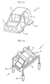
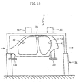
- a roof panel 31 is pre-set and laid over the top of the side members 4 (see Fig. 13). Further at the station 6, the underbody 3 and the side members 4 are re-spot welded.
- the roof panel 31 is pre-set by the worker manually or using any device such as a hoist.
- the roof panel spot welding station 7 is equipped with a pair of frames 34 at the sides of the transfer line. A pair of removable Seasted jigs 35, 36 are installed and laid between the upsides of the frames, being spaced to each other in the transfer direction. Further, though not shown in the figure, the station 7 is equipped with a hoist for transferring the jigs 35, 36 and with a spot welding machine for pre-fixing the roof panel 31 to the side member 4.
- the roof panel 31 is specified as a part to be fixed to the side member 4, the present invention is not limited to this. The present invention can be also applied to fix a part (such as a header inner and a frame back, for example) to be laid across the side members 4, instead of a roof panel 31.
- reinforcement may be installed across the two frames 34.
- the frame 34 includes vertical bars spaced to each other in the transfer direction and a horizontal bar connecting the vertical bars.
- the horizontal bar includes a top surface equipped with a clamp mechanism for installing the removable joisted jigs 35, 36.
- the joints 35, 36 include a bottom side equipped with a pair of clamp arms 39.
- the clamp arm 39 is operated manually or by an air cylinder, for connecting an upper welding end of the side member 4 to a welding end of the roof panel 31.
- the roof panel 31 is located on the side members 4, whereby a front window opening 40 and a rear window opening 41 are formed. According to the present invention, these openings are not distorted and can be formed as desired. It is because the roof panel 31 and the side members 4 are properly located to each other as the roof panel 31 and the side members 4 are located relatively to a common immovable ground. Specifically, the side member 4 is already re-spot welded to the underbody 3 at the previous station 6. Further, the coasters 13a, 13b supporting the underbody 3 are placed at an immovable system including the ground. Thus, the side member 4 is, though indirectly, fixed to the immovable system.
- the roof panel 31 can be also fixed to the same immovable system by means of the frame 34 (and the joisted jigs 35, 36).
- the roof panel 31 and the side members 4 can be firmly located to each other, whereby the front window opening 40 and the rear window opening 41 can be formed as desired.
- the joisted jigs 35, 36 maybe stored at one of the plat forms 42-1, 42-2.
- jigs to be attached to the frame 34 are stored at the platform 42-1, and jigs already used and removed from the frame 34 are stored at the platform 42-2. In this way, replacement of the jigs can be effectively performed.
- the joisted jigs 35, 36 are installed at the front and rear areas of roof panel 31, with a certain distance between themselves, which provides a wide working space. Therefore, welding operation by a worker is much easier, and a spot welding machine and a re-spot welding machine can be installed in the same area. Further, the easy access to the welding points enables to use a welding machine with relatively short reach.
- Fig. 18A shows a transferring system (indicated by reference number 50) for replacing the joisted jigs 35, 36.
- the reference number 51 indicates a ceiling rail 51 from which a hoist 52 is hung.
- the hoist 52 elevates and lowers a movable rail (see Fig. 18B).
- a fixed rail 54 is installed below the ceiling rail 51 with a space 55 in between where the movable rail 53 is inserted.
- the fixed rail 54 is furnished with two stoppers 56 for preventing the movable rail 53 from elevating beyond the fixed rail.
- the stoppers 56 are installed on the upper surface of the fixed rail 54 and protrude horizontally from the end of the fixed rail. As shown in Fig.
- the movable rail 53 and the fixed rail 54 are joined and form, as a whole, one transfer path.
- two pulleys 57 connected each other can move along the transfer path.
- a rod of a predetermined rigidity or other material can be used (this structure can give a certain space between two pulleys 57).
- the joisted jig 35 (36) is hung from the pulleys 57.
- the pulleys 57 can move along the path of the movable rail 53 and the fixed rail 54.
- the pulleys 57 with hung joisted jig 35 (36) is transferred along the fixed rail 54 to the movable rail 53. Thereafter, as shown in Fig. 18B, the movable rail 53 is lowered by the hoist 52, and the joisted jig 35 (36) is positioned on the frames 34.
- a rail sway prevention mechanism 60 as shown in Figs. 19A, 19B is furnished for preventing the movable rail 53 from swaying while lowering the joisted jig 35 (36).
- the illustratedmechanism 60 includes a fixed guide 61 installed on and hung from the ceiling, an upright bar 62 installed on the movable rail 53, and a rotatable roller 63 installed at each upright bar 62. As shown in Fig. 19B, the roller 63 rolls at the inner wall of the fixed guide 61 as the upright bar 62 moves up and down.
- the pulleys 57 may fall out of the movable rail 53.
- stoppers 58 as shown in Figs.
- the stopper 58 turns on the pivot, and when the movable rail 53 is lowered, the stopper 58 takes a position as shown in Fig. 20A due to biasing force of a spring (not shown).
- a spring not shown
- the stopper 58 is brought into a horizontal posture, whereby the pulley 57 can move from the movable rail 53 to the fixed rail 54, and vice versa.
- Fig. 21 illustrates a locating mechanism 70 for attaching the joisted jig 35 (36) to the frame 34.
- a locating pin 71 protrudes from the top surface of the frame 34, while the warsted jig 35 (36) includes a hole 72 in which the locating pin 71 to be inserted. After the locating pin 71 fits in the hole 72, a clamp arm 73 is used to fix the joisted jig 35 (36) to the frame 34.
- Figs. 22A and 22B illustrate a locating mechanism 80 which may be installed near the car body assembly line.
- the mechanism 80 includes an upper part 81 and a lower part 82, and the lower part 82 is fixed to the floor while the upper part 81 is rotatable and joined to the lower part 82 with a pin 83.
- the lower part 82 is equipped with an air cylinder 84, while the upper part 81 is connected to a drive rod of the air cylinder 84.
- the upper part 81 can be placed at a vertical position (illustrated by solid lines) or an inclined position (illustrated by broken lines) by moving the drive rod out from and into the main body of air cylinder.
- the upper part 81 is furnished with two spacers 85 and one locating pin 86.
- the inclining upper part 81 prevents the interference between an object transferred along the assembly line and the locating mechanism 80.
- the inclined position of the upper part 81 enables proper transfer of the coaster 13c along the assembly line without being obstructed by the locating mechanism 80.
- another locating mechanism of different type may be installed.
- the additional mechanism can be installed at a space S near the mechanism 80 (or any other place).
Abstract
Description
- The present invention relates to a method of assembling a motor vehicle body. Specifically, the present invention relates to a method for pre-fixing bridging parts, such as a roof panel, a header inner and a frame back, to the left and right side members, which are welded to an underbody of a car.
- A car body includes main parts such as an underbody, left and right side members, and a roof panel. For assembling a car body using these parts, firstly the parts to be assembled are positioned relative to each other, using locating jigs, etc. Next, the parts are fixed by spot welding, thereafter re-spot welded to be fixed completely.
- A conventional method of assembling a car body utilizes a significantly large locating jig for locating the main parts. For example, a jig used to position the roof panel is larger than the roof panel itself. Such locating jig is installed above the car body assembly line and is movable up and down. When pre-setting the roof panel on the left and right side members, the roof panel is transferred to a position below the locating jig, and set into the locating jig. Next, the locating jig is lowered to position both edges of the roof panel on the upper ends of the side members. Finally, in this manner, the roof panel is spot welded to the side member.
- The above-described conventional locating jigs for roof panel are large and heavy, thus cause various problems. For example, conventional jigs tend to require large facility investment at the beginning. Further, it is very complicated to replace the locating jigs corresponding to types of cars to be manufactured. Specifically, the used locating jig should be removed from a hoist and another jig should be set in thereto. During this troublesome operation, the production line may be completely stopped.
- Further, a motor for lifting the jig should bear a large load due to the large and heavy locating jig. Thus, a movable portion of the motor may suffer trouble such as wear, so that constant maintenance is needed for working the motor properly. Still further, it is difficult to perform precise location by using large and heavy locating jigs efficiently.
- The present invention has been proposed under the above-described circumstances. It is therefore an object of the present invention to realize reduction in size and weight of the locating jig used for a bridging part such as a roof panel, a header board and a frame back.
- The present invention provides a method of assembling a car body by spot welding a bridging part to a pair of side members fixed to an underbody of a car. The method comprising the steps of: placing a pair of frames at sides of a transfer line for transferring the underbody and the side members; attaching a plurality of detachable joisted-locating jigs to the frame for locating the side member and the bridging part; and spot welding the side members to the bridging part, with the side members and the bridging part being clamped by the joisted-locating jigs. An appropriate transfer system is employed to convey the joisted-locating jig from the frame to a first stock area and to convey another joisted-locating jig from a second stock area to the frame for performing a joisted-locating jig change.
- The joisted-locating jig can be made lighter and smaller than conventional locating jig for roof panel. Thus, initial facility investment may be reduced. Further, the joisted-locating jig according to the present invention does not obstruct the assembly operation even if it is stored near the transfer line.
- Preferably, the frame and the joisted-locating jig are positioned by a clamp mechanism.
- Preferably, the transfer system includes a motor, a movable rail moved up and down by the motor, a fixed rail to be combined with the movable rail, and a pulley movable along the movable rail and the fixed rail. The joisted-locating jig is hung from the pulley.
- Preferably, a sway prevention mechanism is provided for preventing the movable rail from swaying when the movable rail is apart from the fixed rail.
- Preferably, the sway prevention mechanism includes a pair of vertical rods attached to the movable rail and a pair of fixed guides fixed to immovable structure. The vertical rod moves relative to the fixed guide be means of a roller.
- Preferably, the movable rail is equipped with a fall-out prevention device, which is to prevent the pulley from falling out of the movable rail.
- Preferably, the fall-out prevention device includes a stopper that turns on the pivot previously determined. The stopper is displaceable in the span between engaging and disengaging points of the stopper and the pulley.
-
- Fig. 1 is a schematic perspective view illustrating a spot welding station for spot welding a side member of a car to an underbody.
- Fig. 2 is a schematic plan view illustrating a structure of a car body assembly line.
- Fig. 3 is a schematic view illustrating the underbody supported by two transfer coasters, and the side member to be fixed to the underbody.
- Fig. 4A is a schematic side view illustrating a roller conveyor for transferring the underbody shown in Fig. 3.
- Fig. 4B is a schematic side view illustrating an elevating mechanism for adjusting the height of the roller conveyor.
- Fig. 5 is a schematic perspective view illustrating the coaster.
- Fig. 6A illustrates an example where three locators are used for one side member.
- Fig. 6B is a section view taken along a line A-A in Fig. 6A.
- Fig. 7 is a side view illustrating the side member at the spot welding station.
- Fig. 8 is a schematic view illustrating a wheel installed on the locator for the side member, and a portion of a lifter on which the wheel is installed.
- Fig. 9 is a perspective view illustrating an upper portion of a slide base for placing two locators together.
- Fig. 10A is a side view illustrating an example of a connecting rod for joining two slide bases.
- Fig. 10B is a front view illustrating a locating clamp mechanism for the slide base.
- Fig. 11 is a schematic view illustrating methods for placing the locator on the slide base and for locating the side member to the underbody using the locator.
- Fig. 12 is a schematic view illustrating a method for replacing the locators.
- Fig. 13 is a schematic perspective view illustrating the posture of the car body at the roof panel pre-setting station.
- Fig. 14 is a schematic perspective view illustrating the roof panel pre-setting station.
- Fig. 15 is a schematic side view of the roof panel pre-setting station.
- Fig. 16 is a schematic front view of the roof panel pre-setting station.
- Fig. 17 is a schematic plan view of the roof panel pre-setting station.
- Fig. 18A is a schematic front view illustrating a transfer system for joisted-locating jigs used at the roof panel pre-setting station.
- Fig. 18B is a view illustrating a movable rail of the transfer system in a lower position.
- Fig. 19A is a schematic view illustrating a sway prevention mechanism for the movable rail shown in Fig. 18B.
- Fig. 19B is a side view illustrating main parts of the sway prevention mechanism.
- Fig. 20A is a front view illustrating falling-out prevention device for pulley, installed at the movable rail shown in Fig. 18B.
- Fig. 20B is a view illustrating a stopper of falling-out prevention device for pulley, in a release position.
- Fig. 21 is a view illustrating a locating clamp mechanism for the joisted-locating jigs.
- Fig. 22A is a front view illustrating the movement of a locating mechanism provided near the transfer line.
- Fig. 22B is a side view illustrating a space to install any additional locating mechanism.
-
- As follows, a successful example of this invention is described in detail, with attached drawings being referred.
- Fig. 1 is a schematic view illustrating a side member
spot welding station 1. The side memberspot welding station 1 is installed at a predetermined place in a car body assembly line 2 (see Fig. 2). The carbody assembly line 2 includes an underbody loading station (not shown) installed upstream of the side member spot welding station 1 (the left side in Fig. 2). In this underbody loading station, anunderbody 3 is set oncoasters underbody 3, including a rear portion facing downstream of the carbody assembly line 2 for example, is carried by a roller conveyor 11 (see Fig. 4), to be sent to an underbody setting station 5 (#0) and to the side member spot welding station 1 (#1). Theroller conveyor 11 includes a plurality ofrotatable rollers 11a, each spaced to each other at a predetermined distance in the transfer direction of theunderbody 3 and so on. - As shown in Fig. 2, the downstream side of the side member spot welding station 1 (#1) is provided with a roof panel pre-setting station 6 (#2) and a roof panel spot welding station 7 (#3). In the roof
panel pre-setting station 6, a roof panel is pre-set on aside member 4, and theside member 4 is re-spot welded to theunderbody 3. A roof panel re-spot welding station (#4) is install next to the roof panel spot welding station 7 (#3) on its downstream side. When many points of the roof panel is to be re-spot welded, as shown, a plurality of roof panel re-spot welding stations 8-1 (#4)-8-3 (#6) are installed so that workload for re-spot welding per one worker is not increased too much. The downstream side of the roof panel re-spot welding station is equipped with a re-spot welding station 9 (#7) having a welding robot, and also equipped with an unloading station 10 (#8). - In the side member
spot welding station 1 and the roofpanel pre-setting station 6, the height of theunderbody 3 may need to be adjusted to corresponding types of cars. For this adjustment, each of thestations conveyor 11. As shown in Fig. 4B, this elevating mechanism is apantograph mechanism 14, for example. Thepantograph mechanism 14 includes a plurality of supportingmembers 14a that are pivot-able and joined by apin 14, anair cylinder 14c, and a slidingmechanism 14d. The bottom end of one of the supportingmembers 14a is reciprocally moved in horizontal direction by theair cylinder 14c be means of the slidingmechanism 14d, thereby lifting and lowering theconveyor 11. - Fig. 5 illustrates the
coasters 13a (13b) on which theunderbody 3 is set. Each of thecoasters 13a (13b) includes arectangular base 131 for engaging with therollers 11a of theconveyor 11. A pair of body-receivingparts 133 is installed on the upper surface of the base 131 vertically, which is to support theunderbody 3. The body-receivingparts 133 are spaced to each other widthwise of the base 131 (perpendicularly to transfer direction). The width of thebase 131 is shorter than the length of theroller 11a. One end of thebase 131 is equipped with anangle bar 132 fixed by a bolt for preventing the coaster from moving widthwise during transfer. Another angle bar may be fixed at the other end of thebase 131. - As shown in Fig. 4A, the
coasters underbody 3. As described above, each of the coasters includes two body-receiving parts 133 (see Fig. 5). Thus, theunderbody 3 is supported by thecoasters underbody 3 by hand and convey it on theroller conveyor 11. - As shown in Fig. 1, the side member
spot welding station 1 is equipped with a plurality oflocators 16 for locating left andright side members 4. In the illustrated example, twolocators 16 are provided for each side member 4 (see also Fig. 7), and the locators are spaced to each other in the transfer direction of the assembly line. Eachlocator 16 includes an engaging unit (not shown) for engaging with a predetermined part of theside member 4. The engaging unit can be, for example, a clamp mechanism or a suction mechanism. The bottom area of theside member 4 is located by thelocators 16 when it's spot welded to theunderbody 3. As shown in Fig. 7, thelocators 16 are smaller than theside member 4 as seen in the vertical direction (vertical direction in Fig. 7) and in the direction parallel to the transfer direction of the assembly line (lateral direction in Fig. 7). - Each
locator 16 is equipped with alifter 15 including two supporting plates spaced to each other in the transfer direction of the assembly line. Thelifter 15 is movable in the vertical direction. Below eachlifter 15, a slide guide 17 (see Fig. 1) is installed, projecting in parallel to the supporting plate. Aslide base 18 is installed on theslide guide 17. Theslide base 18 can move reciprocally along theslide guide 17, by worker's manual operation. - The
lifter 15 can be lowered (and lifted), while supporting thelocator 16. Thelocator 16 set on thelifter 15 is moved downward and transferred to thelower slide base 18. Thereafter, theslide base 18 is moved along theslide guide 17 to displace thelocator 16 toward the assembly line 2 (forward) or away from the assembly line 2 (backward). - As can be seen from Fig. 6B, 11 and 12, each
locator 16 is equipped with fourwheels 20 on its bottom surface. Further, as shown in Fig. 6B,spacers 21 is installed on the bottom surface of thelocator 16 for adjusting the height of the locator. On the other hand, spacers 24 that contact with thespacers 21 is installed on the top of theslide base 18. Thelocator 16 includes a plurality of vertically extendingholes 22 at its inside, into which locating pins 25 installed on theslide base 18 are inserted. As shown in Fig. 8, thelifter 15 includes a rear end provided withguards 19 and with astopper 23 with which thewheel 20 contacts for positioning thelocator 16 provisionally. - As shown in Fig. 6B, the position X is the upper limit of the
lifter 15 and the top surface of thelifter 15 is flush with the floor level in the position X. On the other hand, the position Y is the lower limit. When lowering to the position Y, the locatingpin 25 of theslide base 18 is inserted into thehole 22 of thelocator 16, so that thelocator 16 is seated on theslide base 18. As can be seen from the figure, the two supporting plates of thelifter 15 are spaced to each other at a certain distance enough to prevent interference with theslide base 18 during the lowering. - According to the present invention, as shown in Fig. 9, two
locators 16 may be supported by oneslide base 18. In this structure, theslide base 18 includes abase 18a, which is equipped with upright locating pins 25 for locating a plurality oflocators 16. Thebase 18a is further equipped with ahandle 18b, which the worker grabs for moving theslide base 18. As shown in Figs. 10A and 10B, eachlocator 16 may also be supported by arespective slide base 18. In this way, the worker can get in between twolocators 16 to perform spot welding operation. In the illustrated example, twoslide bases 18 are joined to each other by means of a removable connectingrod 26. The connectingrod 26 enables the worker to move twoslide bases 18 together forwards and backwards. The connectingrod 26 may be linear as a whole, but desirably, is a crank having a bendingpart 26a between thelocators 16, as shown. In the form, when the bendingpart 26a is positioned downwards (indicated by solid lines in Fig. 10A), the connectingrod 26 does not obstruct the operation at the upper area of theside member 4. When working on the lower area of theside member 4, the bendingpart 26 is positioned upwards (indicated by chain double-dashed lines in Fig. 10A). - As shown in Fig. 10B, the
slide base 18 may be provided with aangle 27 at the front (at the side facing the conveyor 11), and theangle 27 may contact with astopper 28. Desirably, thestopper 28 includes ajaw 30, which is operated by anair cylinder 29. Thejaw 30 clamps theangle 27, thereby theslide base 18 is held firmly at a determined position. - The
lifter 15 is moved up and down between the above-described positions X and Y (see Fig. 6B) by, for example, a pantograph mechanism similar to the one shown in Fig. 4B. When thelifter 15 is lifted to the position X, its top surface is flush with the floor level. In this position, thelocator 16 with thewheels 20 can be easily moved from the floor onto the rear end of thelifter 15. Thereafter, as shown in Fig. 11, thewheel 20 contacts with thestopper 23 to position thelocator 16 provisionally (refer also to the state indicated byreference number 1 in Fig. 12). Theslide base 18 is installed below thelocator 16. In this state, when thelifter 15 is lowered (as indicated byreference number 2 in Fig. 12), in the middle of lowering the locatingpin 25 of theslide base 18 is fitted into thehole 25 of thelocator 16, whereby thelocator 16 is engaged with and located on theslide base 18. When thelifter 15 is further lowered, thewheel 20 of thelocator 16 is detached from thelifter 15, and thelocator 16 is finally seated on theslide base 18. - Next, the
locator 16 holds theside member 4 and theslide base 18 advances along theslide guide 17 toward the assembly line (as indicated byreference number 3 in Fig. 3). Then, as illustrated by chain double-dashed lines in Fig. 11, theside member 4 is located relative to theunderbody 3 that is on standby. In this state, theside member 4 is spot welded to theunderbody 3. - After welding, the fixation of the
locator 16 to theside member 4 is released and theslide base 18 is retreated at a determined distance (as indicated byreference number 4 in Fig. 12). In this position (hereinafter referred to as "standby position"), thelocator 16 holdsnext side member 4 that is to be spot welded tonext underbody 3. - When an
underbody 3 of a type different from the previous underbody is transferred to the side memberspot welding station 1, the previous locator needs to be replaced with a locator of another type. The procedure of the replacement is described below. - First, the
slide base 18 and theprevious locator 16 are positioned at the above-described "standby position", and in this state, thelifter 15 is lifted (as indicated byreference number 5 in Fig. 12). During lifting, thewheel 20 of thelocator 16 rides on thelifter 15, and when thelifter 15 is further lifted, thelocator 16 is detached from theslide base 18. After thelifter 15 is lifted up to be flush with the floor level, thewheel 20 is used to move thelocator 16 from thelifter 15 to the floor level. Thereafter, thelocator 16 is returned to a locator stock area near the carbody assembly line 2. - After the
lifter 15 is lifted and theprevious locator 16 is detached from theslide base 18, theslide base 18 is retreated to the rear end of the slide guide 17 (as indicated byreference number 6 in Fig. 12). On the other hand, anotherlocator 16 is set on the rear end of thelifter 15 that is at the upper limit (the position X in Fig. 6B). Thereafter, thelifter 15 is lowered in order to transfer thelocator 16 to theslide base 18. - The locators used in the above procedure are more compact than conventional one. Therefore, a plurality (one type or various types) of locators can be stored near the car
body assembly line 2 without obstructing the operation. Further, the worker can move thelocator 16 easily as thewheels 20 are installed on the bottom area of thelocator 16. On the contrary, conventional large jig is stored at a place apart from the carbody assembly line 2, and transferred to the side memberspot welding station 1 from the storage, using a special transfer line, if necessary. According to the present invention, such transfer line for jig is unnecessary. - In the example shown in Fig. 1, two
locators 16 are used for eachside member 4, however, the present invention is not limited to this. For example, three (or more)locators 16 are used for oneside member 4 as shown in Fig. 6A . In this case, each locator may haverespective slide guide 17 andslide base 18. Alternatively, a plurality of locators may share one elongated slide base. - The
underbody 3 and theside member 4 spot welded to each other are transferred from thespot welding station 1 to the roofpanel pre-setting station 6. At thestation 6, aroof panel 31 is pre-set and laid over the top of the side members 4 (see Fig. 13). Further at thestation 6, theunderbody 3 and theside members 4 are re-spot welded. Theroof panel 31 is pre-set by the worker manually or using any device such as a hoist. - After the pre-setting a
roof panel 31, it is spot welded at the roof panelspot welding station 7. As shown in Fig. 14, the roof panelspot welding station 7 is equipped with a pair offrames 34 at the sides of the transfer line. A pair of removablejoisted jigs station 7 is equipped with a hoist for transferring thejigs roof panel 31 to theside member 4. In the illustrated example, though theroof panel 31 is specified as a part to be fixed to theside member 4, the present invention is not limited to this. The present invention can be also applied to fix a part (such as a header inner and a frame back, for example) to be laid across theside members 4, instead of aroof panel 31. Alternatively, reinforcement may be installed across the twoframes 34. - As shown in Fig. 15, the
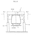
frame 34 includes vertical bars spaced to each other in the transfer direction and a horizontal bar connecting the vertical bars. The horizontal bar includes a top surface equipped with a clamp mechanism for installing the removablejoisted jigs - As shown in Fig. 16, the joisted jigs 35, 36 include a bottom side equipped with a pair of
clamp arms 39. Theclamp arm 39 is operated manually or by an air cylinder, for connecting an upper welding end of theside member 4 to a welding end of theroof panel 31. - As shown in Fig. 14 or 15, the
roof panel 31 is located on theside members 4, whereby afront window opening 40 and arear window opening 41 are formed. According to the present invention, these openings are not distorted and can be formed as desired. It is because theroof panel 31 and theside members 4 are properly located to each other as theroof panel 31 and theside members 4 are located relatively to a common immovable ground. Specifically, theside member 4 is already re-spot welded to theunderbody 3 at theprevious station 6. Further, thecoasters underbody 3 are placed at an immovable system including the ground. Thus, theside member 4 is, though indirectly, fixed to the immovable system. On the other hand, theroof panel 31 can be also fixed to the same immovable system by means of the frame 34 (and the joisted jigs 35, 36). As a result, theroof panel 31 and theside members 4 can be firmly located to each other, whereby thefront window opening 40 and the rear window opening 41 can be formed as desired. - As the
clamp arms 39 installed atjoisted jigs different clamps arm 39 are necessary for respective car types. In the illustrated example, whole units ofjoisted jigs joisted jigs frame 34. Thus, as shown in Figs. 16 and 17, it is desirable to store the joisted jigs 35, 36 at platforms 42-1, 42-2 (having height almost the same as the frame 34) installed adjacent to the car body assembly line. - The joisted jigs 35, 36 maybe stored at one of the plat forms 42-1, 42-2. In this case, for example, jigs to be attached to the
frame 34 are stored at the platform 42-1, and jigs already used and removed from theframe 34 are stored at the platform 42-2. In this way, replacement of the jigs can be effectively performed. - The joisted jigs 35, 36 are installed at the front and rear areas of
roof panel 31, with a certain distance between themselves, which provides a wide working space. Therefore, welding operation by a worker is much easier, and a spot welding machine and a re-spot welding machine can be installed in the same area. Further, the easy access to the welding points enables to use a welding machine with relatively short reach. - Conventional jigs for roof panel are larger than a roof panel it self, thereby requiring large facility investment and much time for replacing jigs. Contrary, the jigs according to the present invention are elongated and thus don't take much space, thereby not obstructing the operation even if it is stored near the car body assembly line. Further, as described above, replacement of the jigs is much easier.
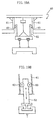
- Fig. 18A shows a transferring system (indicated by reference number 50) for replacing the joisted jigs 35, 36. As shown, the
reference number 51 indicates aceiling rail 51 from which a hoist 52 is hung. The hoist 52 elevates and lowers a movable rail (see Fig. 18B). A fixedrail 54 is installed below theceiling rail 51 with aspace 55 in between where themovable rail 53 is inserted. The fixedrail 54 is furnished with twostoppers 56 for preventing themovable rail 53 from elevating beyond the fixed rail. Thestoppers 56 are installed on the upper surface of the fixedrail 54 and protrude horizontally from the end of the fixed rail. As shown in Fig. 18A, themovable rail 53 and the fixedrail 54 are joined and form, as a whole, one transfer path. In the illustrated example, twopulleys 57 connected each other can move along the transfer path. For connecting twopulleys 57, a rod of a predetermined rigidity or other material can be used (this structure can give a certain space between two pulleys 57). The joisted jig 35 (36) is hung from thepulleys 57. Thepulleys 57 can move along the path of themovable rail 53 and the fixedrail 54. - As shown in Fig. 18A, the
pulleys 57 with hung joisted jig 35 (36) is transferred along the fixedrail 54 to themovable rail 53. Thereafter, as shown in Fig. 18B, themovable rail 53 is lowered by the hoist 52, and the joisted jig 35 (36) is positioned on theframes 34. A railsway prevention mechanism 60 as shown in Figs. 19A, 19B is furnished for preventing themovable rail 53 from swaying while lowering the joisted jig 35 (36). Theillustratedmechanism 60 includes a fixedguide 61 installed on and hung from the ceiling, anupright bar 62 installed on themovable rail 53, and arotatable roller 63 installed at eachupright bar 62. As shown in Fig. 19B, theroller 63 rolls at the inner wall of the fixedguide 61 as theupright bar 62 moves up and down. - When the
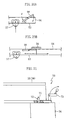
movable rail 53 is lowered (see Fig. 18B), thepulleys 57 may fall out of themovable rail 53. To prevent the falling, for example,stoppers 58 as shown in Figs. Thestopper 58 turns on the pivot, and when themovable rail 53 is lowered, thestopper 58 takes a position as shown in Fig. 20A due to biasing force of a spring (not shown). As shown in Fig. 20B, when themovable rail 53 is lifted up and fits in thespace 55 of the fixedrail 54, the upper end of thestopper 58 is pushed down by thestopper 56. In this way, thestopper 58 is brought into a horizontal posture, whereby thepulley 57 can move from themovable rail 53 to the fixedrail 54, and vice versa. - Fig. 21 illustrates a
locating mechanism 70 for attaching the joisted jig 35 (36) to theframe 34. In the illustrated example, a locatingpin 71 protrudes from the top surface of theframe 34, while the joisted jig 35 (36) includes ahole 72 in which the locatingpin 71 to be inserted. After the locatingpin 71 fits in thehole 72, aclamp arm 73 is used to fix the joisted jig 35 (36) to theframe 34. - Figs. 22A and 22B illustrate a
locating mechanism 80 which may be installed near the car body assembly line. Themechanism 80 includes anupper part 81 and alower part 82, and thelower part 82 is fixed to the floor while theupper part 81 is rotatable and joined to thelower part 82 with apin 83. As shown in Fig. 22A, thelower part 82 is equipped with anair cylinder 84, while theupper part 81 is connected to a drive rod of theair cylinder 84. Theupper part 81 can be placed at a vertical position (illustrated by solid lines) or an inclined position (illustrated by broken lines) by moving the drive rod out from and into the main body of air cylinder. Theupper part 81 is furnished with twospacers 85 and one locatingpin 86. - As described above, the inclining
upper part 81 prevents the interference between an object transferred along the assembly line and thelocating mechanism 80. In case, for example, of acoaster 13c that includes body-receivingparts 133a protruding in lateral direction as illustrated by chain double-dashed lines in Fig. 22A, the inclined position of theupper part 81 enables proper transfer of thecoaster 13c along the assembly line without being obstructed by the locatingmechanism 80. - According to the present invention, in addition to the above-described
locating mechanism 80, another locating mechanism of different type may be installed. In this case, as shown in Fig. 22B, the additional mechanism can be installed at a space S near the mechanism 80 (or any other place). - The present invention being thus described, it is obvious that the same invention can be modified in various ways. Such modifications should not be regarded as a different idea from this invention or to be out of its scope, and all such modifications as would be obvious to those skilled in the art are intended to be included in the scope of the appended claims.
Claims (7)
- A method of assembling a car body by spot welding a bridging part to a pair of side members fixed to an underbody of a car, the method comprising the steps of:wherein a transfer system is employed to convey the joisted-locating jig from the frame to a first stock area and to convey another joisted-locating jig from a second stock area to the frame for performing a joisted-locating jig change.installing a pair of frames at sides of a transfer line for transferring the underbody and the side members;attaching a plurality of movable joisted-locating jigs to the frame for locating the side members and the bridging part; andspot welding the side members to the bridging part, with the side members and the bridging part clamped by the joisted-locating jigs;
- The method of assembling a car body according to claim 1, wherein the frame and the joisted-locating jig are located and fixed by a clamp mechanism.
- The method of assembling a car body according to claim 1, wherein the transfer system includes a motor, a movable rail moved up and down by the motor, a fixed rail to be combined with the movable rail, and a pulley movable along the movable rail and the fixed rail, the joisted-locating jig being hung from the pulley.
- The method of assembling a car body according to claim 3, wherein a sway prevention mechanism is furnished for preventing the movable rail from swaying when the movable rail and the fixed rail are disconnected.
- The method of assembling a car body according to claim 4, wherein the sway prevention mechanism includes a pair of vertical rods attached to the movable rail and a pair of fixed guides fixed to an immovable structure, the vertical rods being movable relative to the fixed guide via a roller.
- The method of assembling a car body according to claim 3, wherein a fall prevention mechanism is provided at the movable rail for preventing the pulley from falling out of the movable rail.
- The method of assembling a car body according to claim 6, wherein the fall prevention mechanism includes a stopper that turns on the predetermined pivot, the stopper being movable between a position at which the stopper engages with the pulley and a position at which the stopper is disengaged from the pulley.
Applications Claiming Priority (3)
| Application Number | Priority Date | Filing Date | Title |
|---|---|---|---|
| JP2002307059 | 2002-10-22 | ||
| JP2002307059 | 2002-10-22 | ||
| PCT/JP2003/013337 WO2004037635A1 (en) | 2002-10-22 | 2003-10-17 | Method of assembling motor vehicle body |
Publications (3)
| Publication Number | Publication Date |
|---|---|
| EP1559642A1 true EP1559642A1 (en) | 2005-08-03 |
| EP1559642A4 EP1559642A4 (en) | 2006-04-05 |
| EP1559642B1 EP1559642B1 (en) | 2007-12-12 |
Family
ID=32170929
Family Applications (1)
| Application Number | Title | Priority Date | Filing Date |
|---|---|---|---|
| EP03754174A Expired - Fee Related EP1559642B1 (en) | 2002-10-22 | 2003-10-17 | Method of assembling motor vehicle body |
Country Status (8)
| Country | Link |
|---|---|
| US (1) | US7608801B2 (en) |
| EP (1) | EP1559642B1 (en) |
| JP (1) | JPWO2004037635A1 (en) |
| KR (1) | KR100596564B1 (en) |
| CN (1) | CN100340448C (en) |
| AU (1) | AU2003273042A1 (en) |
| DE (1) | DE60318098T2 (en) |
| WO (1) | WO2004037635A1 (en) |
Families Citing this family (8)
| Publication number | Priority date | Publication date | Assignee | Title |
|---|---|---|---|---|
| DE202004017881U1 (en) * | 2004-11-17 | 2006-03-23 | Kuka Schweissanlagen Gmbh | handling device |
| CN100400362C (en) * | 2006-04-10 | 2008-07-09 | 江苏天奇物流系统工程股份有限公司 | Friction plate prizing mechanical lifting gear |
| KR100887970B1 (en) * | 2007-11-15 | 2009-03-09 | 기아자동차주식회사 | Device for assembling body panel |
| US8141252B2 (en) | 2008-05-23 | 2012-03-27 | Nucor Corporation | Rigging table for assembling trusses and method of use thereof |
| NZ598951A (en) * | 2009-10-30 | 2013-05-31 | Siemens Ag | Flow line and method of operating an assembly line consisting of multiple connected trailer units. |
| CN106394730B (en) * | 2016-12-12 | 2018-05-29 | 北京新能源汽车股份有限公司 | A kind of automobile assembly system |
| CN108945165B (en) * | 2018-07-16 | 2020-08-25 | 北京福田戴姆勒汽车有限公司 | Automobile body assembly fixture |
| CN109702391B (en) * | 2019-01-07 | 2023-08-08 | 浙江威思智能装备有限公司 | Mounting mechanism and mounting method for workbench of multi-station servo hot forging forming machine |
Family Cites Families (13)
| Publication number | Priority date | Publication date | Assignee | Title |
|---|---|---|---|---|
| JPS53151007U (en) | 1977-04-30 | 1978-11-28 | ||
| JPS6112474A (en) * | 1984-06-26 | 1986-01-20 | Toyota Motor Corp | Vehicle body assembling device |
| JPH0631037B2 (en) * | 1985-11-06 | 1994-04-27 | 日産自動車株式会社 | Car assembly method |
| JPH0678072B2 (en) * | 1988-11-25 | 1994-10-05 | トヨタ車体株式会社 | Assembly method of car body |
| JPH09249168A (en) * | 1996-03-19 | 1997-09-22 | Daifuku Co Ltd | Car body temporary assembling method |
| ATE206982T1 (en) * | 1997-03-22 | 2001-11-15 | Thyssenkrupp Technologies Ag | METHOD AND DEVICE FOR FEEDING, CLAMPING AND PROCESSING, IN PARTICULAR FOR GEOMETRIC WELDING OF VEHICLE BODY COMPONENTS IN A PROCESSING STATION |
| FI112334B (en) | 1997-04-08 | 2003-11-28 | Abb Research Ltd | Procedure and arrangement for assembly of car body |
| US5972112A (en) * | 1997-10-03 | 1999-10-26 | Acco Systems, Inc. | Dip tank workpiece carrier with rocking frame |
| US5943768A (en) * | 1997-10-08 | 1999-08-31 | Valiant Machine & Tool Inc. | Automotive framing system |
| US20030037432A1 (en) * | 2001-08-21 | 2003-02-27 | Mcnamara Jeffrey S. | Automotive body component positioning method and apparatus |
| US6595407B2 (en) * | 2001-10-16 | 2003-07-22 | Unova Ip Corp. | Flexible framing station tool gate changing method and apparatus |
| JP3786407B2 (en) | 2001-11-08 | 2006-06-14 | ダイハツ工業株式会社 | Body assembly method |
| KR20040053274A (en) * | 2001-11-08 | 2004-06-23 | 다이하츠고교 가부시키가이샤 | Vehicle body assembling method |
-
2003
- 2003-10-17 WO PCT/JP2003/013337 patent/WO2004037635A1/en active IP Right Grant
- 2003-10-17 AU AU2003273042A patent/AU2003273042A1/en not_active Abandoned
- 2003-10-17 KR KR1020057005936A patent/KR100596564B1/en not_active IP Right Cessation
- 2003-10-17 JP JP2004546418A patent/JPWO2004037635A1/en active Pending
- 2003-10-17 CN CNB2003801017866A patent/CN100340448C/en not_active Expired - Fee Related
- 2003-10-17 US US10/532,462 patent/US7608801B2/en not_active Expired - Fee Related
- 2003-10-17 EP EP03754174A patent/EP1559642B1/en not_active Expired - Fee Related
- 2003-10-17 DE DE60318098T patent/DE60318098T2/en not_active Expired - Lifetime
Non-Patent Citations (2)
| Title |
|---|
| No further relevant documents disclosed * |
| See also references of WO2004037635A1 * |
Also Published As
| Publication number | Publication date |
|---|---|
| CN1705583A (en) | 2005-12-07 |
| CN100340448C (en) | 2007-10-03 |
| KR100596564B1 (en) | 2006-07-04 |
| DE60318098T2 (en) | 2008-11-27 |
| JPWO2004037635A1 (en) | 2006-02-23 |
| US20060037185A1 (en) | 2006-02-23 |
| EP1559642B1 (en) | 2007-12-12 |
| AU2003273042A1 (en) | 2004-05-13 |
| DE60318098D1 (en) | 2008-01-24 |
| WO2004037635A1 (en) | 2004-05-06 |
| KR20050052527A (en) | 2005-06-02 |
| EP1559642A4 (en) | 2006-04-05 |
| US7608801B2 (en) | 2009-10-27 |
Similar Documents
| Publication | Publication Date | Title |
|---|---|---|
| US6293454B1 (en) | Installation for positioning and welding body parts of different types of motor vehicles | |
| EP1557346B1 (en) | Method of assembling motor vehicle body | |
| EP0908266B1 (en) | Automotive framing system | |
| US4751995A (en) | Jig for car body assembly | |
| WO2010038629A1 (en) | Carrier apparatus for drive-train component part assembly and vehicle assembly method | |
| EP1559642B1 (en) | Method of assembling motor vehicle body | |
| EP0282176B1 (en) | Vehicle repair and alignment rack | |
| US6595407B2 (en) | Flexible framing station tool gate changing method and apparatus | |
| US4702174A (en) | Conveyor system with selectively disengageable carts | |
| JP3532863B2 (en) | Pipe transport trolley | |
| JP3704232B2 (en) | Tire mounting device | |
| CN210649242U (en) | End beam welding workbench of single-beam crane | |
| EP1053931B1 (en) | Hanging-down jig and overhead conveyor for motorcycle | |
| CN114524036B (en) | Vehicle doorsill installation device and method | |
| JP3258356B2 (en) | Positioning device for welding work | |
| CN117125653B (en) | Yardage roll lifting mobile equipment | |
| JPH09301236A (en) | Automobile main body assembling device | |
| JPH06226555A (en) | Parts mounting device | |
| JP2722901B2 (en) | Transfer equipment between upper and lower conveyors | |
| JPS647092Y2 (en) | ||
| US20030126740A1 (en) | Automotive framing system | |
| JPH09301235A (en) | Article carrying device | |
| JPH03276862A (en) | Hanging conveyor equipment with cradle changer | |
| JPS6067041A (en) | Exchange device of jig | |
| JPH0457554B2 (en) |
Legal Events
| Date | Code | Title | Description |
|---|---|---|---|
| PUAI | Public reference made under article 153(3) epc to a published international application that has entered the european phase |
Free format text: ORIGINAL CODE: 0009012 |
|
| 17P | Request for examination filed |
Effective date: 20050505 |
|
| AK | Designated contracting states |
Kind code of ref document: A1 Designated state(s): AT BE BG CH CY CZ DE DK EE ES FI FR GB GR HU IE IT LI LU MC NL PT RO SE SI SK TR |
|
| AX | Request for extension of the european patent |
Extension state: AL LT LV MK |
|
| DAX | Request for extension of the european patent (deleted) | ||
| RBV | Designated contracting states (corrected) |
Designated state(s): DE FR GB |
|
| A4 | Supplementary search report drawn up and despatched |
Effective date: 20060221 |
|
| 17Q | First examination report despatched |
Effective date: 20070306 |
|
| GRAP | Despatch of communication of intention to grant a patent |
Free format text: ORIGINAL CODE: EPIDOSNIGR1 |
|
| RIC1 | Information provided on ipc code assigned before grant |
Ipc: B62D 65/02 20060101AFI20070511BHEP |
|
| GRAS | Grant fee paid |
Free format text: ORIGINAL CODE: EPIDOSNIGR3 |
|
| GRAA | (expected) grant |
Free format text: ORIGINAL CODE: 0009210 |
|
| AK | Designated contracting states |
Kind code of ref document: B1 Designated state(s): DE FR GB |
|
| REG | Reference to a national code |
Ref country code: GB Ref legal event code: FG4D |
|
| RIN1 | Information on inventor provided before grant (corrected) |
Inventor name: INOUE, SHINOBUC/O DAIHATSU MOTOR CO., LTD. Inventor name: SAITO, MASAHARUC/O DAIHATSU MOTOR CO., LTD. Inventor name: HOSOKAWA, YASUHIROC/O DAIHATSU MOTOR CO., LTD. Inventor name: KITA, ISAOC/O DAIHATSU MOTOR CO., LTD. Inventor name: HAZAMA, AKIYOSHIC/O DAIHATSU MOTOR CO., LTD. Inventor name: IKEDA, KAZUTOC/O DAIHATSU MOTOR CO., LTD. Inventor name: ARAI, TAKUMAC/O DAIHATSU MOTOR CO., LTD. Inventor name: IZUTANI, TAKUJIC/O DAIHATSU MOTOR CO., LTD. |
|
| REF | Corresponds to: |
Ref document number: 60318098 Country of ref document: DE Date of ref document: 20080124 Kind code of ref document: P |
|
| ET | Fr: translation filed | ||
| PLBE | No opposition filed within time limit |
Free format text: ORIGINAL CODE: 0009261 |
|
| STAA | Information on the status of an ep patent application or granted ep patent |
Free format text: STATUS: NO OPPOSITION FILED WITHIN TIME LIMIT |
|
| 26N | No opposition filed |
Effective date: 20080915 |
|
| PGFP | Annual fee paid to national office [announced via postgrant information from national office to epo] |
Ref country code: DE Payment date: 20091015 Year of fee payment: 7 |
|
| PGFP | Annual fee paid to national office [announced via postgrant information from national office to epo] |
Ref country code: FR Payment date: 20091029 Year of fee payment: 7 Ref country code: GB Payment date: 20091014 Year of fee payment: 7 |
|
| GBPC | Gb: european patent ceased through non-payment of renewal fee |
Effective date: 20101017 |
|
| PG25 | Lapsed in a contracting state [announced via postgrant information from national office to epo] |
Ref country code: FR Free format text: LAPSE BECAUSE OF NON-PAYMENT OF DUE FEES Effective date: 20101102 |
|
| REG | Reference to a national code |
Ref country code: FR Ref legal event code: ST Effective date: 20110630 |
|
| PG25 | Lapsed in a contracting state [announced via postgrant information from national office to epo] |
Ref country code: GB Free format text: LAPSE BECAUSE OF NON-PAYMENT OF DUE FEES Effective date: 20101017 |
|
| REG | Reference to a national code |
Ref country code: DE Ref legal event code: R119 Ref document number: 60318098 Country of ref document: DE Effective date: 20110502 |
|
| PG25 | Lapsed in a contracting state [announced via postgrant information from national office to epo] |
Ref country code: DE Free format text: LAPSE BECAUSE OF NON-PAYMENT OF DUE FEES Effective date: 20110502 |