EP1559474A2 - Mélangeuse avec une vis non concentrique - Google Patents
Mélangeuse avec une vis non concentrique Download PDFInfo
- Publication number
- EP1559474A2 EP1559474A2 EP05100326A EP05100326A EP1559474A2 EP 1559474 A2 EP1559474 A2 EP 1559474A2 EP 05100326 A EP05100326 A EP 05100326A EP 05100326 A EP05100326 A EP 05100326A EP 1559474 A2 EP1559474 A2 EP 1559474A2
- Authority
- EP
- European Patent Office
- Prior art keywords
- auger
- flighting
- upper core
- rotation
- floor
- Prior art date
- Legal status (The legal status is an assumption and is not a legal conclusion. Google has not performed a legal analysis and makes no representation as to the accuracy of the status listed.)
- Withdrawn
Links
- 244000144972 livestock Species 0.000 claims abstract description 5
- 238000007599 discharging Methods 0.000 abstract description 3
- 239000000463 material Substances 0.000 description 33
- 230000033001 locomotion Effects 0.000 description 8
- 238000000034 method Methods 0.000 description 8
- 241000283690 Bos taurus Species 0.000 description 2
- 235000015097 nutrients Nutrition 0.000 description 2
- 241001465754 Metazoa Species 0.000 description 1
- 230000005540 biological transmission Effects 0.000 description 1
- 230000005574 cross-species transmission Effects 0.000 description 1
- 235000013365 dairy product Nutrition 0.000 description 1
- 230000007423 decrease Effects 0.000 description 1
- 230000003247 decreasing effect Effects 0.000 description 1
- 238000000151 deposition Methods 0.000 description 1
- 239000006052 feed supplement Substances 0.000 description 1
- 230000010006 flight Effects 0.000 description 1
- 239000004459 forage Substances 0.000 description 1
- 230000003121 nonmonotonic effect Effects 0.000 description 1
- 230000000630 rising effect Effects 0.000 description 1
- 239000004460 silage Substances 0.000 description 1
Images


Classifications
-
- B—PERFORMING OPERATIONS; TRANSPORTING
- B01—PHYSICAL OR CHEMICAL PROCESSES OR APPARATUS IN GENERAL
- B01F—MIXING, e.g. DISSOLVING, EMULSIFYING OR DISPERSING
- B01F33/00—Other mixers; Mixing plants; Combinations of mixers
- B01F33/80—Mixing plants; Combinations of mixers
- B01F33/83—Mixing plants specially adapted for mixing in combination with disintegrating operations
- B01F33/8305—Devices with one shaft, provided with mixing and milling tools, e.g. using balls or rollers as working tools; Devices with two or more tools rotating about the same axis
-
- A—HUMAN NECESSITIES
- A01—AGRICULTURE; FORESTRY; ANIMAL HUSBANDRY; HUNTING; TRAPPING; FISHING
- A01K—ANIMAL HUSBANDRY; AVICULTURE; APICULTURE; PISCICULTURE; FISHING; REARING OR BREEDING ANIMALS, NOT OTHERWISE PROVIDED FOR; NEW BREEDS OF ANIMALS
- A01K5/00—Feeding devices for stock or game ; Feeding wagons; Feeding stacks
- A01K5/001—Fodder distributors with mixer or shredder
- A01K5/004—Fodder distributors with mixer or shredder with mixing or shredding element rotating on vertical axis
-
- B—PERFORMING OPERATIONS; TRANSPORTING
- B01—PHYSICAL OR CHEMICAL PROCESSES OR APPARATUS IN GENERAL
- B01F—MIXING, e.g. DISSOLVING, EMULSIFYING OR DISPERSING
- B01F27/00—Mixers with rotary stirring devices in fixed receptacles; Kneaders
- B01F27/80—Mixers with rotary stirring devices in fixed receptacles; Kneaders with stirrers rotating about a substantially vertical axis
- B01F27/92—Mixers with rotary stirring devices in fixed receptacles; Kneaders with stirrers rotating about a substantially vertical axis with helices or screws
- B01F27/921—Mixers with rotary stirring devices in fixed receptacles; Kneaders with stirrers rotating about a substantially vertical axis with helices or screws with helices centrally mounted in the receptacle
-
- B—PERFORMING OPERATIONS; TRANSPORTING
- B01—PHYSICAL OR CHEMICAL PROCESSES OR APPARATUS IN GENERAL
- B01F—MIXING, e.g. DISSOLVING, EMULSIFYING OR DISPERSING
- B01F33/00—Other mixers; Mixing plants; Combinations of mixers
- B01F33/80—Mixing plants; Combinations of mixers
- B01F33/836—Mixing plants; Combinations of mixers combining mixing with other treatments
- B01F33/8361—Mixing plants; Combinations of mixers combining mixing with other treatments with disintegrating
- B01F33/83611—Mixing plants; Combinations of mixers combining mixing with other treatments with disintegrating by cutting
-
- B—PERFORMING OPERATIONS; TRANSPORTING
- B01—PHYSICAL OR CHEMICAL PROCESSES OR APPARATUS IN GENERAL
- B01F—MIXING, e.g. DISSOLVING, EMULSIFYING OR DISPERSING
- B01F27/00—Mixers with rotary stirring devices in fixed receptacles; Kneaders
- B01F27/05—Stirrers
- B01F27/07—Stirrers characterised by their mounting on the shaft
- B01F27/072—Stirrers characterised by their mounting on the shaft characterised by the disposition of the stirrers with respect to the rotating axis
- B01F27/0721—Stirrers characterised by their mounting on the shaft characterised by the disposition of the stirrers with respect to the rotating axis parallel with respect to the rotating axis
-
- B—PERFORMING OPERATIONS; TRANSPORTING
- B01—PHYSICAL OR CHEMICAL PROCESSES OR APPARATUS IN GENERAL
- B01F—MIXING, e.g. DISSOLVING, EMULSIFYING OR DISPERSING
- B01F27/00—Mixers with rotary stirring devices in fixed receptacles; Kneaders
- B01F27/05—Stirrers
- B01F27/07—Stirrers characterised by their mounting on the shaft
- B01F27/072—Stirrers characterised by their mounting on the shaft characterised by the disposition of the stirrers with respect to the rotating axis
- B01F27/0723—Stirrers characterised by their mounting on the shaft characterised by the disposition of the stirrers with respect to the rotating axis oblique with respect to the rotating axis
-
- B—PERFORMING OPERATIONS; TRANSPORTING
- B01—PHYSICAL OR CHEMICAL PROCESSES OR APPARATUS IN GENERAL
- B01F—MIXING, e.g. DISSOLVING, EMULSIFYING OR DISPERSING
- B01F27/00—Mixers with rotary stirring devices in fixed receptacles; Kneaders
- B01F27/05—Stirrers
- B01F27/11—Stirrers characterised by the configuration of the stirrers
- B01F27/19—Stirrers with two or more mixing elements mounted in sequence on the same axis
- B01F27/192—Stirrers with two or more mixing elements mounted in sequence on the same axis with dissimilar elements
-
- Y—GENERAL TAGGING OF NEW TECHNOLOGICAL DEVELOPMENTS; GENERAL TAGGING OF CROSS-SECTIONAL TECHNOLOGIES SPANNING OVER SEVERAL SECTIONS OF THE IPC; TECHNICAL SUBJECTS COVERED BY FORMER USPC CROSS-REFERENCE ART COLLECTIONS [XRACs] AND DIGESTS
- Y10—TECHNICAL SUBJECTS COVERED BY FORMER USPC
- Y10S—TECHNICAL SUBJECTS COVERED BY FORMER USPC CROSS-REFERENCE ART COLLECTIONS [XRACs] AND DIGESTS
- Y10S366/00—Agitating
- Y10S366/603—Animal food mixer
Definitions
- This invention relates to an auger for agricultural mixers, specifically feed mixers having augers that are substantially perpendicular to a plane of a floor.
- Agricultural mixers are used for mixing feed materials such as hay, silage and other nutrients including animal feed supplements and grains. These feed materials are then discharged and fed to various livestock such as cattle and dairy cows. Sometimes the mixing of such feed includes depositing a whole round or square bale of hay into the mixer. The mixer then cuts and processes the bale into the desired consistency before and during the mixing of the other feed nutrients.
- the auger body includes a horizontal floor, which closely approximates the diameter of the vertical auger at its base. Walls extend upward from the floor to form a container with an open top, so that feed materials can be loaded from above.
- the walls of the container are in the shape of an inverted frustum, being wider at the top and narrower at the base.
- the walls on the sides of the container are typically arranged at a steeper angle in comparison to the walls on the ends of the container.
- the reasons for this shape in vertical mixers is both to narrow the overall profile of the container, and to facilitate feed processing inside the mixer.
- a similar shape is utilized in the case of multiple auger mixers, with the frustum shape being stretched to accommodate the additional augers.
- the oblong shape of the vertical mixer container at the top edge combined with the cone shape of the auger, creates a wide cavity for the reception of feed at the ends of the container, and a somewhat narrower cavity at the sides of the container.
- the auger rotates at a constant speed around a vertical axis of rotation, urging the feed materials around the inside circumference of the container.
- a restriction point is created, thus forcing a mixing action as well as allowing the auger knives to further cut or process the feed materials.
- the feed increases in velocity and falls down into the cavity.
- the resulting rotary motion of the feed is that of alternating restriction and release, slow and fast, rising and falling movement, which causes the mixing and processing of the materials.
- the auger design generally consists of a center core on a vertical axis of rotation, with helical auger flighting wrapped around this core.
- the auger flighting has an overall conical appearance, being wider at the base and narrower at the top.
- the auger can be described as having a lower core and flighting segment and an upper core and flighting segment.
- the leading edge of the lower flighting segment extends on a radius from the axis of rotation to closely match the diameter of the floor at the base of the container, in order to engage substantially all the feed material at the floor.
- the radius distance from the axis of rotation to the outer edge of the lower flighting segment gradually gets shorter as it gets further from the leading edge, generally in the first revolution or "pitch" of the lower flighting segment.
- the lower flighting tapers from the bottom toward the top, being wider at the leading edge and narrower at the trailing edge.
- the trailing edge of the lower flighting segment is positioned adjacent to the leading edge of the upper flighting segment.
- the upper flighting segment has a relatively constant radius distance from the axis of rotation to the outer edge of the upper flighting segment, although some taper toward the top of the auger is sometimes utilized. Knives are added to the flighting to help cut and process the feed materials.
- the flighting segments can also consist of individual paddles or short flighting sections oriented in a helical pattern to urge the material in the desired direction.
- a discharge opening is typically located at the lower edge of the container wall to discharge the feed materials after mixing.
- a door is positioned adjacent to the discharge opening for controlling the flow of feed materials when discharging.
- bales can sit on top of the upper core and fail to descend further into the enclosure.
- Another disadvantage of a concentric auger is that the auger flighting remains flat during its movement around the axis of rotation, allowing feed materials to accumulate on top of the flighting even after the discharge of the feed materials.
- Another disadvantage of a concentric auger is that additional horsepower is required for the auger knives to cut and process the feed materials on both restrictive sides of the container at the same time.
- one objective of the present invention is to provide a perpendicular mixer auger which addresses at least one of the problems associated with known devices for mixing feed materials. Moreover, depending on the embodiment of the invention, one or more of the capabilities set forth below may be achieved:
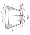
- a mixer apparatus is generally designated by the reference number 10.
- the mixer 10 includes a floor 12 which is attached to an undercarriage 14.
- the floor 12 may either be parallel to the ground or at an angle thereto.
- the undercarriage 14 can be mounted in a stationary position or on a truck chassis, but is most often mounted on a set of wheels 16 with a hitch 18 for towing the mixer apparatus.
- a wall 20 is attached to the floor 12, and extends upward from the floor 12 to form an enclosure 22 for the reception of feed through the top opening 24.
- the wall 20 includes a first end 26, a second end 28, a first side 30 and a second side 32.
- the wall 20 also has a bottom edge 34 adjacent to the floor 12, and a top edge 36 adjacent to the top opening 24.
- a discharge opening 38 is located adjacent to the bottom edge 34 of the wall 20 for discharge of feed materials after mixing.
- a door 40 is movably positioned adjacent to the discharge opening 38 so that the discharge opening can be closed while mixing and opened for discharging feed materials.
- the auger 42 is positioned inside the enclosure 22 adjacent to the floor 12.
- the auger 42 includes a lower core 44 with an axis of rotation 46 extending approximately perpendicular through the floor 12.
- the lower core 44 is shown at substantial length to house a gearbox (not shown), however the lower core could also be very short in length, consisting essentially of the gearbox output shaft.
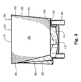
- the auger 42 also includes an upper core 48 which is adjacent and above the lower core 44.
- the upper core 48 has a centerline 50 which is located longitudinally through the center of the upper core 48.
- the auger 42 can be rotated around the axis of rotation 46 in the direction of rotation 52 with a tractor vehicle by means of transmission shafts and gear wheels (not shown) located under the floor 12.
- the auger 42 also includes a lower flighting segment 54 attached to the lower core 44 in a spiral configuration.
- the lower flighting segment 54 has a leading edge 56 adjacent to the floor 12, a trailing edge 58 at the opposite end of the lower flighting segment 54, an inner edge 60 adjacent and attached to the lower core 44, and an outer edge 62 adjacent to the wall 20 of the enclosure 22.
- the auger 42 also includes an upper flighting segment 64 attached to the upper core 48.
- the upper flighting segment 64 has a further leading edge 66 adjacent to the trailing edge 58 of the lower flighting segment 54, a further trailing edge 68 at the opposite end of the upper flighting segment 64, a further inner edge 70 adjacent and attached to the upper core 48, and a further outer edge 72 adjacent to the wall 20 of the enclosure 22.
- the lower flighting segment 54 is typically larger in diameter than the upper flighting segment 64, so that the overall shape of the auger 42 is conical, being wider at the bottom edge 34 of the of the wall 20 and narrower toward the top edge 36 of the wall 20.
- the lower flighting segment 54 may also include a paddle 74 which assists in feed movement.
- the upper flighting segment 64 and lower flighting segment 54 include a plurality of knives 78 which cooperate with the wall 20 to cut and process the feed material.
- the knives 78 include a cutting edge 80 which is generally positioned forward in the direction of rotation 52 of the auger 42, and a dull edge 82 which is generally positioned rearward in the direction of rotation 52 of the auger 42.
- the knives 78 also include an inner side 84 which is adjacent to the lower flighting segment 54 or upper flighting segment 64, and an outer side 86 which is closest to the wall 20 of the enclosure 22.
- the centerline 50 of the upper core 48 is angled from the axis of rotation 46 of the lower core 44.
- the top of the upper core 48 will travel in a circular path 88 inside the enclosure 22.
- the upper flighting segment 64 attached to the upper core 48 and the knives 78 attached to the upper flighting segment 64 also follow the circular path 88.
- the circular path 88 resulting from the angled centerline 50 of the upper core 48 allows the auger 42 and the upper flighting segment 64 to contact a much greater volume of the feed materials F than if the upper core 48 were aligned with the axis of rotation 46.
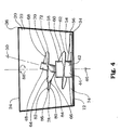
- the centerline 50 of the upper core 48 is parallel and spaced offset to the axis of rotation 46 of the lower core 44.
- the top of the upper core 48 will travel in a circular path 88 inside the enclosure 22.
- the upper flighting segment 64 attached to the upper core 48 and the knives 78 attached to the upper flighting segment 64 also follow the circular path 88.
- the circular path 88 resulting from the offset centerline 50 of the upper core 48 allows the auger 42 and the upper flighting segment 64 to contact a much greater volume of the feed materials F than if the centerline 50 of the upper core 48 were concentric with the axis of rotation 46.
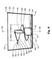
- a single core is used that includes an axis of rotation 46.
- a first flighting segment 64 includes one or more lobes 90 which extend to at least one side of the first flighting segment 64.
- the lobes 90 cause the first flighting segment 64 to be non-symmetrical to the centerline 50 of the upper core 48. That is, the maximum extent (ME1) of a first portion of the first flighting segment 64 is substantially smaller than a maximum extent (ME2) of a second portion of the first flighting segment 64 that is substantially opposite the first portion.
- substantially smaller is intended to mean that ME1 and ME2 have a difference of greater than 25%, preferably the difference between ME1 and ME2 is in the range of 25% to 75%.
- a maximum extent of the flighting can be non-monotonic such that, as the maximum extent is viewed along an increasing height, the maximum extent increase and decreases, as opposed to known augers having flights with constant maximum extent or a strictly decreasing maximum extent with increasing height along the auger.
- the knives 78 are attached to the lobes 90 at the inner side 84. As the auger 42 rotates in the direction of rotation 52 around the axis of rotation 46, the lobes 90 and knives 78 contact a greater volume of the feed materials F than if the lobes 90 were not present.
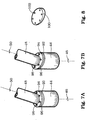
- the lower core 44 and upper core 48 are attached by a pair of matching plates including a lower core mounting plate 92 and an upper core mounting plate 94.
- the core mounting plates 92 and 94 have a plurality of matching fastening holes 96 and are attached by a plurality of fasteners 98.
- the upper core mounting plate 94 can be rotated and fastened to the lower core mounting plate 92 in several combinations of the matching fastening holes 96 to allow the upper core 48 to tilt in several different directions relative to the lower core 44.
- the lower core mounting plate 92 in Fig. 7 is shown in a plane perpendicular to the axis of rotation 46.
- the lower core mounting plate 92 in Fig. 7A is shown mounted at an angle to the axis of rotation 46 to allow a further range of angular adjustment of the upper core mounting plate 94 and thus the upper core 48.
- a core mounting plate shim 100 is shown, with further fastening holes 102 which match the fastening holes 96 in the lower and upper core mounting plates 92 and 94 as shown in Figs. 7A and 7B.
- the core mounting plate shim 100 when inserted between the lower and upper core mounting plates 92 and 94 allows a further range of angular adjustment of the upper core mounting plate 94 and thus the upper core 48.
- feed materials (F) such as hay, forages, and grains are loaded into the mixer through the top opening (24). Often these materials include long stemmed hay, either in square or round bales.
- the mixer is typically powered by a tractor (not shown), which rotates the auger (42) inside the mixer.
- the auger 42 is arranged so that when the auger 42 is rotated around the axis of rotation 46 in the direction of rotation 52, the lower flighting segment 54 sweeps the feed materials (F) from the floor 12 upwards toward the upper flighting segment 64. When the feed material (F) reaches the top of the upper flighting segment 64, it begins to fall back into the enclosure 20 for further mixing.
- the feed material (F) is also carried in a circular motion around the perimeter of the enclosure 22 due to the rotary movement of the auger 42 around the axis of rotation 46 in the direction of rotation 52.
- the upper core 48 is not concentric with the axis of rotation 46, so the upper flighting segment 64 is closer to the perimeter of the enclosure 22 during at least one portion of the auger rotation.
- the knives 78 can more efficiently cut and process the feed materials (F).
- the door 40 is opened and the feed material (F) is discharged out of the mixer 10 for distribution to the intended livestock.
- Alternative mixing apparatus configurations often includes two or more augers inside the enclosure, which function in similar fashion to the operation described herein.
Landscapes
- Life Sciences & Earth Sciences (AREA)
- Chemical & Material Sciences (AREA)
- Chemical Kinetics & Catalysis (AREA)
- Environmental Sciences (AREA)
- Birds (AREA)
- Animal Husbandry (AREA)
- Biodiversity & Conservation Biology (AREA)
- Mixers Of The Rotary Stirring Type (AREA)
- Feeding And Watering For Cattle Raising And Animal Husbandry (AREA)
- Accessories For Mixers (AREA)
Applications Claiming Priority (2)
| Application Number | Priority Date | Filing Date | Title |
|---|---|---|---|
| US10/767,350 US7040801B2 (en) | 2004-01-30 | 2004-01-30 | Mixing apparatus with non-concentric auger |
| US767350 | 2004-01-30 |
Publications (2)
| Publication Number | Publication Date |
|---|---|
| EP1559474A2 true EP1559474A2 (fr) | 2005-08-03 |
| EP1559474A3 EP1559474A3 (fr) | 2005-12-28 |
Family
ID=34654345
Family Applications (1)
| Application Number | Title | Priority Date | Filing Date |
|---|---|---|---|
| EP05100326A Withdrawn EP1559474A3 (fr) | 2004-01-30 | 2005-01-20 | Mélangeuse avec une vis non concentrique |
Country Status (2)
| Country | Link |
|---|---|
| US (1) | US7040801B2 (fr) |
| EP (1) | EP1559474A3 (fr) |
Cited By (1)
| Publication number | Priority date | Publication date | Assignee | Title |
|---|---|---|---|---|
| DE202011003695U1 (de) * | 2011-03-09 | 2012-03-01 | Mayer Verwaltungs Gmbh & Co. Kg | Mischschnecke für Futtermischwagen |
Families Citing this family (10)
| Publication number | Priority date | Publication date | Assignee | Title |
|---|---|---|---|---|
| ES2314211T3 (es) * | 2002-06-04 | 2009-03-16 | Kuhn North America, Inc. | Mezcaldora vertical para un dispositivo mezclador de forraje. |
| DE20308404U1 (de) * | 2003-05-28 | 2004-09-30 | Trioliet Mullos B.V. | Mischer |
| US7040801B2 (en) * | 2004-01-30 | 2006-05-09 | Kuhn Knight Inc. | Mixing apparatus with non-concentric auger |
| US7347616B2 (en) * | 2006-05-26 | 2008-03-25 | Kuhn North America, Inc. | Swept kickers for vertical mixer augers |
| US20090052276A1 (en) * | 2007-08-25 | 2009-02-26 | Grieb Edward J | Agitator |
| US20090080285A1 (en) * | 2007-09-26 | 2009-03-26 | Proteus Design, Inc. | Processor |
| SE536485C2 (sv) * | 2012-04-02 | 2013-12-17 | Sorubin Ab | Flödesskapande anordning innefattande impeller och slitskiva |
| NL2008677C2 (nl) * | 2012-04-20 | 2013-10-23 | Lely Patent Nv | Voermengwagen. |
| USD869789S1 (en) * | 2017-04-19 | 2019-12-10 | Rotecna, S.A. | Machine for processing animal feed |
| US12058963B1 (en) * | 2023-04-21 | 2024-08-13 | Gahler Innovations LLC | Devices and methods for reducing grain bin entrapment and grain bin spoilage |
Family Cites Families (14)
| Publication number | Priority date | Publication date | Assignee | Title |
|---|---|---|---|---|
| US2830695A (en) * | 1955-12-16 | 1958-04-15 | Marion H Fennimore | Flexible screw conveyor |
| US3252562A (en) * | 1963-10-07 | 1966-05-24 | Brock Mfg Inc | Feed distributing apparatus |
| US3251467A (en) * | 1964-01-03 | 1966-05-17 | Elmer L Bakke | Attachment for grain auger |
| US3580384A (en) * | 1969-01-27 | 1971-05-25 | Ameron Inc | Material feeding apparatus |
| US3721333A (en) * | 1971-06-09 | 1973-03-20 | Allis Chalmers | Combine grain bin unloader |
| US4989716A (en) * | 1990-06-11 | 1991-02-05 | Gerald Stuckey | Adjustable angle auger |
| US5129502A (en) * | 1991-03-04 | 1992-07-14 | Coaltex, Inc. | Helical snake |
| US5119931A (en) * | 1991-05-13 | 1992-06-09 | Alloway Manufacturing | Flexible joint for augers |
| US5230419A (en) * | 1992-03-25 | 1993-07-27 | Spar Aerospace Limited | Remotely positionable material extraction device |
| US5305586A (en) * | 1992-08-20 | 1994-04-26 | Lundahl Research, Inc. | Crop processor |
| NL1006170C2 (nl) * | 1997-05-30 | 1998-12-01 | Trioliet Mullos | Werkwijze en inrichting voor het mengen van voer. |
| ITPD20010229A1 (it) * | 2001-09-28 | 2003-03-28 | Tiziano Faccia | Carro perfezionato per la trinciatura e la miscelazione di prodotti d'uso zootecnico. |
| DE20315988U1 (de) * | 2003-10-17 | 2003-12-11 | B. Strautmann & Söhne GmbH u. Co | Vertikale Mischschnecke eines Futtermischwagens |
| US7040801B2 (en) * | 2004-01-30 | 2006-05-09 | Kuhn Knight Inc. | Mixing apparatus with non-concentric auger |
-
2004
- 2004-01-30 US US10/767,350 patent/US7040801B2/en not_active Expired - Lifetime
-
2005
- 2005-01-20 EP EP05100326A patent/EP1559474A3/fr not_active Withdrawn
Non-Patent Citations (1)
| Title |
|---|
| None * |
Cited By (2)
| Publication number | Priority date | Publication date | Assignee | Title |
|---|---|---|---|---|
| DE202011003695U1 (de) * | 2011-03-09 | 2012-03-01 | Mayer Verwaltungs Gmbh & Co. Kg | Mischschnecke für Futtermischwagen |
| EP2497359A3 (fr) * | 2011-03-09 | 2014-07-09 | Mayer Verwaltungs GmbH & Co. KG | Vis mélangeur pour chariot mélangeur de fourrage |
Also Published As
| Publication number | Publication date |
|---|---|
| US7040801B2 (en) | 2006-05-09 |
| US20050169103A1 (en) | 2005-08-04 |
| EP1559474A3 (fr) | 2005-12-28 |
Similar Documents
| Publication | Publication Date | Title |
|---|---|---|
| US7347616B2 (en) | Swept kickers for vertical mixer augers | |
| US7004617B2 (en) | Mixer with dissimilar augers | |
| CA2190318C (fr) | Malaxeur d'aliments comportant une vis conique sans fin | |
| US5647665A (en) | Vertical feed mixer with flighting plows | |
| US20110121114A1 (en) | Material mixer with multi-flighted auger | |
| US5622323A (en) | Hay processing system for a mixer feeder | |
| US6328465B1 (en) | Vertical feed mixer with auger having center post with sloped top | |
| US4896970A (en) | Feed mixer | |
| US6863433B2 (en) | Auger with forward angled leading edge | |
| US7040801B2 (en) | Mixing apparatus with non-concentric auger | |
| US6923393B1 (en) | Horizontal feed mixer and method for using same | |
| AU2013255453B2 (en) | An animal feed mixing and dispensing apparatus | |
| US6409376B1 (en) | Mixer apparatus | |
| CA1057281A (fr) | Melangeur d'aliments (betail) a vis conique dotee d'un tube d'aspiration | |
| US7165880B2 (en) | Mixing apparatus with non-symmetrical sides | |
| US3415492A (en) | Feed mixer | |
| KR20010070822A (ko) | 사료 배합 장치 | |
| US20040136264A1 (en) | Mixer apparatus | |
| CA2486269C (fr) | Tariere dotee d'un bord incline vers l'avant | |
| US7281843B1 (en) | Vertical agricultural mixer | |
| KR200246160Y1 (ko) | 사료 배합 장치 | |
| JPH05219927A (ja) | 飼料の混合装置及び混合飼料の製造方法 | |
| EP0937378A2 (fr) | Epandeur de fumier | |
| IES84111Y1 (en) | An auger | |
| IE20050353A1 (en) | An auger |
Legal Events
| Date | Code | Title | Description |
|---|---|---|---|
| PUAI | Public reference made under article 153(3) epc to a published international application that has entered the european phase |
Free format text: ORIGINAL CODE: 0009012 |
|
| AK | Designated contracting states |
Kind code of ref document: A2 Designated state(s): AT BE BG CH CY CZ DE DK EE ES FI FR GB GR HU IE IS IT LI LT LU MC NL PL PT RO SE SI SK TR |
|
| AX | Request for extension of the european patent |
Extension state: AL BA HR LV MK YU |
|
| PUAL | Search report despatched |
Free format text: ORIGINAL CODE: 0009013 |
|
| AK | Designated contracting states |
Kind code of ref document: A3 Designated state(s): AT BE BG CH CY CZ DE DK EE ES FI FR GB GR HU IE IS IT LI LT LU MC NL PL PT RO SE SI SK TR |
|
| AX | Request for extension of the european patent |
Extension state: AL BA HR LV MK YU |
|
| 17P | Request for examination filed |
Effective date: 20060628 |
|
| AKX | Designation fees paid |
Designated state(s): AT BE BG CH CY CZ DE DK EE ES FI FR GB GR HU IE IS IT LI LT LU MC NL PL PT RO SE SI SK TR |
|
| 17Q | First examination report despatched |
Effective date: 20061128 |
|
| STAA | Information on the status of an ep patent application or granted ep patent |
Free format text: STATUS: THE APPLICATION IS DEEMED TO BE WITHDRAWN |
|
| 18D | Application deemed to be withdrawn |
Effective date: 20070411 |