EP1559325B1 - Brine container with filtering device - Google Patents
Brine container with filtering device Download PDFInfo
- Publication number
- EP1559325B1 EP1559325B1 EP05000371A EP05000371A EP1559325B1 EP 1559325 B1 EP1559325 B1 EP 1559325B1 EP 05000371 A EP05000371 A EP 05000371A EP 05000371 A EP05000371 A EP 05000371A EP 1559325 B1 EP1559325 B1 EP 1559325B1
- Authority
- EP
- European Patent Office
- Prior art keywords
- filter
- brine
- suction
- region
- filters
- Prior art date
- Legal status (The legal status is an assumption and is not a legal conclusion. Google has not performed a legal analysis and makes no representation as to the accuracy of the status listed.)
- Not-in-force
Links
Images
Classifications
-
- A—HUMAN NECESSITIES
- A23—FOODS OR FOODSTUFFS; TREATMENT THEREOF, NOT COVERED BY OTHER CLASSES
- A23B—PRESERVING, e.g. BY CANNING, MEAT, FISH, EGGS, FRUIT, VEGETABLES, EDIBLE SEEDS; CHEMICAL RIPENING OF FRUIT OR VEGETABLES; THE PRESERVED, RIPENED, OR CANNED PRODUCTS
- A23B4/00—General methods for preserving meat, sausages, fish or fish products
- A23B4/02—Preserving by means of inorganic salts
-
- A—HUMAN NECESSITIES
- A23—FOODS OR FOODSTUFFS; TREATMENT THEREOF, NOT COVERED BY OTHER CLASSES
- A23B—PRESERVING, e.g. BY CANNING, MEAT, FISH, EGGS, FRUIT, VEGETABLES, EDIBLE SEEDS; CHEMICAL RIPENING OF FRUIT OR VEGETABLES; THE PRESERVED, RIPENED, OR CANNED PRODUCTS
- A23B4/00—General methods for preserving meat, sausages, fish or fish products
- A23B4/26—Apparatus for preserving using liquids ; Methods therefor
- A23B4/28—Apparatus for preserving using liquids ; Methods therefor by injection of liquids
- A23B4/285—Apparatus for preserving using liquids ; Methods therefor by injection of liquids with inorganic salts
-
- Y—GENERAL TAGGING OF NEW TECHNOLOGICAL DEVELOPMENTS; GENERAL TAGGING OF CROSS-SECTIONAL TECHNOLOGIES SPANNING OVER SEVERAL SECTIONS OF THE IPC; TECHNICAL SUBJECTS COVERED BY FORMER USPC CROSS-REFERENCE ART COLLECTIONS [XRACs] AND DIGESTS
- Y02—TECHNOLOGIES OR APPLICATIONS FOR MITIGATION OR ADAPTATION AGAINST CLIMATE CHANGE
- Y02A—TECHNOLOGIES FOR ADAPTATION TO CLIMATE CHANGE
- Y02A40/00—Adaptation technologies in agriculture, forestry, livestock or agroalimentary production
- Y02A40/90—Adaptation technologies in agriculture, forestry, livestock or agroalimentary production in food processing or handling, e.g. food conservation
Definitions
- the invention relates to a brine container, on which a suction filter is arranged.
- It may, for example, be a brine container for pickle, which is pumped through the suction filter and fed to a pickling machine.
- pickle pellets flowing away from the pickling machine are returned to the brine tank via a coarse filter.
- the suction filter serves to protect the brine pump and to prevent clogging of injection needles of the pickling machine by introduced particles or impurities.
- the suction filter is clogged over time by the particles it has filtered out of the pickle and can, for example, be removed by hand for cleaning.
- GB 1 525 968 describes a plant for purifying brine, in which polluted returning brine is taken from a collection tank through a filter head, treated by ultraviolet irradiation and fed to a second tank, from which it is withdrawn via another filter and supplied to injection needles.
- JP 08 000 239 describes a plant for the sterilization and disinfection of food by means of a sterilizing liquid.
- the liquid is pumped out of a sterilization tank and pumped back through a recycling plant with filters to outlet openings in the tank.
- Out SU 568429 A (WPI database XP-002323513) a circulating filter system for brine for the fish industry is known. A continuous process is ensured by providing an overflow in a filter container above the filters.
- the object of the invention is to provide a brine container of the type mentioned, in which the intake filter is permanently and reliably relieved.
- the brine can thus be constantly pumped through the recirculation filter system and thereby filtered. In this way impurities are discharged from the brine. Due to the circulation filter system can therefore effectively and to a large extent dirt particles are removed from the cycle of brine, so that the intake filter is relieved and polluted only much slower.
- a change of the filter element can continue to be removed from the lake brine tank via the suction filter, so that, for example, a pickling machine can operate in continuous operation. This is particularly advantageous since the filter element can be changed or removed and cleaned without interruption during production.
- the brine container has a return area and one of which is separated by the separation filter suction area, wherein the suction filter is arranged in the suction area and the brine pumpable with the pump of the circulation filter system from the return area into the intake area.
- a particular advantage is that the intake area is supplied with brine, which has been filtered by the filter system. This results in the intake of the brine container a lower degree of contamination than in the return region of the brine container. Due to the lower degree of contamination of the intake filter is significantly relieved and dirty at best still very slowly.
- To replace the filter element is preferably the inlet to the filter shut off, so that the filter or the filter element can be removed without unfiltered brine is pumped into the intake. Alternatively, the pump could be switched off to replace the filter element. It is advantageous in both cases that when changing the filter element no unfiltered brine gets into the intake area.
- the suction filter can be relieved even more effectively in continuous operation.
- the return area and the suction area are connected by the separation filter.
- the separating filter may be, for example, a sheet with slots or other openings.
- the separation filter allows a Laketransfer between the return area and the suction of the brine tank and thus causes a leveling in the two areas. Since, depending on the performance of the pump of the filter system hardly brine flows through the separation filter or the brine flows back substantially from the intake into the return area, the separation filter hardly pollutes. Some flow in the brine tank caused by the pump of the filter system is beneficial to keep the brine moving so that less solids settle to the bottom.
- the filter system has at least two filters whose inlet sides can be shut off by means of a switching device.
- the switching device for example, the inlet of a filter can be blocked, the filter element is to be replaced. It is also conceivable to operate with the switching device one filter at a time until it is to be replaced, and then only to switch to the other filter.
- the filter system may preferably be additionally shut off the outlet sides of the filter.
- the filter system has a pressure measuring device for differential pressure measurement in front of and behind the filter.
- a pressure measuring device for differential pressure can be connected, for example, to a monitoring device for the differential pressure, which outputs a signal when a limit value is exceeded.
- a display can be made, which indicates the necessary change of the filter. This eliminates the need for optical control of the filters.
- the single figure shows a brine tank with a filter system.
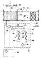
- the FIGURE shows a brine container with a return region 10 and a suction region 12, which are separated from one another by a separation filter 14 inserted into the brine container.
- the separating filter 14 has in its upper region a wall 16 with which it projects beyond the liquid surface 18.
- the brine container belongs, for example, to a salting machine, which is supplied by means of a pump via a suction line 20 with pickle 22, which is sucked in via a suction filter 24.
- the suction filter 24 effects finer filtering than the separation filter 14.
- Lake flowing away from the pickling machine is returned to the return area 10 via a coarse filter 26.
- the lake located in the return area 10 still has a certain degree of contamination after coarse filtration.
- the return region 10 and the intake region 12 are connected by a symbolically represented recirculation filter system 28, which will be explained in more detail below.
- the filter system 28 has a pump 30, which is connected in each case via valves 32 to the filter 34.
- the filtered by the filters 34 brine is fed via a line 36 into the intake region 12.
- the filters 34 are each, for example, interchangeable filter cartridges, which are flowed through by the brine from the inside to the outside and cause fine filtering of the brine. Contaminants contained in the lake accumulate inside of filter cartridges 38 of the filter. A full filter can be removed from the filter system after closing the corresponding valve 32 and cleaned or replaced with a new filter. Depending on the type of brine different filter cartridges 38 can be used. Optionally, only the filter inserts 38 can be removed.
- valves 32 are, for example, interconnected so that they form a switching device which opens the inlet to one of the two filters 34. In this way, a filter 34 can be used until it is full. The respective other filter 34 is then ready for use, so that a full filter cartridge 38 can be removed during operation and cleaned.
- a pressure measuring device 40 In front of and behind the filters, a pressure measuring device 40 is arranged in each case.
- the pressure measuring devices 40 are connected to a monitoring device 42, which monitors the differential pressure in front of and behind the filters. If a limit value is exceeded, as may occur, for example, in the case of a full filter 34, the monitoring device 42 outputs an optical and / or acoustic signal.
- the pressure measuring devices 40 or the monitoring device 42 may also be connected to an indication of the degree of contamination.
- the filter system 28 can be mounted, for example, as an assembly next to the brine tank.
- the filters 34 are arranged standing next to the basin of the brine container.
- the filter cartridges 38 can be removed upwardly from the filter 34 through corresponding openings. These openings are above the liquid surface 18, so that no brine 22 expires from the intake 12. However, the filters 34 are arranged so that upon removal of a filter cartridge 38 accidental contamination of the tank of Lake container is avoided.
- the filters 34 may be arranged horizontally, and they may also be located entirely below the liquid surface 18, but outside the basin of the brine container.
- further valves 44 are provided on the downstream side of the filters 34 to prevent leakage of the brine 22 when changing a filter. These valves 44 are shown in dashed lines in Figure 4.
- a differential pressure measuring device can be provided which directly measures the difference of the pressure in front of and behind the filters 34. It is in turn connected to the monitoring device 42, which outputs an optical and / or acoustic signal when a limit value is exceeded. In this example, it also outputs a signal with which an automatic switching of the filter 34 via the valves 32 is effected when a limit value is exceeded.
- a changeover valve is provided, via which, depending on the setting of the changeover valve, the inlet side of one or the other filter 34 is connected to the pump 30.
- the valves 44 may be connected or replaced by a switching valve.
- the pump may optionally be arranged in the line 36.
Abstract
Description
Die Erfindung betrifft einen Lakebehälter, an dem ein Ansaugfilter angeordnet ist.The invention relates to a brine container, on which a suction filter is arranged.
Es kann sich beispielsweise um einen Lakebehälter für Pökellake handeln, die durch den Ansaugfilter abgepumpt und einer Pökelmaschine zugeführt wird. Üblicherweise wird von der Pökelmaschine abfließende Pökellake über einen Grobfilter in den Lakebehälter zurückgeführt. Der Ansaugfilter dient dazu, die Lakepumpe zu schützen und ein Verstopfen von Injektionsnadeln der Pökelmaschine durch eingebrachte Partikel oder Verunreinigungen zu verhindern. Der Ansaugfilter wird durch die von ihm aus der Pökellake gefilterten Partikel mit der Zeit verstopft und kann beispielsweise von Hand zur Reinigung entnommen werden.It may, for example, be a brine container for pickle, which is pumped through the suction filter and fed to a pickling machine. Usually, pickle pellets flowing away from the pickling machine are returned to the brine tank via a coarse filter. The suction filter serves to protect the brine pump and to prevent clogging of injection needles of the pickling machine by introduced particles or impurities. The suction filter is clogged over time by the particles it has filtered out of the pickle and can, for example, be removed by hand for cleaning.
Es ist bekannt, zwischen dem Grobfilter und dem Ansaugfilter im Lakebehälter zusätzliche Filter vorzusehen, um ein schnelles Verstopfen des Ansaugfilters zu vermeiden. Üblicherweise wird dazu ein Schiebefilter von oben in den Lakebehälter eingeschoben, so daß dieser in zwei Bereiche mit unterschiedlichem Verschmutzungsgrad der Lake unterteilt wird. Der Schiebefilter verschmutzt allmählich und muß regelmäßig zur Reinigung entnommen werden. Auch bei der Verwendung mehrerer solcher Schiebefilter kann beim Entfernen eines Filters zur Reinigung Lake mit höherem Verschmutzungsgrad in einen Bereich von Lake mit geringerem Verschmutzungsgrad eingebracht werden.It is known to provide additional filters between the coarse filter and the suction filter in the brine tank in order to avoid a rapid clogging of the suction filter. Usually, a sliding filter is inserted from above into the brine tank, so that it is divided into two areas with different degree of contamination of the brine. The sliding filter gradually becomes dirty and must be removed regularly for cleaning. Even with the use of a plurality of such sliding filters, when removing a filter for cleaning, brine with a higher degree of soiling may be introduced into a less polluted area of brine.
Aus
Aufgabe der Erfindung ist es, einen Lakebehälter der eingangs genannten Art zu schaffen, bei dem der Ansaugfilter dauerhaft und zuverlässig entlastet wird.The object of the invention is to provide a brine container of the type mentioned, in which the intake filter is permanently and reliably relieved.
Diese Aufgabe wird erfindungsgemäß durch einen Lakebehälter nach Anspruch 1 gelöst.This object is achieved by a brine container according to claim 1.
Die Lake kann so ständig durch das Umwälz-Filtersystem gepumpt und dabei gefiltert werden. Auf diese Weise werden Verunreinigungen aus der Lake ausgetragen. Durch das Umwälz-Filtersystem können daher wirkungsvoll und in großem Ausmaß Schmutzpartikel dem Kreislauf der Lake entnommen werden, so daß der Ansaugfilter entlastet ist und nur noch deutlich langsamer verschmutzt. Während eines Wechsels des Filterelements kann weiterhin Lake aus dem Lakebehälter über den Ansaugfilter entnommen werden, so daß beispielsweise eine Pökelmaschine im Dauerbetrieb arbeiten kann. Dies ist besonders vorteilhaft, da so ohne eine Unterbrechung während der Produktion das Filterelement gewechselt oder entnommen und gereinigt werden kann.The brine can thus be constantly pumped through the recirculation filter system and thereby filtered. In this way impurities are discharged from the brine. Due to the circulation filter system can therefore effectively and to a large extent dirt particles are removed from the cycle of brine, so that the intake filter is relieved and polluted only much slower. During a change of the filter element can continue to be removed from the lake brine tank via the suction filter, so that, for example, a pickling machine can operate in continuous operation. This is particularly advantageous since the filter element can be changed or removed and cleaned without interruption during production.
Der Lakebehälter weist einen Rücklaufbereich und einen davon durch den Trennfilter getrennten Ansaugbereich auf, wobei der Ansaugfilter im Ansaugbereich angeordnet ist und die Lake mit der Pumpe des Umwälz-Filtersystems von dem Rücklaufbereich in den Ansaugbereich pumpbar ist. Ein besonderer Vorteil ist dabei, daß der Ansaugbereich mit Lake versorgt wird, die durch das Filtersystem gefiltert wurde. Dadurch ergibt sich im Ansaugbereich des Lakebehälters ein geringerer Verschmutzungsgrad als im Rücklaufbereich des Lakebehälters. Aufgrund des geringeren Verschmutzungsgrades ist der Ansaugfilter deutlich entlastet und verschmutzt allenfalls noch sehr langsam. Zum Auswechseln des Filterelements ist bevorzugt der Zulauf zum Filter absperrbar, so daß der Filter oder das Filterelement entnommen werden kann, ohne daß ungefilterte Lake in den Ansaugbereich gepumpt wird. Alternativ könnte zum Auswechseln des Filterelements auch die Pumpe abschaltbar sein. Vorteilhaft ist in beiden Fällen, daß bei einem Wechsel des Filterelements keine ungefilterte Lake in den Ansaugbereich gelangt. Der Ansaugfilter kann so im Dauerbetrieb noch wirksamer entlastet werden.The brine container has a return area and one of which is separated by the separation filter suction area, wherein the suction filter is arranged in the suction area and the brine pumpable with the pump of the circulation filter system from the return area into the intake area. A particular advantage is that the intake area is supplied with brine, which has been filtered by the filter system. This results in the intake of the brine container a lower degree of contamination than in the return region of the brine container. Due to the lower degree of contamination of the intake filter is significantly relieved and dirty at best still very slowly. To replace the filter element is preferably the inlet to the filter shut off, so that the filter or the filter element can be removed without unfiltered brine is pumped into the intake. Alternatively, the pump could be switched off to replace the filter element. It is advantageous in both cases that when changing the filter element no unfiltered brine gets into the intake area. The suction filter can be relieved even more effectively in continuous operation.
Der Rücklaufbereich und der Ansaugbereich sind durch den Trennfilter verbunden. Bei dem Trennfilter kann es sich beispielsweise um ein Blech mit Schlitzen oder anderen Öffnungen handeln. Der Trennfilter läßt einen Laketransfer zwischen dem Rücklaufbereich und dem Ansaugbereich des Lakebehälters zu und bewirkt so einen Niveauausgleich in den beiden Bereichen. Da je nach Leistung der Pumpe des Filtersystems kaum Lake durch den Trennfilter strömt oder die Lake im wesentlichen vom Ansaugbereich in den Rücklaufbereich zurückströmt, verschmutzt der Trennfilter kaum. Eine gewisse, von der Pumpe des Filtersystems verursachte Strömung im Lakebehälter ist vorteilhaft, um die Lake in Bewegung zu halten, so daß sich weniger Feststoffe am Boden absetzen.The return area and the suction area are connected by the separation filter. The separating filter may be, for example, a sheet with slots or other openings. The separation filter allows a Laketransfer between the return area and the suction of the brine tank and thus causes a leveling in the two areas. Since, depending on the performance of the pump of the filter system hardly brine flows through the separation filter or the brine flows back substantially from the intake into the return area, the separation filter hardly pollutes. Some flow in the brine tank caused by the pump of the filter system is beneficial to keep the brine moving so that less solids settle to the bottom.
Vorteilhafte Ausgestaltungen der Erfindung ergeben sich aus den Unteransprüchen.Advantageous embodiments of the invention will become apparent from the dependent claims.
In einer bevorzugten Ausführungsform weist das Filtersystem mindestens zwei Filter auf, deren Zulaufseiten mittels einer Umschalteinrichtung absperrbar sind. In diesem Fall kann mittels der Umschalteinrichtung beispielsweise der Zulauf eines Filters gesperrt werden, dessen Filterelement ausgewechselt werden soll. Es ist auch denkbar, mit der Umschalteinrichtung jeweils einen Filter solange zu betreiben, bis er gewechselt werden soll, und dann erst auf den anderen Filter umzuschalten. Je nach Anordnung und Aufbau des Filtersystems können vorzugsweise zusätzlich die Ablaufseiten der Filter absperrbar sein.In a preferred embodiment, the filter system has at least two filters whose inlet sides can be shut off by means of a switching device. In this case, by means of the switching device, for example, the inlet of a filter can be blocked, the filter element is to be replaced. It is also conceivable to operate with the switching device one filter at a time until it is to be replaced, and then only to switch to the other filter. Depending on the arrangement and structure of the filter system may preferably be additionally shut off the outlet sides of the filter.
Vorzugsweise weist das Filtersystem eine Druckmeßeinrichtung zur Differenzdruckmessung vor und hinter dem Filter auf. Diese kann beispielsweise an eine Überwachungseinrichtung für den Differenzdruck angeschlossen sein, welche beim Überschreiten eines Grenzwertes ein Signal ausgibt. Wird beispielsweise der Differenzdruck aufgrund der Verschmutzung des Filters zu groß, so kann eine Anzeige erfolgen, die auf den nötigen Wechsel des Filters hinweist. Dadurch entfällt die Notwendigkeit einer optischen Kontrolle der Filter.Preferably, the filter system has a pressure measuring device for differential pressure measurement in front of and behind the filter. This can be connected, for example, to a monitoring device for the differential pressure, which outputs a signal when a limit value is exceeded. For example, if the differential pressure due to the contamination of the filter is too large, then a display can be made, which indicates the necessary change of the filter. This eliminates the need for optical control of the filters.
Bei mehreren Filtern, die über die Umschalteinrichtung umschaltbar sind, kann beim Überschreiten eines Grenzwertes des Differenzdrucks auch eine automatische Umschaltung des durchströmten Filters erfolgen. Auf diese Weise kann bei einem vollen Filter automatisch auf den nächsten Filter umgeschaltet werden, so daß dieser verwendet wird und der volle Filter währenddessen ausgewechselt werden kann.In the case of several filters which can be switched over via the switching device, when the limit value of the differential pressure is exceeded, an automatic switching of the filter through which the fluid flows can also take place. In this way, with a full filter can be automatically switched to the next filter so that it is used and the full filter can be replaced while.
Anstelle der Messung des Differenzdrucks vor und hinter dem Filter oder zusätzlich kann auch eine Messung der Leistungsaufnahme der Pumpe des Filtersystems erfolgen.Instead of measuring the differential pressure in front of and behind the filter or in addition, it is also possible to measure the power consumption of the pump of the filter system.
Im folgenden werden Ausführungsbeispiele der Erfindung anhand der Zeichnung näher erläutert.In the following, embodiments of the invention will be explained in more detail with reference to the drawing.
Die einzige Figur zeigt einen Lakebehälter mit einem Filtersystem.The single figure shows a brine tank with a filter system.
Die Figur zeigt einen Lakebehälter mit einem Rücklaufbereich 10 und einem Ansaugbereich 12, die durch einen in den Lakebehälter eingesetzten Trennfilter 14 voneinander getrennt sind. Der Trennfilter 14 weist in seinem oberen Bereich eine Wand 16 auf, mit der er über die Flüssigkeitsoberfläche 18 hinausragt. Der Lakebehälter gehört beispielsweise zu einer Pökelmaschine, die mittels einer Pumpe über eine Ansaugleitung 20 mit Pökellake 22, die über einen Ansaugfilter 24 angesaugt wird, versorgt wird. Der Ansaugfilter 24 bewirkt beispielsweise eine feinere Filterung als der Trennfilter 14.The FIGURE shows a brine container with a
Von der Pökelmaschine abfließende Lake wird über einen Grobfilter 26 in den Rücklaufbereich 10 zurückgeführt. Die sich im Rücklaufbereich 10 befindende Lake weist nach der Grobfilterung immer noch einen gewissen Verschmutzungsgrad auf. Der Rücklaufbereich 10 und der Ansaugbereich 12 sind durch ein symbolisch dargestelltes Umwälz-Filtersystem 28 verbunden, das im folgenden näher erläutert wird.Lake flowing away from the pickling machine is returned to the
Das Filtersystem 28 weist eine Pumpe 30 auf, die jeweils über Ventile 32 an Filter 34 angeschlossen ist. Die von den Filtern 34 gefilterte Lake wird über eine Leitung 36 in den Ansaugbereich 12 geführt.The
Bei den Filtern 34 handelt es sich jeweils beispielsweise um auswechselbare Filterpatronen, die von der Lake von innen nach außen durchströmt werden und eine Feinfilterung der Lake bewirken. In der Lake enthaltene Verunreinigungen sammeln sich im Inneren von Filtereinsätzen 38 der Filter an. Ein voller Filter kann nach Schließen des entsprechenden Ventils 32 aus dem Filtersystem entnommen werden und gereinigt oder durch einen neuen Filter ersetzt werden. Je nach Art der Lake können verschiedene Filtereinsätze 38 verwendet werden. Es können wahlweise auch lediglich die Filtereinsätze 38 entnehmbar sein.The
Die Ventile 32 sind beispielsweise so miteinander verbunden, daß sie eine Umschalteinrichtung bilden, die den Zulauf jeweils zu einem der beiden Filter 34 öffnet. Auf diese Weise kann ein Filter 34 so lange verwendet werden, bis er voll ist. Der jeweils andere Filter 34 steht dann zur Verwendung bereit, so daß ein voller Filtereinsatz 38 im laufenden Betrieb entnommen und gereinigt werden kann.The
Vor und hinter den Filtern ist jeweils eine Druckmeßeinrichtung 40 angeordnet. Die Druckmeßeinrichtungen 40 sind an eine Überwachungseinrichtung 42 angeschlossen, die den Differenzdruck vor und hinter den Filtern überwacht. Bei Überschreitung eines Grenzwertes, wie es beispielsweise bei einem vollen Filter 34 auftreten kann, gibt die Überwachungseinrichtung 42 ein optisches und/oder akustisches Signal aus. Die Druckmeßeinrichtungen 40 oder die Überwachungseinrichtung 42 können außerdem an eine Anzeige des Verschmutzungsgrades angeschlossen sein.In front of and behind the filters, a
Das Filtersystem 28 ist beispielsweise als Baugruppe neben dem Lakebehälter montierbar. Die Filter 34 sind stehend neben dem Becken des Lakebehälters angeordnet. Die Filtereinsätze 38 können nach oben aus dem Filtern 34 durch entsprechende Öffnungen entnommen werden. Diese Öffnungen liegen dabei oberhalb der Flüssigkeitsoberfläche 18, so daß keine Lake 22 aus dem Ansaugbereich 12 ausläuft. Die Filter 34 sind jedoch so angeordnet, daß bei einer Entnahme eines Filtereinsatzes 38 eine versehentliche Verschmutzung des Beckens des Lakebehälters vermieden wird.The
Wahlweise können die Filter 34 jedoch auch liegend angeordnet sein, und sie können auch vollständig unterhalb der Flüssigkeitsoberfläche 18, jedoch außerhalb des Beckens des Lakebehälters, angeordnet sein. In diesem Fall sind weitere Ventile 44 auf der Ablaufseite der Filter 34 vorzusehen, um ein Auslaufen der Lake 22 beim Wechseln eines Filters zu verhindern. Diese Ventile 44 sind in Figur 4 gestrichelt dargestellt.Optionally, however, the
Durch den Zustrom von Lake über die Leitung 36 in den Ansaugbereich 12 ergibt sich beispielsweise eine geringfügige Strömung von dem Ansaugbereich 12 durch den Trennfilter 14 in den Rücklaufbereich 10. Der Trennfilter 14 verschmutzt daher kaum, und außerdem bewirkt diese Strömung eine gewisse Umwälzung der Lake im Becken.Due to the influx of brine via the
Anstelle der beiden Druckmeßeinrichtungen 40 kann eine Differenzdruckmeßeinrichtung vorgesehen sein, die direkt die Differenz des Druckes vor und hinter den Filtern 34 mißt. Sie steht wiederum mit der Überwachungseinrichtung 42 in Verbindung, die bei Überschreiten eines Grenzwertes ein optisches und/oder akustisches Signal ausgibt. In diesem Beispiel gibt sie außerdem ein Signal aus, mit dem beim Überschreiten eines Grenzwertes eine automatische Umschaltung der Filter 34 über die Ventile 32 bewirkt wird.Instead of the two
Der beschriebene Aufbau des Filtersystems ist lediglich als Beispiel angegeben. So ist es etwa bei den genannten Ausführungsbeispielen denkbar, daß anstelle der verbundenen Ventile 32 ein Umschaltventil vorgesehen ist, über das je nach Einstellung des Umschaltventils die Zulaufseite des einen oder des anderen Filters 34 mit der Pumpe 30 verbunden ist. Auch die Ventile 44 können verbunden sein oder durch ein Umschaltventil ersetzt werden. Die Pumpe kann wahlweise auch in der Leitung 36 angeordnet sein. The described construction of the filter system is given by way of example only. Thus, it is conceivable, for example in the aforementioned embodiments, that instead of the
Claims (4)
- Brine container, comprising a circulating filter system (28), which comprises a filter (34) and a pump (30), with which the brine (22) can be pumped through the circulating filter system (28) from a recycling region (10) of the brine container into a suction region (12) of the brine container, wherein the filter (34) comprises an exchangeable filter element, and wherein the suction region (12) is separated from the recycling region (10) by a separation filter (14) which is permeable to the brine (22) and which connects the recycling region (10) and the suction region (12), wherein a suction filter (24) is disposed in the suction region (12).
- Brine container according to claim 1, characterized in that the circulating filter system (28) comprises at least two filters (34), the inflow sides of which can be shut off by means of a switching device.
- Brine container according to one of the preceding claims, characterized in that the circulating filter system (28) comprises a pressure-measuring device (40) for measuring the difference in pressure in front of and behind the filter (34).
- Brine container according to claim 3, characterized by a monitoring device (42) for monitoring the difference in pressure in front of and behind the filter (34), which is adapted to emit a signal when a limiting value is exceeded.
Priority Applications (1)
| Application Number | Priority Date | Filing Date | Title |
|---|---|---|---|
| PL05000371T PL1559325T3 (en) | 2004-01-28 | 2005-01-11 | Brine container with filtering device |
Applications Claiming Priority (2)
| Application Number | Priority Date | Filing Date | Title |
|---|---|---|---|
| DE102004004121A DE102004004121B4 (en) | 2004-01-28 | 2004-01-28 | Lake tank with filter system |
| DE102004004121 | 2004-01-28 |
Publications (2)
| Publication Number | Publication Date |
|---|---|
| EP1559325A1 EP1559325A1 (en) | 2005-08-03 |
| EP1559325B1 true EP1559325B1 (en) | 2011-05-25 |
Family
ID=34638762
Family Applications (1)
| Application Number | Title | Priority Date | Filing Date |
|---|---|---|---|
| EP05000371A Not-in-force EP1559325B1 (en) | 2004-01-28 | 2005-01-11 | Brine container with filtering device |
Country Status (7)
| Country | Link |
|---|---|
| US (1) | US7396455B2 (en) |
| EP (1) | EP1559325B1 (en) |
| AT (1) | ATE510458T1 (en) |
| DE (1) | DE102004004121B4 (en) |
| DK (1) | DK1559325T3 (en) |
| ES (1) | ES2365713T3 (en) |
| PL (1) | PL1559325T3 (en) |
Families Citing this family (5)
| Publication number | Priority date | Publication date | Assignee | Title |
|---|---|---|---|---|
| EP1483032B1 (en) * | 2002-03-08 | 2007-03-28 | Drm, Dr. Müller Ag | Method for continuously filtering raw brine for use in chlor-alkali electrolysis |
| NL1025670C2 (en) * | 2004-03-09 | 2005-09-12 | Townsend Engineering B V | Method and device for dehydrating co-extruded food products. |
| CN103696714B (en) * | 2013-09-17 | 2016-08-17 | 南通中远船务工程有限公司 | The brine system of marine drilling platform and salt method for purifying water based on this brine system |
| RU2697276C2 (en) * | 2014-11-26 | 2019-08-13 | Геа Фуд Сольюшнс Бакел Б.В. | System for spraying brine with a filter |
| US10138146B2 (en) | 2015-12-28 | 2018-11-27 | Mark Malmquist | Brine filtration device |
Family Cites Families (18)
| Publication number | Priority date | Publication date | Assignee | Title |
|---|---|---|---|---|
| GB199663A (en) * | 1922-07-07 | 1923-06-28 | Fraisse Freres | Apparatus for the rapid and automatic production of crystallised or preserved fruit |
| GB395508A (en) * | 1932-04-08 | 1933-07-20 | United Fruit Co | Improvements in and relating to preserving perishables such as fruits, vegetables and the like in their natural condition |
| GB862307A (en) * | 1958-09-08 | 1961-03-08 | Jens Christian Christensen Dye | Improvements in and relating to the salting of fish |
| US4094237A (en) * | 1974-12-12 | 1978-06-13 | Patrick Brian Riordan | Apparatus for the treatment of brine |
| GB1525968A (en) * | 1974-12-12 | 1978-09-27 | An Foras Taluntais | Method and apparatus for the treatment of brine |
| SU568429A1 (en) | 1975-09-30 | 1977-08-15 | Научно-Исследовательский И Конструкторский Институт Механизации Рыбной Промышленности | Device for preparation and regeneration of "tuzluk" |
| DK173185A (en) * | 1984-06-07 | 1985-12-08 | Dow Chemical Co | CLEARANCE OF SALT SOLUTIONS WITH HIGH WEIGHT |
| US4815368A (en) * | 1987-05-06 | 1989-03-28 | Jakob Nelles | Cheese brining system |
| PT94747A (en) * | 1990-07-18 | 1992-01-31 | Cerlei Cerralharia Leixooes S | Filtering assembly for recovering brine |
| SU1752785A1 (en) * | 1990-12-04 | 1992-08-07 | Харьковский Филиал Всесоюзного Научно-Исследовательского Проектно-Конструкторского И Технологического Института Электротермического Оборудования | Salt bath |
| BE1006148A3 (en) * | 1992-08-28 | 1994-05-24 | Dotraco Nv | Device for the production of salt. |
| RU2060027C1 (en) * | 1993-06-29 | 1996-05-20 | Анатолий Аркадьевич Берлин | Method for ecological protection of environment from human being vital activity liquid wastes and sanitary unit |
| JP2791542B2 (en) * | 1994-06-22 | 1998-08-27 | 小嶺機械株式会社 | Food sterilizer |
| US6004464A (en) * | 1998-07-14 | 1999-12-21 | Desalination Systems, Inc. | Spent brine reclamation |
| US6497176B2 (en) * | 2001-04-20 | 2002-12-24 | Townsend Engineering Company | Meat injection machine |
| US6451270B1 (en) * | 2001-05-25 | 2002-09-17 | Sprayer Specialties, Inc. | Brine maker with removable hopper |
| US6976421B2 (en) * | 2001-07-03 | 2005-12-20 | Conly L. Hansen | Machine for injecting liquids |
| US20050023196A1 (en) * | 2003-07-29 | 2005-02-03 | Taiwan Semiconductor Manufacturing Co., Ltd. | Y strainer with automatic flush filter |
-
2004
- 2004-01-28 DE DE102004004121A patent/DE102004004121B4/en not_active Expired - Fee Related
-
2005
- 2005-01-11 EP EP05000371A patent/EP1559325B1/en not_active Not-in-force
- 2005-01-11 DK DK05000371.4T patent/DK1559325T3/en active
- 2005-01-11 AT AT05000371T patent/ATE510458T1/en active
- 2005-01-11 ES ES05000371T patent/ES2365713T3/en active Active
- 2005-01-11 PL PL05000371T patent/PL1559325T3/en unknown
- 2005-01-27 US US11/045,612 patent/US7396455B2/en not_active Expired - Fee Related
Also Published As
| Publication number | Publication date |
|---|---|
| DE102004004121A1 (en) | 2005-09-01 |
| PL1559325T3 (en) | 2011-10-31 |
| EP1559325A1 (en) | 2005-08-03 |
| ES2365713T3 (en) | 2011-10-10 |
| DE102004004121B4 (en) | 2008-07-03 |
| US20050161376A1 (en) | 2005-07-28 |
| ATE510458T1 (en) | 2011-06-15 |
| DK1559325T3 (en) | 2011-09-05 |
| US7396455B2 (en) | 2008-07-08 |
Similar Documents
| Publication | Publication Date | Title |
|---|---|---|
| EP2448647B1 (en) | Filter device | |
| DE3828236C1 (en) | ||
| AT11727U1 (en) | METHOD FOR FILTRATION OF FLUIDES AND FILTER APPARATUS FOR CARRYING OUT THE PROCESS | |
| EP1559325B1 (en) | Brine container with filtering device | |
| DE1611158C3 (en) | Filter device | |
| EP0572369A2 (en) | Back-wash filtering device for filtering high viscosity liquids | |
| DE3828238C2 (en) | ||
| EP0330747B1 (en) | Device for separating condensate | |
| DE2712414A1 (en) | METHODS AND DEVICES FOR THE REMOVAL OF PARTICULARS FROM SUSPENSIONS BY FILTRATION THROUGH FOAMS | |
| DE102021121254A1 (en) | Filter device and method for retaining particles, suspended matter or foreign bodies contained in liquids | |
| DE1536826C3 (en) | Filter device | |
| DE3325203C2 (en) | ||
| DE2225682B2 (en) | Method for separating solids from liquids, in particular water, and device for carrying out the method | |
| EP3338877A1 (en) | Method and device for filtering a raw fluid containing contamination by means of at least one membrane filter unit and use thereof | |
| DE2601732B2 (en) | Process for winding the filter chambers of a filter unit and filter unit for carrying out this process | |
| EP0275819A2 (en) | Labyrinth-type filter for the dielectric fluid of electro-discharge machines | |
| EP0077411B1 (en) | Process for the elimination of solids from a liquid | |
| DE10120608B4 (en) | Method for filtering a liquid and filter device therefor | |
| DE10162710B4 (en) | Method and device for the care and cleaning of a working medium | |
| DE102021128195A1 (en) | Method for operating a filter device and filter device | |
| DE1552413C (en) | Filter system for the treatment of coolant on a machine tool | |
| DE202022000733U1 (en) | System for filtering water and other liquids | |
| DE102022204446A1 (en) | Filter device | |
| DE3706273A1 (en) | Filter apparatus | |
| DE102011003247B4 (en) | Apparatus and method for purifying process water |
Legal Events
| Date | Code | Title | Description |
|---|---|---|---|
| PUAI | Public reference made under article 153(3) epc to a published international application that has entered the european phase |
Free format text: ORIGINAL CODE: 0009012 |
|
| AK | Designated contracting states |
Kind code of ref document: A1 Designated state(s): AT BE BG CH CY CZ DE DK EE ES FI FR GB GR HU IE IS IT LI LT LU MC NL PL PT RO SE SI SK TR |
|
| AX | Request for extension of the european patent |
Extension state: AL BA HR LV MK YU |
|
| 17P | Request for examination filed |
Effective date: 20060110 |
|
| AKX | Designation fees paid |
Designated state(s): AT BE BG CH CY CZ DE DK EE ES FI FR GB GR HU IE IS IT LI LT LU MC NL PL PT RO SE SI SK TR |
|
| 17Q | First examination report despatched |
Effective date: 20091014 |
|
| GRAP | Despatch of communication of intention to grant a patent |
Free format text: ORIGINAL CODE: EPIDOSNIGR1 |
|
| GRAS | Grant fee paid |
Free format text: ORIGINAL CODE: EPIDOSNIGR3 |
|
| GRAA | (expected) grant |
Free format text: ORIGINAL CODE: 0009210 |
|
| AK | Designated contracting states |
Kind code of ref document: B1 Designated state(s): AT BE BG CH CY CZ DE DK EE ES FI FR GB GR HU IE IS IT LI LT LU MC NL PL PT RO SE SI SK TR |
|
| REG | Reference to a national code |
Ref country code: GB Ref legal event code: FG4D Free format text: NOT ENGLISH |
|
| REG | Reference to a national code |
Ref country code: CH Ref legal event code: EP |
|
| REG | Reference to a national code |
Ref country code: IE Ref legal event code: FG4D Free format text: LANGUAGE OF EP DOCUMENT: GERMAN |
|
| REG | Reference to a national code |
Ref country code: DE Ref legal event code: R096 Ref document number: 502005011413 Country of ref document: DE Effective date: 20110707 |
|
| REG | Reference to a national code |
Ref country code: NL Ref legal event code: T3 |
|
| REG | Reference to a national code |
Ref country code: DK Ref legal event code: T3 |
|
| REG | Reference to a national code |
Ref country code: ES Ref legal event code: FG2A Ref document number: 2365713 Country of ref document: ES Kind code of ref document: T3 Effective date: 20111010 |
|
| PG25 | Lapsed in a contracting state [announced via postgrant information from national office to epo] |
Ref country code: PT Free format text: LAPSE BECAUSE OF FAILURE TO SUBMIT A TRANSLATION OF THE DESCRIPTION OR TO PAY THE FEE WITHIN THE PRESCRIBED TIME-LIMIT Effective date: 20110926 Ref country code: LT Free format text: LAPSE BECAUSE OF FAILURE TO SUBMIT A TRANSLATION OF THE DESCRIPTION OR TO PAY THE FEE WITHIN THE PRESCRIBED TIME-LIMIT Effective date: 20110525 Ref country code: SE Free format text: LAPSE BECAUSE OF FAILURE TO SUBMIT A TRANSLATION OF THE DESCRIPTION OR TO PAY THE FEE WITHIN THE PRESCRIBED TIME-LIMIT Effective date: 20110525 |
|
| REG | Reference to a national code |
Ref country code: PL Ref legal event code: T3 |
|
| PG25 | Lapsed in a contracting state [announced via postgrant information from national office to epo] |
Ref country code: IS Free format text: LAPSE BECAUSE OF FAILURE TO SUBMIT A TRANSLATION OF THE DESCRIPTION OR TO PAY THE FEE WITHIN THE PRESCRIBED TIME-LIMIT Effective date: 20110925 Ref country code: FI Free format text: LAPSE BECAUSE OF FAILURE TO SUBMIT A TRANSLATION OF THE DESCRIPTION OR TO PAY THE FEE WITHIN THE PRESCRIBED TIME-LIMIT Effective date: 20110525 Ref country code: GR Free format text: LAPSE BECAUSE OF FAILURE TO SUBMIT A TRANSLATION OF THE DESCRIPTION OR TO PAY THE FEE WITHIN THE PRESCRIBED TIME-LIMIT Effective date: 20110826 Ref country code: CY Free format text: LAPSE BECAUSE OF FAILURE TO SUBMIT A TRANSLATION OF THE DESCRIPTION OR TO PAY THE FEE WITHIN THE PRESCRIBED TIME-LIMIT Effective date: 20110525 Ref country code: SI Free format text: LAPSE BECAUSE OF FAILURE TO SUBMIT A TRANSLATION OF THE DESCRIPTION OR TO PAY THE FEE WITHIN THE PRESCRIBED TIME-LIMIT Effective date: 20110525 |
|
| REG | Reference to a national code |
Ref country code: IE Ref legal event code: FD4D |
|
| PG25 | Lapsed in a contracting state [announced via postgrant information from national office to epo] |
Ref country code: EE Free format text: LAPSE BECAUSE OF FAILURE TO SUBMIT A TRANSLATION OF THE DESCRIPTION OR TO PAY THE FEE WITHIN THE PRESCRIBED TIME-LIMIT Effective date: 20110525 Ref country code: IE Free format text: LAPSE BECAUSE OF FAILURE TO SUBMIT A TRANSLATION OF THE DESCRIPTION OR TO PAY THE FEE WITHIN THE PRESCRIBED TIME-LIMIT Effective date: 20110525 Ref country code: CZ Free format text: LAPSE BECAUSE OF FAILURE TO SUBMIT A TRANSLATION OF THE DESCRIPTION OR TO PAY THE FEE WITHIN THE PRESCRIBED TIME-LIMIT Effective date: 20110525 |
|
| PG25 | Lapsed in a contracting state [announced via postgrant information from national office to epo] |
Ref country code: RO Free format text: LAPSE BECAUSE OF FAILURE TO SUBMIT A TRANSLATION OF THE DESCRIPTION OR TO PAY THE FEE WITHIN THE PRESCRIBED TIME-LIMIT Effective date: 20110525 Ref country code: SK Free format text: LAPSE BECAUSE OF FAILURE TO SUBMIT A TRANSLATION OF THE DESCRIPTION OR TO PAY THE FEE WITHIN THE PRESCRIBED TIME-LIMIT Effective date: 20110525 |
|
| PLBE | No opposition filed within time limit |
Free format text: ORIGINAL CODE: 0009261 |
|
| STAA | Information on the status of an ep patent application or granted ep patent |
Free format text: STATUS: NO OPPOSITION FILED WITHIN TIME LIMIT |
|
| 26N | No opposition filed |
Effective date: 20120228 |
|
| REG | Reference to a national code |
Ref country code: DE Ref legal event code: R097 Ref document number: 502005011413 Country of ref document: DE Effective date: 20120228 |
|
| BERE | Be: lapsed |
Owner name: SCHRODER MASCHINENBAU K.G. Effective date: 20120131 |
|
| PG25 | Lapsed in a contracting state [announced via postgrant information from national office to epo] |
Ref country code: MC Free format text: LAPSE BECAUSE OF NON-PAYMENT OF DUE FEES Effective date: 20120131 |
|
| REG | Reference to a national code |
Ref country code: CH Ref legal event code: PL |
|
| GBPC | Gb: european patent ceased through non-payment of renewal fee |
Effective date: 20120111 |
|
| REG | Reference to a national code |
Ref country code: FR Ref legal event code: ST Effective date: 20120928 |
|
| PG25 | Lapsed in a contracting state [announced via postgrant information from national office to epo] |
Ref country code: LI Free format text: LAPSE BECAUSE OF NON-PAYMENT OF DUE FEES Effective date: 20120131 Ref country code: CH Free format text: LAPSE BECAUSE OF NON-PAYMENT OF DUE FEES Effective date: 20120131 Ref country code: GB Free format text: LAPSE BECAUSE OF NON-PAYMENT OF DUE FEES Effective date: 20120111 |
|
| PG25 | Lapsed in a contracting state [announced via postgrant information from national office to epo] |
Ref country code: BE Free format text: LAPSE BECAUSE OF NON-PAYMENT OF DUE FEES Effective date: 20120131 Ref country code: FR Free format text: LAPSE BECAUSE OF NON-PAYMENT OF DUE FEES Effective date: 20120131 |
|
| REG | Reference to a national code |
Ref country code: AT Ref legal event code: MM01 Ref document number: 510458 Country of ref document: AT Kind code of ref document: T Effective date: 20120111 |
|
| PG25 | Lapsed in a contracting state [announced via postgrant information from national office to epo] |
Ref country code: AT Free format text: LAPSE BECAUSE OF NON-PAYMENT OF DUE FEES Effective date: 20120111 Ref country code: BG Free format text: LAPSE BECAUSE OF FAILURE TO SUBMIT A TRANSLATION OF THE DESCRIPTION OR TO PAY THE FEE WITHIN THE PRESCRIBED TIME-LIMIT Effective date: 20110825 |
|
| PG25 | Lapsed in a contracting state [announced via postgrant information from national office to epo] |
Ref country code: TR Free format text: LAPSE BECAUSE OF FAILURE TO SUBMIT A TRANSLATION OF THE DESCRIPTION OR TO PAY THE FEE WITHIN THE PRESCRIBED TIME-LIMIT Effective date: 20110525 |
|
| PG25 | Lapsed in a contracting state [announced via postgrant information from national office to epo] |
Ref country code: LU Free format text: LAPSE BECAUSE OF NON-PAYMENT OF DUE FEES Effective date: 20120111 |
|
| PG25 | Lapsed in a contracting state [announced via postgrant information from national office to epo] |
Ref country code: HU Free format text: LAPSE BECAUSE OF FAILURE TO SUBMIT A TRANSLATION OF THE DESCRIPTION OR TO PAY THE FEE WITHIN THE PRESCRIBED TIME-LIMIT Effective date: 20050111 |
|
| PGFP | Annual fee paid to national office [announced via postgrant information from national office to epo] |
Ref country code: IT Payment date: 20160122 Year of fee payment: 12 |
|
| PG25 | Lapsed in a contracting state [announced via postgrant information from national office to epo] |
Ref country code: IT Free format text: LAPSE BECAUSE OF NON-PAYMENT OF DUE FEES Effective date: 20170111 |
|
| PGFP | Annual fee paid to national office [announced via postgrant information from national office to epo] |
Ref country code: PL Payment date: 20181119 Year of fee payment: 15 |
|
| PGFP | Annual fee paid to national office [announced via postgrant information from national office to epo] |
Ref country code: ES Payment date: 20190201 Year of fee payment: 15 Ref country code: NL Payment date: 20190116 Year of fee payment: 15 Ref country code: DE Payment date: 20190102 Year of fee payment: 15 |
|
| PGFP | Annual fee paid to national office [announced via postgrant information from national office to epo] |
Ref country code: DK Payment date: 20190110 Year of fee payment: 15 |
|
| REG | Reference to a national code |
Ref country code: DE Ref legal event code: R119 Ref document number: 502005011413 Country of ref document: DE |
|
| REG | Reference to a national code |
Ref country code: DK Ref legal event code: EBP Effective date: 20200131 |
|
| REG | Reference to a national code |
Ref country code: NL Ref legal event code: MM Effective date: 20200201 |
|
| PG25 | Lapsed in a contracting state [announced via postgrant information from national office to epo] |
Ref country code: DE Free format text: LAPSE BECAUSE OF NON-PAYMENT OF DUE FEES Effective date: 20200801 Ref country code: NL Free format text: LAPSE BECAUSE OF NON-PAYMENT OF DUE FEES Effective date: 20200201 |
|
| PG25 | Lapsed in a contracting state [announced via postgrant information from national office to epo] |
Ref country code: DK Free format text: LAPSE BECAUSE OF NON-PAYMENT OF DUE FEES Effective date: 20200131 |
|
| REG | Reference to a national code |
Ref country code: ES Ref legal event code: FD2A Effective date: 20210602 |
|
| PG25 | Lapsed in a contracting state [announced via postgrant information from national office to epo] |
Ref country code: ES Free format text: LAPSE BECAUSE OF NON-PAYMENT OF DUE FEES Effective date: 20200112 |
|
| PG25 | Lapsed in a contracting state [announced via postgrant information from national office to epo] |
Ref country code: PL Free format text: LAPSE BECAUSE OF NON-PAYMENT OF DUE FEES Effective date: 20200111 |