EP1558854B1 - Plattenzylinderverriegelungssystem - Google Patents
Plattenzylinderverriegelungssystem Download PDFInfo
- Publication number
- EP1558854B1 EP1558854B1 EP03777618.4A EP03777618A EP1558854B1 EP 1558854 B1 EP1558854 B1 EP 1558854B1 EP 03777618 A EP03777618 A EP 03777618A EP 1558854 B1 EP1558854 B1 EP 1558854B1
- Authority
- EP
- European Patent Office
- Prior art keywords
- hydraulic
- screw
- hub
- clamp
- shaft
- Prior art date
- Legal status (The legal status is an assumption and is not a legal conclusion. Google has not performed a legal analysis and makes no representation as to the accuracy of the status listed.)
- Expired - Lifetime
Links
- 239000004519 grease Substances 0.000 description 3
- 235000013361 beverage Nutrition 0.000 description 2
- 230000008878 coupling Effects 0.000 description 2
- 238000010168 coupling process Methods 0.000 description 2
- 238000005859 coupling reaction Methods 0.000 description 2
- 239000012530 fluid Substances 0.000 description 2
- 239000002184 metal Substances 0.000 description 2
- 241001640034 Heteropterys Species 0.000 description 1
- 229910000831 Steel Inorganic materials 0.000 description 1
- 230000003213 activating effect Effects 0.000 description 1
- 230000000712 assembly Effects 0.000 description 1
- 238000000429 assembly Methods 0.000 description 1
- 238000003780 insertion Methods 0.000 description 1
- 230000037431 insertion Effects 0.000 description 1
- 238000002372 labelling Methods 0.000 description 1
- 238000012986 modification Methods 0.000 description 1
- 230000004048 modification Effects 0.000 description 1
- 235000014214 soft drink Nutrition 0.000 description 1
- 239000010959 steel Substances 0.000 description 1
Images

Classifications
-
- F—MECHANICAL ENGINEERING; LIGHTING; HEATING; WEAPONS; BLASTING
- F16—ENGINEERING ELEMENTS AND UNITS; GENERAL MEASURES FOR PRODUCING AND MAINTAINING EFFECTIVE FUNCTIONING OF MACHINES OR INSTALLATIONS; THERMAL INSULATION IN GENERAL
- F16D—COUPLINGS FOR TRANSMITTING ROTATION; CLUTCHES; BRAKES
- F16D1/00—Couplings for rigidly connecting two coaxial shafts or other movable machine elements
- F16D1/06—Couplings for rigidly connecting two coaxial shafts or other movable machine elements for attachment of a member on a shaft or on a shaft-end
- F16D1/08—Couplings for rigidly connecting two coaxial shafts or other movable machine elements for attachment of a member on a shaft or on a shaft-end with clamping hub; with hub and longitudinal key
- F16D1/0805—Couplings for rigidly connecting two coaxial shafts or other movable machine elements for attachment of a member on a shaft or on a shaft-end with clamping hub; with hub and longitudinal key with radial clamping due to deformation of a resilient body or a body of fluid
-
- B—PERFORMING OPERATIONS; TRANSPORTING
- B41—PRINTING; LINING MACHINES; TYPEWRITERS; STAMPS
- B41F—PRINTING MACHINES OR PRESSES
- B41F17/00—Printing apparatus or machines of special types or for particular purposes, not otherwise provided for
- B41F17/08—Printing apparatus or machines of special types or for particular purposes, not otherwise provided for for printing on filamentary or elongated articles, or on articles with cylindrical surfaces
- B41F17/14—Printing apparatus or machines of special types or for particular purposes, not otherwise provided for for printing on filamentary or elongated articles, or on articles with cylindrical surfaces on articles of finite length
- B41F17/20—Printing apparatus or machines of special types or for particular purposes, not otherwise provided for for printing on filamentary or elongated articles, or on articles with cylindrical surfaces on articles of finite length on articles of uniform cross-section, e.g. pencils, rulers, resistors
- B41F17/22—Printing apparatus or machines of special types or for particular purposes, not otherwise provided for for printing on filamentary or elongated articles, or on articles with cylindrical surfaces on articles of finite length on articles of uniform cross-section, e.g. pencils, rulers, resistors by rolling contact
-
- B—PERFORMING OPERATIONS; TRANSPORTING
- B41—PRINTING; LINING MACHINES; TYPEWRITERS; STAMPS
- B41F—PRINTING MACHINES OR PRESSES
- B41F27/00—Devices for attaching printing elements or formes to supports
- B41F27/10—Devices for attaching printing elements or formes to supports for attaching non-deformable curved printing formes to forme cylinders
- B41F27/105—Devices for attaching printing elements or formes to supports for attaching non-deformable curved printing formes to forme cylinders for attaching cylindrical printing formes
Definitions
- the invention relates in an improved hydraulic clamp particularly for releasably connecting a cylindrical printing head to a printing shaft in a beverage container decorating machine.
- a known beverage container decorator machine is disclosed, for example, in U.S. Patent 5,819,648 .
- a decorator machine includes a plurality of decorator cylinder assemblies 30 each having a printing head 32.
- the printing head 32 is removably mounted on a shaft head 36 of a printing shaft 34 for being rotated to carry out a decorating operation on, for example, a soft-drink can.
- the decorator printing plates are typically made from plastic, with a steel backing for being magnetically adhered to the printing head.
- US-A-4093052 discloses a fluid actuated coupling assembly for releasably coupling together of at least two elements and preferably transmitting torque between them. An inner metal sleeve and an outer metal sleeve are secured together to define a very thin gap between them. Means are provided to pressurize that gap to cause radial expansion of the gap and the sleeves.
- US 4 624 184 A discloses a hydraulic clamp in accordance withe the preamble of claim 1.
- the present invention allows to easily release the hydraulic clamp from the shaft by a single operation of the pressure screw, which can be carried out from a location safely spaced away from the end of the shaft in the axial direction.
- the invention provides a clamp with quicker release and greater safety than with the known clamps.
- the advantages of the invention include the use of a single screw, which provides quicker release than the axial clamp of WO '896, which has multiple, smaller screws; the flange; and the stop plate.
- the activating screw can be mathematically engineered to perform at least three functions:
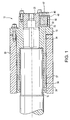
- Figure 1 is a side view of the disclosed embodiment of the invention, shown partly in cross-section, taken along line B-B of Figure 2 .
- Figure 2 is an end view of the disclosed embodiment.
- the conventional printing shaft is shown at 10.
- the hydraulic clamp 12 comprises a hydraulic hub 15.
- Printing cylinder 20 is mounted on the hydraulic hub 15 in known fashion.
- An outer hub 25 is provided on the hydraulic hub 15.
- the hydraulic hub 15 provides for fine positioning of the printing cylinder 20 for proper printing, again in known fashion.
- the hydraulic hub 15 has a circumferential annular recess 36 defined by at least one expandable outer wall 37 and an expandable inner wall 38. When the recess 36 is pressurized, the inner wall 38 clamps onto the shaft 10 and the outer wall 37 clamps against the inside diameter of the printing cylinder at the same time.
- the hydraulic hub 15 further has a single, large-diameter pressure screw 30 which moves a piston 32 for compressing hydraulic fluid in a hydraulic chamber or recess 33.
- the hydraulic chamber or recess 33 communicates via a passage 34 with the circumferential chamber or recess 36.
- the present invention requires only a single, axially arranged screw 30 for pressurizing the hydraulic chamber or recess 36. Therefore, the hydraulic clamp 12 can be more easily released from the shaft 10 by a single unscrewing operation, which can be carried out with the operator at a location safely spaced away from the end of the shaft in the axial direction.
- the pressure screw 30 has an enlarged flange 40 on its outside end.
- the combination of the screw 30 and the flange 40 limits the travel of the screw and piston 32 into the chamber 33 and thus prevents potential overpressure or binding or jamming in the chamber 33.
- a stop plate 45 mounted on the outer hub 25 is a stop plate 45.
- the stop plate 45 has a hole 47 for permitting insertion of a tool for actuating the pressure screw 30.
- the stop plate 45 also prevents the pressure screw 30 from being unscrewed too far from the chamber 32 and potentially lost.
- the flange 40 and the stop plate 45 limit the travel of the screw 30 both into and out of the chamber 33. With these limits being automatically provided, the operator is able to move the screw 30 either into or out of the chamber 33 with a minimum of thought and judgment being required, and therefore rapidly and conveniently.
- FIG. 2 the front face of the hydraulic clamp 12 is shown. Adjustment members for fine image registration are mounted on the front face. A screw 52 allows for lateral inward adjustment. A screw 54 provides lateral outward adjustment. An eccentric stud 50 provides for radial registration.
Landscapes
- Engineering & Computer Science (AREA)
- General Engineering & Computer Science (AREA)
- Physics & Mathematics (AREA)
- Fluid Mechanics (AREA)
- Mechanical Engineering (AREA)
- Clamps And Clips (AREA)
- Jigs For Machine Tools (AREA)
Claims (5)
- Hydraulikklemme (12) zum Anbringen an einer Welle (10), wobei die Klemme (12) Folgendes umfasst:eine Hydrauliknabe (15);eine Öffnung in der Hydrauliknabe (15) zur Aufnahme der Welle (10), wobei sich die Öffnung in Axialrichtung der Hydrauliknabe (15) von deren erstem Ende zu deren zweitem Ende erstreckt; undeine in der Hydrauliknabe (15) ausgebildete Aussparung (36), die im Wesentlichen die Öffnung umgibt, zur Aufnahme eines Druckmediums;wobei die Hydrauliknabe (15) an ihrem ersten Ende eine einzelne Druckschraube (30) und einen entsprechenden einzelnen Kolben (32) in einer Aussparung oder Kammer (33) aufweist, der mit der Aussparung (36) kommuniziert, um das Druckmedium mit Druck zu beaufschlagen und dadurch die Aussparung (36) hinreichend zu verformen, um die Klemme an der Welle (10) festzulegen,wobei der einzelne Kolben (32) zur Axialbewegung in Richtung des zweiten Endes mithilfe der Schraube (30) angeordnet ist, um das Druckmedium mit Druck zu beaufschlagen,dadurch gekennzeichnet, dass:die Klemme ferner eine Anschlagplatte (45) umfasst, die am ersten Ende der Hydrauliknabe (15) angebracht ist, um eine vorbestimmte Begrenzung für die Axialbewegung der einzelnen Druckschraube (30) weg vom zweiten Ende einzuhalten.
- Hydraulikklemme (12) nach Anspruch 1, worin die Schraube (30) ferner einen Flansch (40) mit einer Außenfläche umfasst, der auf der Schraube (30) ausgebildet ist, um mit der Anschlagplatte (45) in Eingriff zu gelangen, wodurch die vorbestimmte Begrenzung für die Axialbewegung der Schraube (30) eingehalten wird.
- Hydraulikklemme (12) nach Anspruch 1, worin die Anschlagplatte (45) ein Loch (47) aufweist, das axial zu der Schraube (30) angeordnet ist, wobei das Loch (47) es einem Werkzeug ermöglicht, auf die Schraube (30) zuzugreifen, indem es im Wesentlichen in der Axialrichtung eingebracht wird.
- Hydraulikklemme (12) nach Anspruch 1 und in der Öffnung in der Hydrauliknabe (15) aufgenommene Welle (10) in Kombination.
- Zylindrischer Druckkopf (20) und Hydrauliknabe (15) gemäß einem der Ansprüche 1 bis 3 in Kombination oder gemäß einer Kombination nach Anspruch 4, wobei die Nabe (15) an dem Druckkopf (20) befestigt ist, um den Druckkopf (20) auf der Welle (10) zu befestigen.
Applications Claiming Priority (3)
| Application Number | Priority Date | Filing Date | Title |
|---|---|---|---|
| US42067302P | 2002-10-22 | 2002-10-22 | |
| US420673P | 2002-10-22 | ||
| PCT/US2003/032608 WO2004038246A2 (en) | 2002-10-22 | 2003-10-15 | Plate cylinder locking mechanism |
Publications (3)
| Publication Number | Publication Date |
|---|---|
| EP1558854A2 EP1558854A2 (de) | 2005-08-03 |
| EP1558854A4 EP1558854A4 (de) | 2007-08-22 |
| EP1558854B1 true EP1558854B1 (de) | 2013-09-18 |
Family
ID=32176606
Family Applications (1)
| Application Number | Title | Priority Date | Filing Date |
|---|---|---|---|
| EP03777618.4A Expired - Lifetime EP1558854B1 (de) | 2002-10-22 | 2003-10-15 | Plattenzylinderverriegelungssystem |
Country Status (4)
| Country | Link |
|---|---|
| US (1) | US20070074634A1 (de) |
| EP (1) | EP1558854B1 (de) |
| AU (1) | AU2003287095A1 (de) |
| WO (1) | WO2004038246A2 (de) |
Families Citing this family (1)
| Publication number | Priority date | Publication date | Assignee | Title |
|---|---|---|---|---|
| EP2837841A1 (de) | 2013-08-14 | 2015-02-18 | Ando, Mahito | Schrumpfscheibe |
Family Cites Families (19)
| Publication number | Priority date | Publication date | Assignee | Title |
|---|---|---|---|---|
| US2587606A (en) * | 1946-06-11 | 1952-03-04 | Dungler Julien | Cylinder adjusting means for machines for printing fabrics, paper, and other materials |
| US3547244A (en) * | 1968-09-30 | 1970-12-15 | Eaton Yale & Towne | Sleeve clutch |
| US3861815A (en) * | 1972-12-04 | 1975-01-21 | Kjell Gustav Landaeus | Arrangement for releasably mounting of a hub or a wheel on a shaft |
| US4093052A (en) * | 1974-01-23 | 1978-06-06 | Forenade Fabriksverken | Fluid actuated coupling assembly |
| SE7812703L (sv) * | 1978-12-11 | 1980-06-12 | Hans Otto Olsson | Anordning vid hydrauliska kopplingar |
| US4381709A (en) * | 1980-06-13 | 1983-05-03 | Robert Katz | Printing roller with removable cylinder |
| US4386566A (en) * | 1980-10-06 | 1983-06-07 | Mosstype Corporation | Mandrel assembly for demountable printing cylinder |
| SE442665B (sv) * | 1983-05-24 | 1986-01-20 | Metalform Safeset Ab | Transmission |
| DE3326934A1 (de) * | 1983-07-26 | 1985-02-07 | Siemens AG, 1000 Berlin und 8000 München | Aufnahmevorrichtung und geraeteeinsatz fuer die nachrichtentechnik |
| US4624184A (en) * | 1984-03-27 | 1986-11-25 | Sidney Katz | Annular expansible heads for a printing cylinder assembly |
| US4651643A (en) * | 1985-02-14 | 1987-03-24 | Sidney Katz | Adaptors for use with printing cylinder mandrels |
| JP2928841B2 (ja) * | 1989-05-02 | 1999-08-03 | 日本ヒューレット・パッカード株式会社 | 電極システム |
| DE9100115U1 (de) * | 1991-01-07 | 1991-03-28 | ETP Transmission AB, Linköping | Aus Werkzeug und Werkzeugfutter bestehende Vorrichtung |
| US5127431A (en) * | 1991-05-08 | 1992-07-07 | The Coca-Cola Company | Flow control system for a beverage dispenser |
| US5507228A (en) * | 1994-10-03 | 1996-04-16 | Schulz; Werner | Printing cylinder |
| US5537923A (en) * | 1995-05-24 | 1996-07-23 | Huntsman Packaging Corporation | Printing sleeve air pressure mounting apparatus |
| US5819648A (en) | 1996-09-12 | 1998-10-13 | American National Can Company | Two piece printing head for decorator cylinder with tapered shaft |
| SE512052C2 (sv) | 1997-04-11 | 2000-01-17 | Etp Transmission Ab | Hydraulisk spännbussning |
| US6363850B1 (en) * | 1999-11-22 | 2002-04-02 | Mceachern David A. | Mounting printing plate cylinder having tapered bore to untapered rotatable drive shaft |
-
2003
- 2003-10-15 AU AU2003287095A patent/AU2003287095A1/en not_active Abandoned
- 2003-10-15 US US10/548,746 patent/US20070074634A1/en not_active Abandoned
- 2003-10-15 EP EP03777618.4A patent/EP1558854B1/de not_active Expired - Lifetime
- 2003-10-15 WO PCT/US2003/032608 patent/WO2004038246A2/en not_active Ceased
Also Published As
| Publication number | Publication date |
|---|---|
| WO2004038246A3 (en) | 2004-06-24 |
| AU2003287095A8 (en) | 2004-05-13 |
| EP1558854A4 (de) | 2007-08-22 |
| WO2004038246A2 (en) | 2004-05-06 |
| EP1558854A2 (de) | 2005-08-03 |
| US20070074634A1 (en) | 2007-04-05 |
| AU2003287095A1 (en) | 2004-05-13 |
Similar Documents
| Publication | Publication Date | Title |
|---|---|---|
| EP2196274B1 (de) | Werkzeughalter | |
| JP3825747B2 (ja) | 固締装置および方法 | |
| US7059030B2 (en) | Pressing device | |
| WO2005035998B1 (en) | Hydraulic nut | |
| US5658192A (en) | Arrangement and corresponding adapter for receiving a rotating body in a centered and axially fixed manner | |
| SE511085C2 (sv) | Hydromekanisk chuck | |
| JPS61230867A (ja) | 砥石車用締付装置 | |
| US20230405689A1 (en) | Self-locking clamping system for a hollow shaft | |
| US12280437B2 (en) | Clamping device for tool holder | |
| JP7583748B2 (ja) | ツールホルダ用のクランピングデバイス | |
| US6260393B1 (en) | Hole punch for high-pressure shaping tool | |
| US5537923A (en) | Printing sleeve air pressure mounting apparatus | |
| US4244534A (en) | Strip coiler | |
| US5163250A (en) | Securing apparatus for tools | |
| US20070074634A1 (en) | Plate cylinder locking mechanism | |
| US6179303B1 (en) | Device for accomodating a tool or a support element in a machine tool or a spindle | |
| US6647879B1 (en) | Bridge sleeve for printing apparatus | |
| US4434883A (en) | Device for shaft alignment in a clutch or brake assembly | |
| EP0684884B1 (de) | Spannvorrichtung für fräser oder ähnliche, anpassbar für verschiedene haltergrössen | |
| EP0963268B1 (de) | Präzisionshydraulikfutter | |
| WO1998032562B1 (en) | Hydraulic precision mandrel | |
| JP2003506223A (ja) | 軸の上に構成部材を解離可能に固定する緊締する装置 | |
| GB2034639A (en) | Printing machine cylinder with detachable bearing ring | |
| CN210757340U (zh) | 一种组合式内孔定位器 | |
| EP3481573B1 (de) | Montagezusammensetzung vn einem werkzeug und verwendung |
Legal Events
| Date | Code | Title | Description |
|---|---|---|---|
| PUAI | Public reference made under article 153(3) epc to a published international application that has entered the european phase |
Free format text: ORIGINAL CODE: 0009012 |
|
| 17P | Request for examination filed |
Effective date: 20050502 |
|
| AK | Designated contracting states |
Kind code of ref document: A2 Designated state(s): AT BE BG CH CY CZ DE DK EE ES FI FR GB GR HU IE IT LI LU MC NL PT RO SE SI SK TR |
|
| AX | Request for extension of the european patent |
Extension state: AL LT LV MK |
|
| DAX | Request for extension of the european patent (deleted) | ||
| A4 | Supplementary search report drawn up and despatched |
Effective date: 20070719 |
|
| RIC1 | Information provided on ipc code assigned before grant |
Ipc: F16D 1/08 20060101AFI20070713BHEP Ipc: B41F 17/22 20060101ALI20070713BHEP |
|
| 17Q | First examination report despatched |
Effective date: 20091116 |
|
| GRAP | Despatch of communication of intention to grant a patent |
Free format text: ORIGINAL CODE: EPIDOSNIGR1 |
|
| INTG | Intention to grant announced |
Effective date: 20130408 |
|
| GRAS | Grant fee paid |
Free format text: ORIGINAL CODE: EPIDOSNIGR3 |
|
| GRAA | (expected) grant |
Free format text: ORIGINAL CODE: 0009210 |
|
| AK | Designated contracting states |
Kind code of ref document: B1 Designated state(s): AT BE BG CH CY CZ DE DK EE ES FI FR GB GR HU IE IT LI LU MC NL PT RO SE SI SK TR |
|
| REG | Reference to a national code |
Ref country code: GB Ref legal event code: FG4D |
|
| REG | Reference to a national code |
Ref country code: CH Ref legal event code: EP |
|
| REG | Reference to a national code |
Ref country code: IE Ref legal event code: FG4D |
|
| REG | Reference to a national code |
Ref country code: AT Ref legal event code: REF Ref document number: 632961 Country of ref document: AT Kind code of ref document: T Effective date: 20131015 |
|
| REG | Reference to a national code |
Ref country code: DE Ref legal event code: R096 Ref document number: 60344960 Country of ref document: DE Effective date: 20131114 |
|
| REG | Reference to a national code |
Ref country code: NL Ref legal event code: T3 |
|
| PG25 | Lapsed in a contracting state [announced via postgrant information from national office to epo] |
Ref country code: SE Free format text: LAPSE BECAUSE OF FAILURE TO SUBMIT A TRANSLATION OF THE DESCRIPTION OR TO PAY THE FEE WITHIN THE PRESCRIBED TIME-LIMIT Effective date: 20130918 Ref country code: CY Free format text: LAPSE BECAUSE OF FAILURE TO SUBMIT A TRANSLATION OF THE DESCRIPTION OR TO PAY THE FEE WITHIN THE PRESCRIBED TIME-LIMIT Effective date: 20130703 |
|
| REG | Reference to a national code |
Ref country code: AT Ref legal event code: MK05 Ref document number: 632961 Country of ref document: AT Kind code of ref document: T Effective date: 20130918 |
|
| PG25 | Lapsed in a contracting state [announced via postgrant information from national office to epo] |
Ref country code: GR Free format text: LAPSE BECAUSE OF FAILURE TO SUBMIT A TRANSLATION OF THE DESCRIPTION OR TO PAY THE FEE WITHIN THE PRESCRIBED TIME-LIMIT Effective date: 20131219 Ref country code: SI Free format text: LAPSE BECAUSE OF FAILURE TO SUBMIT A TRANSLATION OF THE DESCRIPTION OR TO PAY THE FEE WITHIN THE PRESCRIBED TIME-LIMIT Effective date: 20130918 Ref country code: FI Free format text: LAPSE BECAUSE OF FAILURE TO SUBMIT A TRANSLATION OF THE DESCRIPTION OR TO PAY THE FEE WITHIN THE PRESCRIBED TIME-LIMIT Effective date: 20130918 |
|
| PG25 | Lapsed in a contracting state [announced via postgrant information from national office to epo] |
Ref country code: CY Free format text: LAPSE BECAUSE OF FAILURE TO SUBMIT A TRANSLATION OF THE DESCRIPTION OR TO PAY THE FEE WITHIN THE PRESCRIBED TIME-LIMIT Effective date: 20130918 Ref country code: BE Free format text: LAPSE BECAUSE OF FAILURE TO SUBMIT A TRANSLATION OF THE DESCRIPTION OR TO PAY THE FEE WITHIN THE PRESCRIBED TIME-LIMIT Effective date: 20130918 |
|
| PG25 | Lapsed in a contracting state [announced via postgrant information from national office to epo] |
Ref country code: RO Free format text: LAPSE BECAUSE OF FAILURE TO SUBMIT A TRANSLATION OF THE DESCRIPTION OR TO PAY THE FEE WITHIN THE PRESCRIBED TIME-LIMIT Effective date: 20130918 Ref country code: EE Free format text: LAPSE BECAUSE OF FAILURE TO SUBMIT A TRANSLATION OF THE DESCRIPTION OR TO PAY THE FEE WITHIN THE PRESCRIBED TIME-LIMIT Effective date: 20130918 Ref country code: SK Free format text: LAPSE BECAUSE OF FAILURE TO SUBMIT A TRANSLATION OF THE DESCRIPTION OR TO PAY THE FEE WITHIN THE PRESCRIBED TIME-LIMIT Effective date: 20130918 Ref country code: CZ Free format text: LAPSE BECAUSE OF FAILURE TO SUBMIT A TRANSLATION OF THE DESCRIPTION OR TO PAY THE FEE WITHIN THE PRESCRIBED TIME-LIMIT Effective date: 20130918 |
|
| PG25 | Lapsed in a contracting state [announced via postgrant information from national office to epo] |
Ref country code: AT Free format text: LAPSE BECAUSE OF FAILURE TO SUBMIT A TRANSLATION OF THE DESCRIPTION OR TO PAY THE FEE WITHIN THE PRESCRIBED TIME-LIMIT Effective date: 20130918 Ref country code: ES Free format text: LAPSE BECAUSE OF FAILURE TO SUBMIT A TRANSLATION OF THE DESCRIPTION OR TO PAY THE FEE WITHIN THE PRESCRIBED TIME-LIMIT Effective date: 20130918 |
|
| REG | Reference to a national code |
Ref country code: CH Ref legal event code: PL |
|
| REG | Reference to a national code |
Ref country code: DE Ref legal event code: R097 Ref document number: 60344960 Country of ref document: DE |
|
| PG25 | Lapsed in a contracting state [announced via postgrant information from national office to epo] |
Ref country code: MC Free format text: LAPSE BECAUSE OF FAILURE TO SUBMIT A TRANSLATION OF THE DESCRIPTION OR TO PAY THE FEE WITHIN THE PRESCRIBED TIME-LIMIT Effective date: 20130918 Ref country code: PT Free format text: LAPSE BECAUSE OF FAILURE TO SUBMIT A TRANSLATION OF THE DESCRIPTION OR TO PAY THE FEE WITHIN THE PRESCRIBED TIME-LIMIT Effective date: 20140120 |
|
| PLBE | No opposition filed within time limit |
Free format text: ORIGINAL CODE: 0009261 |
|
| STAA | Information on the status of an ep patent application or granted ep patent |
Free format text: STATUS: NO OPPOSITION FILED WITHIN TIME LIMIT |
|
| REG | Reference to a national code |
Ref country code: IE Ref legal event code: MM4A |
|
| PG25 | Lapsed in a contracting state [announced via postgrant information from national office to epo] |
Ref country code: CH Free format text: LAPSE BECAUSE OF NON-PAYMENT OF DUE FEES Effective date: 20131031 Ref country code: LI Free format text: LAPSE BECAUSE OF NON-PAYMENT OF DUE FEES Effective date: 20131031 |
|
| REG | Reference to a national code |
Ref country code: FR Ref legal event code: ST Effective date: 20140630 |
|
| 26N | No opposition filed |
Effective date: 20140619 |
|
| PG25 | Lapsed in a contracting state [announced via postgrant information from national office to epo] |
Ref country code: IT Free format text: LAPSE BECAUSE OF FAILURE TO SUBMIT A TRANSLATION OF THE DESCRIPTION OR TO PAY THE FEE WITHIN THE PRESCRIBED TIME-LIMIT Effective date: 20130918 Ref country code: FR Free format text: LAPSE BECAUSE OF NON-PAYMENT OF DUE FEES Effective date: 20131118 |
|
| REG | Reference to a national code |
Ref country code: DE Ref legal event code: R097 Ref document number: 60344960 Country of ref document: DE Effective date: 20140619 |
|
| PG25 | Lapsed in a contracting state [announced via postgrant information from national office to epo] |
Ref country code: DK Free format text: LAPSE BECAUSE OF FAILURE TO SUBMIT A TRANSLATION OF THE DESCRIPTION OR TO PAY THE FEE WITHIN THE PRESCRIBED TIME-LIMIT Effective date: 20130918 |
|
| PG25 | Lapsed in a contracting state [announced via postgrant information from national office to epo] |
Ref country code: IE Free format text: LAPSE BECAUSE OF NON-PAYMENT OF DUE FEES Effective date: 20131015 |
|
| PG25 | Lapsed in a contracting state [announced via postgrant information from national office to epo] |
Ref country code: TR Free format text: LAPSE BECAUSE OF FAILURE TO SUBMIT A TRANSLATION OF THE DESCRIPTION OR TO PAY THE FEE WITHIN THE PRESCRIBED TIME-LIMIT Effective date: 20130918 |
|
| PG25 | Lapsed in a contracting state [announced via postgrant information from national office to epo] |
Ref country code: HU Free format text: LAPSE BECAUSE OF FAILURE TO SUBMIT A TRANSLATION OF THE DESCRIPTION OR TO PAY THE FEE WITHIN THE PRESCRIBED TIME-LIMIT; INVALID AB INITIO Effective date: 20031015 Ref country code: LU Free format text: LAPSE BECAUSE OF NON-PAYMENT OF DUE FEES Effective date: 20131015 Ref country code: BG Free format text: LAPSE BECAUSE OF FAILURE TO SUBMIT A TRANSLATION OF THE DESCRIPTION OR TO PAY THE FEE WITHIN THE PRESCRIBED TIME-LIMIT Effective date: 20130918 |
|
| PGFP | Annual fee paid to national office [announced via postgrant information from national office to epo] |
Ref country code: NL Payment date: 20220916 Year of fee payment: 20 Ref country code: GB Payment date: 20220901 Year of fee payment: 20 |
|
| PGFP | Annual fee paid to national office [announced via postgrant information from national office to epo] |
Ref country code: DE Payment date: 20220831 Year of fee payment: 20 |
|
| P01 | Opt-out of the competence of the unified patent court (upc) registered |
Effective date: 20230429 |
|
| REG | Reference to a national code |
Ref country code: DE Ref legal event code: R071 Ref document number: 60344960 Country of ref document: DE |
|
| REG | Reference to a national code |
Ref country code: NL Ref legal event code: MK Effective date: 20231014 |
|
| REG | Reference to a national code |
Ref country code: GB Ref legal event code: PE20 Expiry date: 20231014 |
|
| PG25 | Lapsed in a contracting state [announced via postgrant information from national office to epo] |
Ref country code: GB Free format text: LAPSE BECAUSE OF EXPIRATION OF PROTECTION Effective date: 20231014 |
|
| PG25 | Lapsed in a contracting state [announced via postgrant information from national office to epo] |
Ref country code: GB Free format text: LAPSE BECAUSE OF EXPIRATION OF PROTECTION Effective date: 20231014 |