EP1558342B1 - Anchoring device - Google Patents
Anchoring device Download PDFInfo
- Publication number
- EP1558342B1 EP1558342B1 EP03769098A EP03769098A EP1558342B1 EP 1558342 B1 EP1558342 B1 EP 1558342B1 EP 03769098 A EP03769098 A EP 03769098A EP 03769098 A EP03769098 A EP 03769098A EP 1558342 B1 EP1558342 B1 EP 1558342B1
- Authority
- EP
- European Patent Office
- Prior art keywords
- housing
- anchoring device
- receptacle
- jaws
- locking
- Prior art date
- Legal status (The legal status is an assumption and is not a legal conclusion. Google has not performed a legal analysis and makes no representation as to the accuracy of the status listed.)
- Expired - Lifetime
Links
- 238000004873 anchoring Methods 0.000 title claims abstract description 38
- 238000005266 casting Methods 0.000 claims description 23
- 230000006835 compression Effects 0.000 claims description 3
- 238000007906 compression Methods 0.000 claims description 3
- 230000000712 assembly Effects 0.000 abstract description 3
- 238000000429 assembly Methods 0.000 abstract description 3
- 238000003780 insertion Methods 0.000 description 2
- 230000037431 insertion Effects 0.000 description 2
- 239000004677 Nylon Substances 0.000 description 1
- 229910000831 Steel Inorganic materials 0.000 description 1
- 230000000994 depressogenic effect Effects 0.000 description 1
- 238000012986 modification Methods 0.000 description 1
- 230000004048 modification Effects 0.000 description 1
- 229920001778 nylon Polymers 0.000 description 1
- 239000010959 steel Substances 0.000 description 1
Images


Classifications
-
- A—HUMAN NECESSITIES
- A62—LIFE-SAVING; FIRE-FIGHTING
- A62B—DEVICES, APPARATUS OR METHODS FOR LIFE-SAVING
- A62B35/00—Safety belts or body harnesses; Similar equipment for limiting displacement of the human body, especially in case of sudden changes of motion
- A62B35/0043—Lifelines, lanyards, and anchors therefore
- A62B35/0068—Anchors
Definitions
- the invention relates to an anchoring device to which personnel safety lines may be attached.
- the anchoring device is particularly adapted for use with the fixed castings or receptacles commonly found on cargo containers and the decks of ships. More specifically, the anchoring device is releasably secured within the casting.
- each container is provided at each corner with top and/or side casting or female receptacles to enable the container to be lifted using a lifting beam or spreader having twist locks or a mechanical equivalent at each of the four corners.
- the twist locks have male connections which are lowered or inserted sideways into engagement with the corner castings.
- An exemplary twist lock is described in U.S. Patent No. 3,749,438 to Loomis et al. This patent also provides useful background information on the art of handling cargo containers in general. Furthermore, such castings are also usually provided on the decks of container ships in order to facilitate container handling.
- the anchoring device is designed to be used in conjunction with a shock-absorbing lanyard or self-retracting lifeline which is attached to a personal safety harness fitted on the individual.
- the invention relates to an anchoring device having the features of claim 1.
- the invention comprises an anchoring device adapted to be utilized in combination with means for securing personnel to said anchoring device, said anchoring device further being adapted to be releasably secured within a receptacle sized to receive said anchoring device which comprises: a housing sized to be received within said receptacle; means for releasably securing said housing within said receptacle; and means associated with said housing for connecting said personnel securing means thereto.
- a portable anchoring device which is functional to automatically lock into the steel corner castings of shipping containers or the castings formed on the decks of container ships. Furthermore, the anchoring device is easily released from the locked position within the casting by simple depression of an actuator provided thereon.
- the anchoring device 10 of the present invention comprises a housing 12 provided with a pair of locking jaws 14 functional to releasably secure the anchoring device 10 within the cavity 11 of castings 16 set in the top corners or side walls of a cargo-carrying container 18, or ship's deck, or the like.
- Mounted on the top of the housing 12 is an anchor plate 20 to which may be releasably attached the lanyard or lifeline 80.
- a pivot pin 22 to which is operatively connected a handle socket 24 adapted to receive an elongated shaft 26, said shaft 26 being provided at its upper and distal end with a handle assembly generally designated 28 which is functional to actuate the locking jaws.
- the housing 12 comprises a generally U-shaped lower section 30 and an upper horizontal plate 32 defining a generally central circular aperture 31 therein.
- Plate 32 is sized to sit upon a portion of the upper wall or the side of the container 18 ( FIG. 6 ) surrounding the casting 16.
- a pair of V-shaped ribs 38 are mounted on the opposite outer walls 30a of the U-shaped lower section 30 of the housing 12 for guiding housing 12 into the cavity in casting 16.
- a pair of opposed locking jaws 14 are pivotally mounted within the housing 12 at their proximal ends by means of pivot pins 40 secured by rivets or nuts and bolts, not shown.
- the locking jaws 14 are retractable, their distal ends normally extending upwardly and outwardly from the open ends of U-shaped lower section 30, as viewed in FIG. 3 .
- Locking jaws 14 are generally rectangular in shape defining at their upper outer distal ends a square cut away portion 14a.
- a compression jack spring 42 extends between the lower sections 14b of the locking jaws 14 being secured thereto by insertion into opposed cavities 43, 43a.
- To each of connector pins 44a, 44b mounted on locking jaws 14 are secured the ends 46a and 46b respectively of a doubled-up release cable 46.
- the release cable ends 46a and 46b are guided in opposite directions over a diverter rod 48 secured by means of a cotter pin 50 ( FIG. 4 ).
- the cable ends 46a and 46b are suitably tensioned by means of compression spring 42 and the doubled-up cable 46 fed through a bore 56 defined in the pivot pin 22 which extends through aperture 31 of the housing top plate 32.
- the cable ends 46a and 46b are crimped to convertor pins 44a, 44b respectively as shown in FIG. 3 forming the unitary release cable 46, the operation of which being described hereinafter.
- the vertical pivot pin 22 defines an internal bore 56, forming at its lower end a circumferential flange 58 abutting the underside of plate 32.
- the oval anchor plate 20 Above the housing top plate 32 is mounted the oval anchor plate 20 which defines an upwardly extending lip 20a having a generally central circular aperture 36 defined therein.
- the aperture 36 is adapted to receive a carabiner 78 or the like to which may be attached the retractable shock-absorbing lanyard 80 or safety line ( FIG. 6 ).
- a pair of opposed rectangular plates 60 are provided on each side of the vertical pivot pin 22 being secured one to another by means of a nut and bolt assembly 62.
- the handle socket 24, sized to fit into plates 60 at an angle thereto, comprises a pair of opposed plates 61 having a sleeve 64 secured there between by means of nut and bolt assemblies 66.
- the release cable 46 extending vertically through the bore of pivot pin 22 is guided over a cable guide roller 68 upwardly through sleeve 64 and into the shaft 26 connected thereto.
- the shaft 26 extends angularly upwardly to the handle and locking jaw actuator assembly 28.
- pivot pin 22 is functional to permit rotation of the handle socket 24, shaft 26 and handle assembly 28 through an angle ⁇ of about 45 degrees on each side of the centre of the horizontal axis 29 of the casting 16.
- the handle and locking jaw actuator assembly 28 ( FIGS. 1 and 2 ) are made up as follows. To the shaft 26 is secured an industrial grip 29, the grip 29 having a trigger 67 which is pivotally mounted on the grip 29 in a pair of opposed tabs 31 formed on grip 29 and secured by means of rivets or a nut and bolt assembly 76. Trigger 67 is functional upon depression thereof for retraction of cable 46 to retract the locking jaws 14 inwardly towards each other, thus enabling the anchoring device 10 to be detached from the casting 16. More specifically, the doubled-up release cable 46 is attached to the lower end of nylon piston 70 extending internally through the grip 29. The piston 70 passes through an extension 74 formed at the distal end of the hand actuated trigger 67. The top of the piston 70 receives locking nut 72 which engages trigger extension 74 to enable lifting and extension of the release cable 46.
- the anchoring device 10 is guided downwardly or sideways into a cavity 11 receptacle of a casting 16 whereby the projecting ends of spring-loaded jaws 14 are depressed towards each other into housing 12 for outwardly snap-engagement with the underside of lip 100 of casting 16 ( FIG. 3 ), thereby locking anchoring device 10 into casting 16.
- the user is attached to housing 12 by a lanyard 80 secured thereto by carabiner 78.
- the user can quickly detach the anchoring device 10 from castings 16 by squeezing the trigger 67 as the distal ends of shaft 26 to extend cable 46 outwardly from handle assembly 28, thereby retracting normally outwardly-biased jaws 14 inwardly for release from casting lips 100.
- Handle 28 or shaft 26 can be pivoted through 90° of arc for convenience of access to the user.
- the anchoring device of the invention provides a safety anchor for personnel moving and working on stacked containers or on heaving ship decks.
- the anchoring device can be quickly guided and easily snapped into engagement with the castings and receptacles present on containers and ship decks and readily detached from the castings when desired by the user.
Landscapes
- Health & Medical Sciences (AREA)
- General Health & Medical Sciences (AREA)
- Business, Economics & Management (AREA)
- Emergency Management (AREA)
- Emergency Lowering Means (AREA)
- Joining Of Building Structures In Genera (AREA)
- Soil Working Implements (AREA)
- Piles And Underground Anchors (AREA)
Abstract
Description
- The invention relates to an anchoring device to which personnel safety lines may be attached. The anchoring device is particularly adapted for use with the fixed castings or receptacles commonly found on cargo containers and the decks of ships. More specifically, the anchoring device is releasably secured within the casting.
- The shipping and transportation of cargo in containerized units is a common world wide practice, the containers being loaded and unloaded onto ships, trucks, railway cars and the like.
- Typically, each container is provided at each corner with top and/or side casting or female receptacles to enable the container to be lifted using a lifting beam or spreader having twist locks or a mechanical equivalent at each of the four corners. The twist locks have male connections which are lowered or inserted sideways into engagement with the corner castings. An exemplary twist lock is described in
U.S. Patent No. 3,749,438 to Loomis et al. This patent also provides useful background information on the art of handling cargo containers in general. Furthermore, such castings are also usually provided on the decks of container ships in order to facilitate container handling. - The heights of stacked containers, either in the ship's hold or decks or on dry land, are dangerous for personnel moving on stacked containers or working on decks. In bad weather there exists a need to provide a personnel safety anchor to which a life line may be secured. This anchor, preferably, would be secured to the container or deck mechanically and provide means for securing a shock-absorbing lanyard or retractable safety line releasably thereto. In turn such a safety line would be attached to a full body harness worn by the individual. Document
WO 99/64110 - It is a primary objective of the present invention to provide an anchoring device which is adapted for insertion and removal into and from the top and side openings of corner castings on the roof or sides of a container or on a ship's deck. The anchoring device is designed to be used in conjunction with a shock-absorbing lanyard or self-retracting lifeline which is attached to a personal safety harness fitted on the individual.
- Accordingly the invention relates to an anchoring device having the features of
claim 1. - Broadly stated the invention comprises an anchoring device adapted to be utilized in combination with means for securing personnel to said anchoring device, said anchoring device further being adapted to be releasably secured within a receptacle sized to receive said anchoring device which comprises: a housing sized to be received within said receptacle; means for releasably securing said housing within said receptacle; and means associated with said housing for connecting said personnel securing means thereto.
- Advantageously, as a result of this invention there is provided a portable anchoring device which is functional to automatically lock into the steel corner castings of shipping containers or the castings formed on the decks of container ships. Furthermore, the anchoring device is easily released from the locked position within the casting by simple depression of an actuator provided thereon.
- The anchoring device of invention will now be described with reference to the accompanying drawings, in which:
- FIG.1
- is a perspective view of the anchoring device of the present invention;
- FIG.2
- is a side elevation view of the anchoring device of
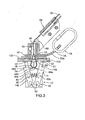
FIG.1 ; - FIG. 3
- is a sectional view of the housing and handle socket of the anchoring device, partly in elevation, taken through line 3-3 of
FIG. 1 ; - FIG. 4
- is an end elevation of the housing and pivot pin of the anchoring device of
FIG. 1 ; - FIG. 5
- is a plan view depicting the angle of travel of the handle assembly of the anchoring device of
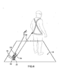
FIG. 1 ; and - FIG. 6
- is a perspective view of the anchoring device of
FIG. 1 depicting the device in its operating position secured in a container casting in combination with the shock-absorbing lanyard secured to a personal full body harness. - The invention can be anchored to the top or side openings of a container or ship. For purposes of clarity, the description focuses on the upright orientation of the invention. Having reference to the accompanying drawings, the
anchoring device 10 of the present invention comprises ahousing 12 provided with a pair oflocking jaws 14 functional to releasably secure theanchoring device 10 within thecavity 11 ofcastings 16 set in the top corners or side walls of a cargo-carryingcontainer 18, or ship's deck, or the like. Mounted on the top of thehousing 12 is ananchor plate 20 to which may be releasably attached the lanyard orlifeline 80. Above theanchor plate 20 extends apivot pin 22 to which is operatively connected ahandle socket 24 adapted to receive anelongated shaft 26, saidshaft 26 being provided at its upper and distal end with a handle assembly generally designated 28 which is functional to actuate the locking jaws. - Having particular reference to
FIG. 3 , thehousing 12 comprises a generally U-shapedlower section 30 and an upperhorizontal plate 32 defining a generally centralcircular aperture 31 therein.Plate 32 is sized to sit upon a portion of the upper wall or the side of the container 18 (FIG. 6 ) surrounding thecasting 16. A pair of V-shaped ribs 38 are mounted on the oppositeouter walls 30a of the U-shapedlower section 30 of thehousing 12 for guidinghousing 12 into the cavity incasting 16. A pair ofopposed locking jaws 14 are pivotally mounted within thehousing 12 at their proximal ends by means ofpivot pins 40 secured by rivets or nuts and bolts, not shown. Thelocking jaws 14 are retractable, their distal ends normally extending upwardly and outwardly from the open ends of U-shapedlower section 30, as viewed inFIG. 3 .Locking jaws 14 are generally rectangular in shape defining at their upper outer distal ends a square cut awayportion 14a. Acompression jack spring 42 extends between thelower sections 14b of thelocking jaws 14 being secured thereto by insertion intoopposed cavities connector pins locking jaws 14 are secured theends release cable 46. Therelease cable ends diverter rod 48 secured by means of a cotter pin 50 (FIG. 4 ). Thecable ends compression spring 42 and the doubled-upcable 46 fed through abore 56 defined in thepivot pin 22 which extends throughaperture 31 of thehousing top plate 32. Thecable ends convertor pins FIG. 3 forming theunitary release cable 46, the operation of which being described hereinafter. - As stated earlier, the
vertical pivot pin 22 defines aninternal bore 56, forming at its lower end acircumferential flange 58 abutting the underside ofplate 32. Above thehousing top plate 32 is mounted theoval anchor plate 20 which defines an upwardly extendinglip 20a having a generally centralcircular aperture 36 defined therein. Theaperture 36 is adapted to receive acarabiner 78 or the like to which may be attached the retractable shock-absorbinglanyard 80 or safety line (FIG. 6 ). - A pair of opposed rectangular plates 60 (
FIG. 2 ) are provided on each side of thevertical pivot pin 22 being secured one to another by means of a nut andbolt assembly 62. Thehandle socket 24, sized to fit intoplates 60 at an angle thereto, comprises a pair ofopposed plates 61 having asleeve 64 secured there between by means of nut andbolt assemblies 66. Therelease cable 46 extending vertically through the bore ofpivot pin 22 is guided over acable guide roller 68 upwardly throughsleeve 64 and into theshaft 26 connected thereto. Theshaft 26 extends angularly upwardly to the handle and lockingjaw actuator assembly 28. - As illustrated in
FIG. 5 ,pivot pin 22 is functional to permit rotation of thehandle socket 24,shaft 26 and handleassembly 28 through an angle α of about 45 degrees on each side of the centre of thehorizontal axis 29 of thecasting 16. - The handle and locking jaw actuator assembly 28 (
FIGS. 1 and2 ) are made up as follows. To theshaft 26 is secured anindustrial grip 29, thegrip 29 having atrigger 67 which is pivotally mounted on thegrip 29 in a pair ofopposed tabs 31 formed ongrip 29 and secured by means of rivets or a nut andbolt assembly 76.Trigger 67 is functional upon depression thereof for retraction ofcable 46 to retract thelocking jaws 14 inwardly towards each other, thus enabling theanchoring device 10 to be detached from thecasting 16. More specifically, the doubled-uprelease cable 46 is attached to the lower end ofnylon piston 70 extending internally through thegrip 29. Thepiston 70 passes through anextension 74 formed at the distal end of the hand actuatedtrigger 67. The top of thepiston 70 receives lockingnut 72 which engagestrigger extension 74 to enable lifting and extension of therelease cable 46. - In operation, the anchoring
device 10 is guided downwardly or sideways into acavity 11 receptacle of a casting 16 whereby the projecting ends of spring-loadedjaws 14 are depressed towards each other intohousing 12 for outwardly snap-engagement with the underside oflip 100 of casting 16 (FIG. 3 ), thereby lockinganchoring device 10 into casting 16. The user is attached tohousing 12 by alanyard 80 secured thereto bycarabiner 78. The user can quickly detach theanchoring device 10 fromcastings 16 by squeezing thetrigger 67 as the distal ends ofshaft 26 to extendcable 46 outwardly fromhandle assembly 28, thereby retracting normally outwardly-biasedjaws 14 inwardly for release from castinglips 100.Handle 28 orshaft 26 can be pivoted through 90° of arc for convenience of access to the user. - The anchoring device of the invention provides a safety anchor for personnel moving and working on stacked containers or on heaving ship decks. The anchoring device can be quickly guided and easily snapped into engagement with the castings and receptacles present on containers and ship decks and readily detached from the castings when desired by the user.
- It will be understood, of course, that modifications can be made in the embodiments of the invention described herein without departing from the scope and purview of the invention as defined by the appended claims.
Claims (3)
- Anchoring device adapted for releasable locking engagement within a receptacle (11) of a casting (16) on a container, said anchoring device being adapted for use with a personnel safety securing assembly and comprising:- a housing (12) comprising a lower section (30) having a pair of opposed spring-loaded releasable locking jaws (14) associated therewith, said locking jaws further having a releasable cable (46) secured thereto and being functional to extend into locking engagement within said receptacle (11), said housing comprising an upper plate (32) sized to seat against said receptacle;- a pivot pin (22), extending from within said housing through its upper plate (32) to a distance thereabove;- an anchor plate (20) mounted on top of the upper plate (32) and having an aperture (36) to receive the personnel safety security assembly;- a handle assembly (28) provided at the distal end of a shaft (26) and, said shaft being operatively connected to said pivot pin whereby said shaft may be rotated about the pivot pin (22) to an angle of up to about 45 degrees on each side thereof, said pivot pin (22) having a central bore (56) whereby said release cable (46) extends therethrough for operative engagement with a trigger (67) provided on said handle assembly (28) whereby actuation of the trigger functions to release said locking jaws (14) from within said receptacle (11).
- Anchoring device as claimed in claim 1, wherein said housing has a U-shaped lower section and in which said spring-loaded releasable locking jaws comprise a pair of opposed jaws pivotally-mounted at their lower ends in said U-shaped housing whereby upper ends of the jaws project outwardly from the U-shaped lower section for locking engagement with the receptacle.
- Anchoring device as claimed in claim 2, in which a compression spring operatively positioned between the locking jaws biases said locking jaws apart for normally spring loading of the jaws away from each other.
Applications Claiming Priority (3)
| Application Number | Priority Date | Filing Date | Title |
|---|---|---|---|
| US10/271,735 US6834745B2 (en) | 2002-10-17 | 2002-10-17 | Anchoring device |
| US271735 | 2002-10-17 | ||
| PCT/CA2003/001573 WO2004035140A1 (en) | 2002-10-17 | 2003-10-14 | Anchoring device |
Publications (2)
| Publication Number | Publication Date |
|---|---|
| EP1558342A1 EP1558342A1 (en) | 2005-08-03 |
| EP1558342B1 true EP1558342B1 (en) | 2011-11-23 |
Family
ID=32092516
Family Applications (1)
| Application Number | Title | Priority Date | Filing Date |
|---|---|---|---|
| EP03769098A Expired - Lifetime EP1558342B1 (en) | 2002-10-17 | 2003-10-14 | Anchoring device |
Country Status (6)
| Country | Link |
|---|---|
| US (1) | US6834745B2 (en) |
| EP (1) | EP1558342B1 (en) |
| AT (1) | ATE534434T1 (en) |
| AU (1) | AU2003278015A1 (en) |
| ES (1) | ES2377003T3 (en) |
| WO (1) | WO2004035140A1 (en) |
Cited By (1)
| Publication number | Priority date | Publication date | Assignee | Title |
|---|---|---|---|---|
| US12420122B2 (en) | 2019-11-04 | 2025-09-23 | Pure Safety Group, Inc. | Anchor device |
Families Citing this family (10)
| Publication number | Priority date | Publication date | Assignee | Title |
|---|---|---|---|---|
| US8919497B2 (en) * | 2008-11-07 | 2014-12-30 | Caterpillar Inc. | Powered operator access system |
| US8602160B2 (en) * | 2009-09-03 | 2013-12-10 | Rbi Acquisition Company | Safety anchor |
| JP5833942B2 (en) * | 2012-01-30 | 2015-12-16 | 株式会社ロッコーエンジニアリング | Safety support for work at height |
| US8635821B1 (en) | 2012-07-16 | 2014-01-28 | Michael C. Pierce | Safety line anchor securable to roof drain |
| US20140060967A1 (en) * | 2012-09-05 | 2014-03-06 | Honeywell International Inc. | Fall Protection System for Shipping Containers |
| US10118057B2 (en) | 2016-04-29 | 2018-11-06 | Auburn University | Fall restraint system |
| US9945128B1 (en) * | 2017-07-26 | 2018-04-17 | Robonail Llc | Automatic roof shingle removal and installation system |
| US10967209B2 (en) | 2018-03-01 | 2021-04-06 | 3M Innovative Properties Company | Anchorage assembly and method of using |
| US12011624B1 (en) * | 2019-07-12 | 2024-06-18 | Nance Solutions, Inc. | Personnel safety cable mount assembly |
| US20230021139A1 (en) * | 2021-07-19 | 2023-01-19 | Nawar Kzeer | Roof Anchor |
Family Cites Families (8)
| Publication number | Priority date | Publication date | Assignee | Title |
|---|---|---|---|---|
| US3263629A (en) * | 1964-10-15 | 1966-08-02 | Davis Aircraft Products Inc | Cargo tiedown fitting |
| GB1208675A (en) * | 1968-03-13 | 1970-10-14 | Hutsons Ltd | Improvements in coupling devices for interconnecting straddle slings to cargo containers |
| GB1280675A (en) | 1969-05-23 | 1972-07-05 | Scovill Manufacturing Co | Improved device for use in controlled evacuation and charging of fluid from or into containers |
| US3749438A (en) | 1971-04-05 | 1973-07-31 | Fruehauf Corp | Twist lock |
| NO178258C (en) | 1993-02-24 | 1996-02-21 | Tor Dalene | hoisting lug |
| WO1999064110A1 (en) | 1998-06-10 | 1999-12-16 | Unique Concepts Ltd. | Mounting post for a safety harness |
| FR2803341B1 (en) | 2000-01-05 | 2002-03-22 | Dalloz Fall Prot | ANCHORING DEVICE ON CONTAINERS |
| US20040035992A1 (en) * | 2002-08-23 | 2004-02-26 | Watts Allan W. | Rock-anchoring devices with non-metal components |
-
2002
- 2002-10-17 US US10/271,735 patent/US6834745B2/en not_active Expired - Lifetime
-
2003
- 2003-10-14 AU AU2003278015A patent/AU2003278015A1/en not_active Abandoned
- 2003-10-14 EP EP03769098A patent/EP1558342B1/en not_active Expired - Lifetime
- 2003-10-14 ES ES03769098T patent/ES2377003T3/en not_active Expired - Lifetime
- 2003-10-14 AT AT03769098T patent/ATE534434T1/en active
- 2003-10-14 WO PCT/CA2003/001573 patent/WO2004035140A1/en not_active Ceased
Cited By (1)
| Publication number | Priority date | Publication date | Assignee | Title |
|---|---|---|---|---|
| US12420122B2 (en) | 2019-11-04 | 2025-09-23 | Pure Safety Group, Inc. | Anchor device |
Also Published As
| Publication number | Publication date |
|---|---|
| US6834745B2 (en) | 2004-12-28 |
| ATE534434T1 (en) | 2011-12-15 |
| ES2377003T3 (en) | 2012-03-21 |
| US20040074695A1 (en) | 2004-04-22 |
| WO2004035140A1 (en) | 2004-04-29 |
| AU2003278015A1 (en) | 2004-05-04 |
| EP1558342A1 (en) | 2005-08-03 |
Similar Documents
| Publication | Publication Date | Title |
|---|---|---|
| EP1558342B1 (en) | Anchoring device | |
| CN102036887B (en) | Shipping container locking system and device for unlocking container twist locks | |
| US7014234B2 (en) | Integrated corner casting locking mechanism for shipping containers | |
| US7399148B2 (en) | Fastening device for securing a container to a ship | |
| US4925226A (en) | Manually operated cargo container hook apparatus | |
| CA1162387A (en) | Retractable lift ring | |
| CN105408217B (en) | Container securing system with pressure and torque transmission | |
| US5261559A (en) | Gas cylinder ring assembly | |
| US10322504B2 (en) | Tool for use with shipping containers and methods of using the same | |
| US20080290676A1 (en) | Spreader Frame for Cargo Container | |
| US5004071A (en) | Adaptor bracket | |
| US7648183B2 (en) | Latching apparatus and method | |
| US20090301983A1 (en) | Crane for handling of chains,wires,etc., and tools for same | |
| US11795035B2 (en) | Lifting device and methods for pulling up overturned vehicles and other structures | |
| US20220033230A1 (en) | Remote release shackle for choker hitch | |
| US4655153A (en) | Portable stanchion for ships | |
| AU742736B2 (en) | Retractable corner casting fastener | |
| Andersson | Container lashing | |
| AU746207B2 (en) | Twistlock | |
| US20170299247A1 (en) | Water cooler transport device | |
| NO840138L (en) | SAFETY HOOK | |
| NZ237730A (en) | Remotely controlled lifting tackle with hydraulic or pneumatic hook release mechanism |
Legal Events
| Date | Code | Title | Description |
|---|---|---|---|
| PUAI | Public reference made under article 153(3) epc to a published international application that has entered the european phase |
Free format text: ORIGINAL CODE: 0009012 |
|
| 17P | Request for examination filed |
Effective date: 20050517 |
|
| AK | Designated contracting states |
Kind code of ref document: A1 Designated state(s): AT BE BG CH CY CZ DE DK EE ES FI FR GB GR HU IE IT LI LU MC NL PT RO SE SI SK TR |
|
| AX | Request for extension of the european patent |
Extension state: AL LT LV MK |
|
| DAX | Request for extension of the european patent (deleted) | ||
| 17Q | First examination report despatched |
Effective date: 20100512 |
|
| GRAP | Despatch of communication of intention to grant a patent |
Free format text: ORIGINAL CODE: EPIDOSNIGR1 |
|
| GRAS | Grant fee paid |
Free format text: ORIGINAL CODE: EPIDOSNIGR3 |
|
| GRAA | (expected) grant |
Free format text: ORIGINAL CODE: 0009210 |
|
| AK | Designated contracting states |
Kind code of ref document: B1 Designated state(s): AT BE BG CH CY CZ DE DK EE ES FI FR GB GR HU IE IT LI LU MC NL PT RO SE SI SK TR |
|
| REG | Reference to a national code |
Ref country code: GB Ref legal event code: FG4D |
|
| REG | Reference to a national code |
Ref country code: CH Ref legal event code: EP |
|
| REG | Reference to a national code |
Ref country code: IE Ref legal event code: FG4D |
|
| REG | Reference to a national code |
Ref country code: SE Ref legal event code: TRGR |
|
| REG | Reference to a national code |
Ref country code: DE Ref legal event code: R096 Ref document number: 60339221 Country of ref document: DE Effective date: 20120126 |
|
| REG | Reference to a national code |
Ref country code: NL Ref legal event code: T3 |
|
| REG | Reference to a national code |
Ref country code: ES Ref legal event code: FG2A Ref document number: 2377003 Country of ref document: ES Kind code of ref document: T3 Effective date: 20120321 |
|
| PG25 | Lapsed in a contracting state [announced via postgrant information from national office to epo] |
Ref country code: SI Free format text: LAPSE BECAUSE OF FAILURE TO SUBMIT A TRANSLATION OF THE DESCRIPTION OR TO PAY THE FEE WITHIN THE PRESCRIBED TIME-LIMIT Effective date: 20111123 Ref country code: GR Free format text: LAPSE BECAUSE OF FAILURE TO SUBMIT A TRANSLATION OF THE DESCRIPTION OR TO PAY THE FEE WITHIN THE PRESCRIBED TIME-LIMIT Effective date: 20120224 Ref country code: PT Free format text: LAPSE BECAUSE OF FAILURE TO SUBMIT A TRANSLATION OF THE DESCRIPTION OR TO PAY THE FEE WITHIN THE PRESCRIBED TIME-LIMIT Effective date: 20120323 |
|
| PG25 | Lapsed in a contracting state [announced via postgrant information from national office to epo] |
Ref country code: CY Free format text: LAPSE BECAUSE OF FAILURE TO SUBMIT A TRANSLATION OF THE DESCRIPTION OR TO PAY THE FEE WITHIN THE PRESCRIBED TIME-LIMIT Effective date: 20111123 |
|
| PG25 | Lapsed in a contracting state [announced via postgrant information from national office to epo] |
Ref country code: DK Free format text: LAPSE BECAUSE OF FAILURE TO SUBMIT A TRANSLATION OF THE DESCRIPTION OR TO PAY THE FEE WITHIN THE PRESCRIBED TIME-LIMIT Effective date: 20111123 Ref country code: SK Free format text: LAPSE BECAUSE OF FAILURE TO SUBMIT A TRANSLATION OF THE DESCRIPTION OR TO PAY THE FEE WITHIN THE PRESCRIBED TIME-LIMIT Effective date: 20111123 Ref country code: BG Free format text: LAPSE BECAUSE OF FAILURE TO SUBMIT A TRANSLATION OF THE DESCRIPTION OR TO PAY THE FEE WITHIN THE PRESCRIBED TIME-LIMIT Effective date: 20120223 Ref country code: CZ Free format text: LAPSE BECAUSE OF FAILURE TO SUBMIT A TRANSLATION OF THE DESCRIPTION OR TO PAY THE FEE WITHIN THE PRESCRIBED TIME-LIMIT Effective date: 20111123 Ref country code: EE Free format text: LAPSE BECAUSE OF FAILURE TO SUBMIT A TRANSLATION OF THE DESCRIPTION OR TO PAY THE FEE WITHIN THE PRESCRIBED TIME-LIMIT Effective date: 20111123 |
|
| PG25 | Lapsed in a contracting state [announced via postgrant information from national office to epo] |
Ref country code: RO Free format text: LAPSE BECAUSE OF FAILURE TO SUBMIT A TRANSLATION OF THE DESCRIPTION OR TO PAY THE FEE WITHIN THE PRESCRIBED TIME-LIMIT Effective date: 20111123 |
|
| REG | Reference to a national code |
Ref country code: AT Ref legal event code: MK05 Ref document number: 534434 Country of ref document: AT Kind code of ref document: T Effective date: 20111123 |
|
| PLBE | No opposition filed within time limit |
Free format text: ORIGINAL CODE: 0009261 |
|
| STAA | Information on the status of an ep patent application or granted ep patent |
Free format text: STATUS: NO OPPOSITION FILED WITHIN TIME LIMIT |
|
| 26N | No opposition filed |
Effective date: 20120824 |
|
| REG | Reference to a national code |
Ref country code: DE Ref legal event code: R097 Ref document number: 60339221 Country of ref document: DE Effective date: 20120824 |
|
| PG25 | Lapsed in a contracting state [announced via postgrant information from national office to epo] |
Ref country code: AT Free format text: LAPSE BECAUSE OF FAILURE TO SUBMIT A TRANSLATION OF THE DESCRIPTION OR TO PAY THE FEE WITHIN THE PRESCRIBED TIME-LIMIT Effective date: 20111123 |
|
| PGFP | Annual fee paid to national office [announced via postgrant information from national office to epo] |
Ref country code: IE Payment date: 20121010 Year of fee payment: 10 |
|
| PGFP | Annual fee paid to national office [announced via postgrant information from national office to epo] |
Ref country code: SE Payment date: 20121011 Year of fee payment: 10 |
|
| PG25 | Lapsed in a contracting state [announced via postgrant information from national office to epo] |
Ref country code: MC Free format text: LAPSE BECAUSE OF NON-PAYMENT OF DUE FEES Effective date: 20121031 |
|
| REG | Reference to a national code |
Ref country code: CH Ref legal event code: PL |
|
| PG25 | Lapsed in a contracting state [announced via postgrant information from national office to epo] |
Ref country code: FI Free format text: LAPSE BECAUSE OF FAILURE TO SUBMIT A TRANSLATION OF THE DESCRIPTION OR TO PAY THE FEE WITHIN THE PRESCRIBED TIME-LIMIT Effective date: 20111123 |
|
| PG25 | Lapsed in a contracting state [announced via postgrant information from national office to epo] |
Ref country code: CH Free format text: LAPSE BECAUSE OF NON-PAYMENT OF DUE FEES Effective date: 20121031 Ref country code: LI Free format text: LAPSE BECAUSE OF NON-PAYMENT OF DUE FEES Effective date: 20121031 |
|
| PG25 | Lapsed in a contracting state [announced via postgrant information from national office to epo] |
Ref country code: TR Free format text: LAPSE BECAUSE OF FAILURE TO SUBMIT A TRANSLATION OF THE DESCRIPTION OR TO PAY THE FEE WITHIN THE PRESCRIBED TIME-LIMIT Effective date: 20111123 |
|
| PG25 | Lapsed in a contracting state [announced via postgrant information from national office to epo] |
Ref country code: LU Free format text: LAPSE BECAUSE OF NON-PAYMENT OF DUE FEES Effective date: 20121014 |
|
| REG | Reference to a national code |
Ref country code: SE Ref legal event code: EUG |
|
| REG | Reference to a national code |
Ref country code: IE Ref legal event code: MM4A |
|
| PG25 | Lapsed in a contracting state [announced via postgrant information from national office to epo] |
Ref country code: HU Free format text: LAPSE BECAUSE OF FAILURE TO SUBMIT A TRANSLATION OF THE DESCRIPTION OR TO PAY THE FEE WITHIN THE PRESCRIBED TIME-LIMIT Effective date: 20031014 |
|
| PG25 | Lapsed in a contracting state [announced via postgrant information from national office to epo] |
Ref country code: SE Free format text: LAPSE BECAUSE OF NON-PAYMENT OF DUE FEES Effective date: 20131015 |
|
| PG25 | Lapsed in a contracting state [announced via postgrant information from national office to epo] |
Ref country code: IE Free format text: LAPSE BECAUSE OF NON-PAYMENT OF DUE FEES Effective date: 20131014 |
|
| REG | Reference to a national code |
Ref country code: FR Ref legal event code: PLFP Year of fee payment: 13 |
|
| REG | Reference to a national code |
Ref country code: FR Ref legal event code: PLFP Year of fee payment: 14 |
|
| REG | Reference to a national code |
Ref country code: FR Ref legal event code: PLFP Year of fee payment: 15 |
|
| REG | Reference to a national code |
Ref country code: FR Ref legal event code: PLFP Year of fee payment: 16 |
|
| REG | Reference to a national code |
Ref country code: FR Ref legal event code: PLFP Year of fee payment: 20 |
|
| PGFP | Annual fee paid to national office [announced via postgrant information from national office to epo] |
Ref country code: NL Payment date: 20230413 Year of fee payment: 20 |
|
| PGFP | Annual fee paid to national office [announced via postgrant information from national office to epo] |
Ref country code: IT Payment date: 20230418 Year of fee payment: 20 Ref country code: FR Payment date: 20230412 Year of fee payment: 20 Ref country code: ES Payment date: 20230428 Year of fee payment: 20 Ref country code: DE Payment date: 20230420 Year of fee payment: 20 |
|
| PGFP | Annual fee paid to national office [announced via postgrant information from national office to epo] |
Ref country code: BE Payment date: 20230413 Year of fee payment: 20 |
|
| REG | Reference to a national code |
Ref country code: DE Ref legal event code: R071 Ref document number: 60339221 Country of ref document: DE |
|
| REG | Reference to a national code |
Ref country code: NL Ref legal event code: MK Effective date: 20231013 |
|
| REG | Reference to a national code |
Ref country code: BE Ref legal event code: MK Effective date: 20231014 |
|
| REG | Reference to a national code |
Ref country code: ES Ref legal event code: FD2A Effective date: 20231026 |
|
| PGFP | Annual fee paid to national office [announced via postgrant information from national office to epo] |
Ref country code: GB Payment date: 20230413 Year of fee payment: 20 |
|
| REG | Reference to a national code |
Ref country code: GB Ref legal event code: PE20 Expiry date: 20231013 |
|
| PG25 | Lapsed in a contracting state [announced via postgrant information from national office to epo] |
Ref country code: GB Free format text: LAPSE BECAUSE OF EXPIRATION OF PROTECTION Effective date: 20231013 |
|
| PG25 | Lapsed in a contracting state [announced via postgrant information from national office to epo] |
Ref country code: ES Free format text: LAPSE BECAUSE OF EXPIRATION OF PROTECTION Effective date: 20231015 |
|
| PG25 | Lapsed in a contracting state [announced via postgrant information from national office to epo] |
Ref country code: GB Free format text: LAPSE BECAUSE OF EXPIRATION OF PROTECTION Effective date: 20231013 Ref country code: ES Free format text: LAPSE BECAUSE OF EXPIRATION OF PROTECTION Effective date: 20231015 |