EP1557614B1 - Kontaktelement und Deckenelement - Google Patents
Kontaktelement und Deckenelement Download PDFInfo
- Publication number
- EP1557614B1 EP1557614B1 EP04405038A EP04405038A EP1557614B1 EP 1557614 B1 EP1557614 B1 EP 1557614B1 EP 04405038 A EP04405038 A EP 04405038A EP 04405038 A EP04405038 A EP 04405038A EP 1557614 B1 EP1557614 B1 EP 1557614B1
- Authority
- EP
- European Patent Office
- Prior art keywords
- contact
- contact surface
- strips
- contact element
- edge
- Prior art date
- Legal status (The legal status is an assumption and is not a legal conclusion. Google has not performed a legal analysis and makes no representation as to the accuracy of the status listed.)
- Expired - Lifetime
Links
Images
Classifications
-
- F—MECHANICAL ENGINEERING; LIGHTING; HEATING; WEAPONS; BLASTING
- F24—HEATING; RANGES; VENTILATING
- F24D—DOMESTIC- OR SPACE-HEATING SYSTEMS, e.g. CENTRAL HEATING SYSTEMS; DOMESTIC HOT-WATER SUPPLY SYSTEMS; ELEMENTS OR COMPONENTS THEREFOR
- F24D3/00—Hot-water central heating systems
- F24D3/12—Tube and panel arrangements for ceiling, wall, or underfloor heating
- F24D3/16—Tube and panel arrangements for ceiling, wall, or underfloor heating mounted on, or adjacent to, a ceiling, wall or floor
- F24D3/165—Suspended radiant heating ceiling
-
- Y—GENERAL TAGGING OF NEW TECHNOLOGICAL DEVELOPMENTS; GENERAL TAGGING OF CROSS-SECTIONAL TECHNOLOGIES SPANNING OVER SEVERAL SECTIONS OF THE IPC; TECHNICAL SUBJECTS COVERED BY FORMER USPC CROSS-REFERENCE ART COLLECTIONS [XRACs] AND DIGESTS
- Y02—TECHNOLOGIES OR APPLICATIONS FOR MITIGATION OR ADAPTATION AGAINST CLIMATE CHANGE
- Y02B—CLIMATE CHANGE MITIGATION TECHNOLOGIES RELATED TO BUILDINGS, e.g. HOUSING, HOUSE APPLIANCES OR RELATED END-USER APPLICATIONS
- Y02B30/00—Energy efficient heating, ventilation or air conditioning [HVAC]
Definitions
- the invention relates to a contact element according to the preamble of claim 1 and a ceiling element comprising a contact element.
- Ceiling elements of this type are used for the air conditioning of rooms.
- the contact elements serve to produce a good thermal contact between pipes through which cooling or heating fluid flows and a perforated plate of the ceiling element, with which they are glued.
- a cover element comprising the contact element furthermore has a panel with bent edge strips, which is snapped onto the contact element, the edge strips of the elastic panel engaging around the edges of the contact element.
- a heat-conducting filler which may also be an adhesive, can be arranged between the panel and the contact element, which completely covers the contact surface of the contact element and its edge strip.
- the contact element is not directly suitable for connection to a perforated plate, the top of which also free from the contact surface of a Non-woven covered areas, but is merely intended as a carrier of a single snap-on panel.
- contact elements are known in which the contact surface passes just up to the edge of the contact plate and forms wholly or partially covered by an adhesive layer adhesive surface.
- similar contact elements in which the contact surface for receiving an adhesive layer central or peripheral, separated by a step, slightly higher than its remaining part arranged, but to the same parallel adhesive surfaces comprises. In all cases, the contact surface extends in each case just to the edge of the contact plate, where then perpendicular to a vertical side surface of the contact plate connects.
- the contact elements are glued directly onto the perforated plate.
- the fleece is cut out so that it leaves open the areas covered by the contact surfaces of the perforated plate and then placed on the ceiling plate and glued to it selectively.
- the invention is based on the object to provide a contact element, which can be glued directly to the perforated plate, so that a reliable mechanical and thermal contact is ensured with the same, but at the same time allows to cover the perforated plate with fleece so that no areas remain free and the cover of the perforated plate at the edges of the contact surface is each gap.
- a corresponding ceiling element should be specified.
- the invention makes it possible to completely cover the area which is not covered by the contact areas without having to make difficult demands on the precision of the production. Another advantage of the invention is that the web is reliably fixed to the perforated plate.
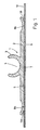
- the inventive contact element 1 is formed as an elongated contact rail of constant cross section and is preferably made of aluminum. It comprises a rectangular contact plate 2, which carries on a top side a centrally arranged guide 3, which forms a channel 4 for receiving a cooling or heating fluid-carrying tube. At the bottom, the contact plate forms a flat contact surface 5. At both longitudinal edges, close to the contact surface 5 via a rounded edge with a radius of e.g. 0.5 mm continuously flat edge strips 6a, b, which include the contact surface 5 at an angle of 150 ° and at the edge of the contact plate 2 at least 0.5mm, preferably at least 1mm above the plane of the contact surface 5 are. Angles between 120 ° and 160 ° are well suited. The edge strips could also be curved, e.g. slightly convex, with smooth transition to the contact surface. Preferably, they rise to the edge of the contact plate to the outside steadily and form no outwardly facing steps.
- the contact surface 5 is divided into a most of the same engaging adhesive surface, which is covered by an adhesive layer 7 and the adhesive layer. 7 free boundary strips 8a, b, which extend from the edge of the adhesive surface to the edge of the contact surface 5, where the edge strips 6a, b connect.
- the adhesive layer 7 connects the contact element 1 with a perforated plate 9. Their thickness is between 0.18 mm and 0.2 mm.
- the adhesive surface may also be slightly higher in relation to their environment, ie form the reason of a shallow depression in the contact surface.
- the perforated plate 9 carries a plurality of contact elements 1 arranged parallel to one another at a distance from one another.
- the region not covered by the contact surfaces 5 is covered by a nonwoven 10, an approximately 0.2 mm thick acoustic nonwoven having a sound-damping effect.
- the fleece 10 extends on both sides of the contact plate 2 at least to the outer edge of the boundary strips 8a, b, but it is advantageous if it is pulled up under the border strip 8a, b and possibly to the vicinity of the adhesive layer 7.
- the fleece 10 is preferably slightly thicker than the adhesive layer 7 and therefore slightly clamped under the boundary strip 8a, b and thus reliably held. It may reach to the edge of the adhesive layer 7, but this is not required.
- the position of the edge of the nonwoven 10 can vary by the width of the border strip 8a, b, without creating a disturbing uncovered strip on the upper side of the perforated plate 9.
- the contact elements 1 are first provided with an approximately 0.25 mm thick adhesive layer and then pressed against the top of the perforated plate 9, wherein the adhesive layer is compressed to the said thickness of 0.18 mm to 0.2 mm and, slightly extending laterally, covering the adhesive surface.
- the nonwoven 10 can be either in strips, which fit between the contact elements or in one piece, with cut strip-shaped openings whose width is slightly larger than that of the adhesive surface, with to the transverse edges of the openings subsequent cuts.
- the nonwoven is placed, wherein it is slightly arched between the contact elements 1 and the openings bounding the openings at the edges of the contact plates 2 are pending. Then, the edge areas of the web adjoining the openings are pressed by pressure on the same from above and stroking movements against the contact plate 2 under the edge strips 6a, b, of which they are further guided below the contact surface 5, to the web 10 between the contact elements 1 lies flat on the perforated plate 9, with the edges of the openings under the boundary strips 8a, b.
- the edge strips 6a, b allow in each case a problem-free insertion of the opening-limiting edges of the web under the contact surface. 5
Landscapes
- Engineering & Computer Science (AREA)
- Physics & Mathematics (AREA)
- Thermal Sciences (AREA)
- Chemical & Material Sciences (AREA)
- Combustion & Propulsion (AREA)
- Mechanical Engineering (AREA)
- General Engineering & Computer Science (AREA)
- Building Environments (AREA)
- Burglar Alarm Systems (AREA)
- Fixed Capacitors And Capacitor Manufacturing Machines (AREA)
- Thermistors And Varistors (AREA)
- Connector Housings Or Holding Contact Members (AREA)
Description
- Die Erfindung betrifft ein Kontaktelement gemäss dem Oberbegriff des Anspruchs 1 und ein Deckenelement, welches ein Kontaktelement umfasst. Deckenelemente dieser Art werden zur Klimatisierung von Räumen eingesetzt. Die Kontaktelemente dienen dabei zur Herstellung eines guten thermischen Kontakts zwischen von Kühl- oder Heizflüssigkeit durchflossenen Rohren und einer Lochplatte des Deckenelements, mit der sie verklebt sind.
- Aus der
US-4 635 710 A ist ein gattungsgemässes Kontaktelement bekannt, bei dem an die Kontaktfläche beidseits je ein gerundeter Randstreifen stetig anschliesst. Es ist jedoch nicht ersichtlich, dass die Kontaktfläche eine Kleberschicht vorgesehen wäre, schon gar nicht eine von den Randstreifen beabstandete. Ein das Kontaktelement umfassendes Deckenelement weist ausserdem ein Panel mit eingebogenen Randstreifen auf, welches auf das Kontaktelement aufgeschnappt ist, wobei die Randstreifen des elastischen Panels die Ränder des Kontaktelements umgreifen. Zwischen dem Panel und dem Kontaktelement kann dabei ein wärmeleitender Füllstoff, bei dem es sich auch um einen Klebstoff handeln kann, angeordnet sein, der die Kontaktfläche des Kontaktelements und dessen Randstreifen vollständig bedeckt. Das Kontaktelement ist nicht unmittelbar zur Verbindung mit einer Lochplatte geeignet, deren Oberseite auch von der Kontaktfläche freie, von einem Vlies bedeckte Bereiche aufweist, sondern ist lediglich als Träger eines einzelnen aufschnappbaren Panels vorgesehen. - Es sind ausserdem Kontaktelemente bekannt, bei denen die Kontaktfläche eben bis zum Rand der Kontaktplatte durchgeht und ganz oder teilweise eine von einer Kleberschicht bedeckte Klebefläche bildet. Daneben sind (s. z.B.
EP-0 769 659 A1 ) ähnliche Kontaktelemente bekannt, bei denen die Kontaktfläche zur Aufnahme einer Kleberschicht mittige oder am Rand liegende, durch eine Stufe abgesetzte, geringfügig höher als ihr verbleibender Teil angeordnete, aber zu demselben parallele Klebeflächen umfasst. In allen Fällen erstreckt sich die Kontaktfläche jeweils eben bis zum Rand der Kontaktplatte, wo dann rechtwinklig eine senkrechte Seitenfläche der Kontaktplatte anschliesst. - Zur Herstellung eines Deckenelements werden die Kontaktelemente direkt auf die Lochplatte geklebt. Das Vlies wird so ausgeschnitten, dass es die von den Kontaktflächen bedeckten Bereiche der Lochplatte freilässt und dann auf die Deckenplatte aufgelegt und punktuell mit ihr verklebt. Es ist jedoch schwierig, die Kontaktelemente so genau auf der Lochplatte anzuordnen und das Vlies so genau zuzuschneiden, dass es überall genau bis zu den Rändern der Kontaktflächen reicht. Oft bleiben dort schmale Streifen frei, an denen dann Luft durch die Lochplatte zirkuliert. Dies führt jedoch meist rasch zu einer Verschmutzung der Decke in diesem Bereich, was aus ästhetischen Gründen unerwünscht ist.
- Der Erfindung liegt die Aufgabe zu Grunde, ein Kontaktelement anzugeben, welches direkt mit der Lochplatte verklebt werden kann, so dass ein zuverlässiger mechanischer und thermischer Kontakt mit derselben gewährleistet ist, welches aber gleichzeitig gestattet, die Lochplatte derart mit Vlies zu bedecken, dass keine Bereiche frei bleiben und die Abdeckung der Lochplatte an den Rändern der Kontaktfläche jeweils lückenlos ist. Ausserdem soll ein entsprechendes Deckenelement angegeben werden.
- Diese Aufgaben werden durch die Merkmale im kennzeichnenenden Teil des Anspruchs 1 bzw. durch die Merkmale des Anspruchs 7 gelöst. Die Erfindung erlaubt es, den nicht von den Kontaktflächen bedeckten Bereich lückenlos abzudecken, ohne dass schwer erfüllbare Anforderungen an die Präzision der Fertigung gestellt werden müssten. Ein weiterer Vorteil der Erfindung liegt darin, dass das Vlies zuverlässig an der Lochplatte fixiert ist.
- Im folgenden wird die Erfindung anhand einer Figur, welche lediglich ein Ausführungsbeispiel darstellt, näher erläutert.
- Fig. 1
- zeigt einen Querschnitt durch einen Teil eines erfindungsgemässen Deckenelements.
- Das erfindungsgemässe Kontaktelement 1 ist als längliche Kontaktschiene gleichbleibenden Querschnitts ausgebildet und besteht vorzugsweise aus Aluminium. Es umfasst eine rechteckige Kontaktplatte 2, welche an einer Oberseite eine mittig angeordnete Führung 3 trägt, welche einen Kanal 4 zur Aufnahme eines Kühl- oder Heizflüssigkeit führenden Rohres bildet. An der Unterseite bildet die Kontaktplatte eine ebene Kontaktfläche 5. An beiden Längsrändern schliessen an die Kontaktfläche 5 über eine gerundete Kante mit einem Radius von z.B. 0,5mm stufenlos ebene Randstreifen 6a,b an, welche mit der Kontaktfläche 5 einen Winkel von 150° einschliessen und am Rand der Kontaktplatte 2 mindestens 0,5mm, vorzugsweise mindestens 1mm über der Ebene der Kontaktfläche 5 liegen. Winkel zwischen 120° und 160° sind gut geeignet. Die Randstreifen könnten auch gekrümmt, z.B. leicht konvex sein, mit glattem Uebergang zur Kontaktfläche. Vorzugsweise steigen sie bis zum Rand der Kontaktplatte nach aussen stetig an und bilden keine nach aussen weisenden Stufen.
- Die Kontaktfläche 5 zerfällt in eine den grössten Teil derselben einnehmende Klebefläche, welche von einer Kleberschicht 7 bedeckt ist und von der Kleberschicht 7 freie Grenzstreifen 8a,b, welche sich vom Rand der Klebefläche bis zum Rand der Kontaktfläche 5 erstrecken, wo die Randstreifen 6a,b anschliessen. Die Kleberschicht 7 verbindet das Kontaktelement 1 mit einer Lochplatte 9. Ihre Dicke beträgt zwischen 0,18mm und 0,2mm. Die Klebefläche kann auch gegenüber ihrer Umgebung geringfügig höher liegen, d.h. den Grund einer flachen Vertiefung in der Kontaktfläche bilden.
- Die Lochplatte 9 trägt mehrere parallel mit Abstand nebeneinander angeordnete Kontaktelemente 1. Der nicht von den Kontaktflächen 5 derselben bedeckte Bereich ist von einem Vlies 10, einem etwa 0,2mm dicken Akustikvlies mit lärmdämpfender Wirkung, bedeckt. Das Vlies 10 reicht beidseits der Kontaktplatte 2 mindestens bis zum äusseren Rand der Grenzstreifen 8a,b, doch ist es von Vorteil, wenn es bis unter die Grenzstreifen 8a,b und möglichst bis in die Nähe der Kleberschicht 7 gezogen ist. Das Vlies 10 ist vorzugsweise geringfügig dicker als die Kleberschicht 7 und daher unter den Grenzstreifen 8a,b leicht geklemmt und damit zuverlässig festgehalten. Es kann bis zum Rand der Kleberschicht 7 reichen, doch ist dies nicht erforderlich. Die Lage des Randes des Vlieses 10 kann um die Breite des Grenzstreifens 8a;b schwanken, ohne dass ein störender unbedeckter Streifen an der Oberseite der Lochplatte 9 entstünde.
- Zur Herstellung des erfindungsgemässen Deckenelements werden die Kontaktelemente 1 zuerst mit einer ca. 0,25mm dicken Kleberschicht versehen und dann gegen die Oberseite der Lochplatte 9 gepresst, wobei die Kleberschicht auf die besagte Dicke von 0,18mm bis 0,2mm komprimiert wird und, sich seitlich geringfügig ausdehnend, die Klebefläche bedeckt. Das Vlies 10 kann entweder in Streifen vorliegen, die zwischen die Kontaktelemente passen oder einstückig, mit ausgeschnittenen streifenförmigen Oeffnungen, deren Breite jeweils geringfügig grösser ist als die der Klebfläche, mit an die die Querränder der Oeffnungen anschliessenden Schnitten.
- Das Vlies wird aufgelegt, wobei es zwischen den Kontaktelementen 1 etwas aufgewölbt ist und die die Oeffnungen begrenzenden Ränder an den Rändern der Kontaktplatten 2 anstehen. Dann werden die an die Oeffnungen anschliessenden Randbereiche des Vlieses durch Druck auf dasselbe von oben und streichende Bewegungen gegen die Kontaktplatte 2 unter die Randstreifen 6a;b gedrückt, von denen sie im weiteren unter die Kontaktfläche 5 geführt werden, bis das Vlies 10 zwischen den Kontaktelementen 1 flach auf der Lochplatte 9 liegt, mit den Rändern der Oeffnungen unter den Grenzstreifen 8a;b. Die Randstreifen 6a,b erlauben dabei jeweils ein problemloses Einschieben der die Oeffnung begrenzenden Ränder des Vlieses unter die Kontaktfläche 5.
-
- 1
- Kontaktelement
- 2
- Kontaktplatte
- 3
- Führung
- 4
- Kanal
- 5
- Kontaktfläche
- 6a,b
- Randstreifen
- 7
- Kleberschicht
- 8a,b
- Grenzstreifen
- 9
- Lochplatte
- 10
- Vlies
Claims (9)
- Kontaktelement mit einer Kontaktplatte (2), welche an einer Unterseite eine ebene Kontaktfläche (5) aufweist, an welche an einander gegenüberliegenden Rändern jeweils nach aussen ansteigende Randstreifen (6a, 6b) stufenlos anschliessen und mit mindestens einer an der Oberseite der Kontaktplatte (2) angeordneten, sich im wesentlichen über ihre Länge erstreckenden Führung (3) für ein Rohr, dadurch gekennzeichnet, dass die Kontaktfläche (5) eine Kleberschicht (7) trägt, welche von den Randstreifen (6a, 6b) beabstandet ist.
- Kontaktelement nach Anspruch 1, dadurch gekennzeichnet, dass die Kleberschicht (7) annähernd die ganze Kontaktfläche (5) bedeckt, wobei an die Randstreifen (6a, 6b) anschliessende Grenzstreifen (8a, 8b) derselben frei bleiben.
- Kontaktelement nach Anspruch 1 oder 2, dadurch gekennzeichnet, dass die Randstreifen (6a, 6b) sich jeweils stufenlos bis zu einem Aussenrand der Kontaktplatte (2) erstrecken und dort, vorzugsweise um mindestens 0,5mm, über der Ebene der Kontaktfläche (5) liegen.
- Kontaktelement nach einem der Ansprüche 1 bis 3, dadurch gekennzeichnet, dass die Randstreifen (6a, 6b) eben sind und mit der Kontaktfläche (5) einen stumpfen Winkel, der vorzugsweise zwischen 120° und 160° liegt, einschliessen.
- Kontaktelement nach einem der Ansprüche 1 bis 4, dadurch gekennzeichnet, dass die Kontaktfläche (5) rechteckig ist und die Randstreifen (6a, 6b) an ihre Längsränder anschliessen.
- Kontaktelement nach Anspruch 5, dadurch gekennzeichnet, dass sein Querschnitt über seine Länge im wesentlichen konstant ist.
- Deckenelement mit mindestens einem Kontaktelement (1) nach einem der Ansprüche 1 bis 6 sowie mit einer Lochplatte (9), mit deren Oberseite eine Klebefläche des mindestens einen Kontaktelements (1), welche sich über einen Teil der Kontaktfläche (5), der an die Randstreifen (6a, 6b) anschliessende Grenzstreifen (8a, 8b) frei lässt, erstreckt, mittels der Kleberschicht (7) verklebt ist sowie mit einem Vlies (10), welches vom mindestens einen Kontaktelement (1) freie Bereiche der Oberseite der Lochplatte (9) bedeckt, wobei die Klebefläche ausgespart ist, das Vlies (10) jedoch überall mindestens bis zum Rand der Kontaktfläche (5) und vorzugsweise in die Grenzstreifen (8a, 8b) hinein reicht.
- Deckenelement nach Anspruch 7, dadurch gekennzeichnet, dass die Dicke des Vlieses (10) geringfügig grösser ist als die der Kleberschicht (7), so dass unter den Grenzstreifen (8a, 8b) liegende Teile desselben leicht geklemmt sind.
- Deckenelement nach Anspruch 7 oder 8, dadurch gekennzeichnet, dass das Vlies (10) die nicht von der Kontaktfläche (5) des mindestens einen Kontaktelements (1) bedeckten Teile der Oberseite der Lochplatte (9) lückenlos bedeckt.
Priority Applications (3)
| Application Number | Priority Date | Filing Date | Title |
|---|---|---|---|
| DE502004007273T DE502004007273D1 (de) | 2004-01-21 | 2004-01-21 | Kontaktelement und Deckenelement |
| AT04405038T ATE397192T1 (de) | 2004-01-21 | 2004-01-21 | Kontaktelement und deckenelement |
| EP04405038A EP1557614B1 (de) | 2004-01-21 | 2004-01-21 | Kontaktelement und Deckenelement |
Applications Claiming Priority (1)
| Application Number | Priority Date | Filing Date | Title |
|---|---|---|---|
| EP04405038A EP1557614B1 (de) | 2004-01-21 | 2004-01-21 | Kontaktelement und Deckenelement |
Publications (2)
| Publication Number | Publication Date |
|---|---|
| EP1557614A1 EP1557614A1 (de) | 2005-07-27 |
| EP1557614B1 true EP1557614B1 (de) | 2008-05-28 |
Family
ID=34626559
Family Applications (1)
| Application Number | Title | Priority Date | Filing Date |
|---|---|---|---|
| EP04405038A Expired - Lifetime EP1557614B1 (de) | 2004-01-21 | 2004-01-21 | Kontaktelement und Deckenelement |
Country Status (3)
| Country | Link |
|---|---|
| EP (1) | EP1557614B1 (de) |
| AT (1) | ATE397192T1 (de) |
| DE (1) | DE502004007273D1 (de) |
Families Citing this family (1)
| Publication number | Priority date | Publication date | Assignee | Title |
|---|---|---|---|---|
| FR2973405A1 (fr) * | 2011-03-30 | 2012-10-05 | Philippe Bergey | Rail thermique pour dalle chauffante |
Family Cites Families (5)
| Publication number | Priority date | Publication date | Assignee | Title |
|---|---|---|---|---|
| FR1306680A (fr) * | 1961-09-05 | 1962-10-19 | Perfectionnements apportés aux ensembles du genre des planchers chauffants | |
| FR86576E (fr) * | 1964-10-14 | 1966-03-04 | Nessi Freres & Cie | Plaques préfabriquées pour plafonds chauffants et rafraîchissants |
| DE1946011A1 (de) * | 1969-09-11 | 1971-03-25 | Welz Hans Joachim Dipl Ing | Deckenstrahlungsheizung bzw. -kuehlung |
| US4635710A (en) * | 1984-02-02 | 1987-01-13 | William Shelley | Linear radiant ceiling panel |
| DE29702534U1 (de) * | 1997-02-13 | 1998-06-25 | Tever Technik Vertriebs- und Beteiligungs-GmbH & Co. Beratungs KG, 83052 Bruckmühl | Heizpaneel |
-
2004
- 2004-01-21 EP EP04405038A patent/EP1557614B1/de not_active Expired - Lifetime
- 2004-01-21 AT AT04405038T patent/ATE397192T1/de not_active IP Right Cessation
- 2004-01-21 DE DE502004007273T patent/DE502004007273D1/de not_active Expired - Lifetime
Also Published As
| Publication number | Publication date |
|---|---|
| EP1557614A1 (de) | 2005-07-27 |
| DE502004007273D1 (de) | 2008-07-10 |
| ATE397192T1 (de) | 2008-06-15 |
Similar Documents
| Publication | Publication Date | Title |
|---|---|---|
| EP0769659B1 (de) | Kontaktelement und Deckenelement für eine Heiz- und Kühldecke | |
| EP0764818B1 (de) | Kontaktelement und Deckenelement für eine Heiz- und Kühldecke | |
| EP0662547B1 (de) | Deckenelement für eine Heiz- und Kühldecke | |
| DE2725024A1 (de) | Fenstereinheit fuer backofentuer | |
| DD255980A5 (de) | Vakuum-sonnenkollektor | |
| EP1078205B1 (de) | Luftkühlelement, verfahren zu seinem betrieb sowie luftkühlanordnung | |
| CH632049A5 (de) | Zur stuetzung eines randes eines plattenfoermigen koerpers, insbesondere einer isolierglastafel, bestimmtes element. | |
| EP3839370A1 (de) | Vorrichtung zum befestigen von solarpaneelen | |
| DE10196810T5 (de) | Verbundkonstruktionsteil, insbesondere zur Herstellung von Verkleidungs- und Wandkonstruktionen von Gebäuden | |
| DE102005056439A1 (de) | Profilleiste zur Verwendung im Innenausbau sowie Bausatz einschließlich einer solchen Profilleiste | |
| DE202005018137U1 (de) | Dacheindeckung | |
| EP1557614A1 (de) | Kontaktelement und Deckenelement | |
| DE10257977A1 (de) | Raumbegrenzungs-Paneel | |
| DE2009547A1 (de) | Heizelement | |
| EP1777469A1 (de) | Kühlelement | |
| EP2995871A1 (de) | Deckenelement sowie heiz- und kühldecke | |
| EP1882143B1 (de) | Einbau-haushaltsgerät mit einer justierschiene | |
| DE4441296C1 (de) | Universallüfter mit plissierten Seitenteilen in gespritzter Ausführung | |
| EP3309314A1 (de) | Deckenelement sowie heiz- und kühldecke | |
| DE102017102536A1 (de) | Halterung zur Befestigung einer Verkleidung an einer Gebäudewand oder -decke | |
| AT413719B (de) | Vorrichtung für die in-dach-verbindung von wenigstens zwei plattenförmigen bauteilen auf einem schrägdach | |
| WO2015117706A1 (de) | Kühlkörper | |
| DE9412349U1 (de) | Kühldecke | |
| DE69924730T3 (de) | Tür, Türpaneel und Herstellungsverfahren dafür | |
| DE102017006751A1 (de) | Verbundbauteil, Zusammenbau mit einem solchen Verbundbauteil, und Fahrzeug mit einem solchen Zusammenbau |
Legal Events
| Date | Code | Title | Description |
|---|---|---|---|
| PUAI | Public reference made under article 153(3) epc to a published international application that has entered the european phase |
Free format text: ORIGINAL CODE: 0009012 |
|
| AK | Designated contracting states |
Kind code of ref document: A1 Designated state(s): AT BE BG CH CY CZ DE DK EE ES FI FR GB GR HU IE IT LI LU MC NL PT RO SE SI SK TR |
|
| AX | Request for extension of the european patent |
Extension state: AL LT LV MK |
|
| 17P | Request for examination filed |
Effective date: 20060121 |
|
| AKX | Designation fees paid |
Designated state(s): AT CH DE GB LI NL |
|
| 17Q | First examination report despatched |
Effective date: 20070604 |
|
| GRAP | Despatch of communication of intention to grant a patent |
Free format text: ORIGINAL CODE: EPIDOSNIGR1 |
|
| RAP1 | Party data changed (applicant data changed or rights of an application transferred) |
Owner name: MWH BARCOL-AIR AG |
|
| GRAS | Grant fee paid |
Free format text: ORIGINAL CODE: EPIDOSNIGR3 |
|
| GRAA | (expected) grant |
Free format text: ORIGINAL CODE: 0009210 |
|
| AK | Designated contracting states |
Kind code of ref document: B1 Designated state(s): AT CH DE GB LI NL |
|
| REG | Reference to a national code |
Ref country code: GB Ref legal event code: FG4D Free format text: NOT ENGLISH |
|
| REG | Reference to a national code |
Ref country code: CH Ref legal event code: EP |
|
| REF | Corresponds to: |
Ref document number: 502004007273 Country of ref document: DE Date of ref document: 20080710 Kind code of ref document: P |
|
| REG | Reference to a national code |
Ref country code: CH Ref legal event code: NV Representative=s name: ZIMMERLI, WAGNER & PARTNER AG |
|
| PLBE | No opposition filed within time limit |
Free format text: ORIGINAL CODE: 0009261 |
|
| STAA | Information on the status of an ep patent application or granted ep patent |
Free format text: STATUS: NO OPPOSITION FILED WITHIN TIME LIMIT |
|
| 26N | No opposition filed |
Effective date: 20090303 |
|
| REG | Reference to a national code |
Ref country code: CH Ref legal event code: PFA Owner name: MWH BARCOL-AIR AG Free format text: MWH BARCOL-AIR AG#GRUNDSTRASSE 10B#8712 STAEFA (CH) -TRANSFER TO- MWH BARCOL-AIR AG#GRUNDSTRASSE 10B#8712 STAEFA (CH) |
|
| PGFP | Annual fee paid to national office [announced via postgrant information from national office to epo] |
Ref country code: AT Payment date: 20100113 Year of fee payment: 7 Ref country code: DE Payment date: 20100114 Year of fee payment: 7 Ref country code: GB Payment date: 20100120 Year of fee payment: 7 |
|
| PGFP | Annual fee paid to national office [announced via postgrant information from national office to epo] |
Ref country code: NL Payment date: 20100101 Year of fee payment: 7 |
|
| REG | Reference to a national code |
Ref country code: NL Ref legal event code: V1 Effective date: 20110801 |
|
| GBPC | Gb: european patent ceased through non-payment of renewal fee |
Effective date: 20110121 |
|
| PG25 | Lapsed in a contracting state [announced via postgrant information from national office to epo] |
Ref country code: AT Free format text: LAPSE BECAUSE OF NON-PAYMENT OF DUE FEES Effective date: 20110121 Ref country code: GB Free format text: LAPSE BECAUSE OF NON-PAYMENT OF DUE FEES Effective date: 20110121 |
|
| REG | Reference to a national code |
Ref country code: DE Ref legal event code: R119 Ref document number: 502004007273 Country of ref document: DE Effective date: 20110802 |
|
| PG25 | Lapsed in a contracting state [announced via postgrant information from national office to epo] |
Ref country code: NL Free format text: LAPSE BECAUSE OF NON-PAYMENT OF DUE FEES Effective date: 20110801 |
|
| PGFP | Annual fee paid to national office [announced via postgrant information from national office to epo] |
Ref country code: CH Payment date: 20130129 Year of fee payment: 10 |
|
| PG25 | Lapsed in a contracting state [announced via postgrant information from national office to epo] |
Ref country code: DE Free format text: LAPSE BECAUSE OF NON-PAYMENT OF DUE FEES Effective date: 20110802 |
|
| REG | Reference to a national code |
Ref country code: CH Ref legal event code: NV Representative=s name: WAGNER PATENT AG, CH |
|
| REG | Reference to a national code |
Ref country code: CH Ref legal event code: PL |
|
| PG25 | Lapsed in a contracting state [announced via postgrant information from national office to epo] |
Ref country code: LI Free format text: LAPSE BECAUSE OF NON-PAYMENT OF DUE FEES Effective date: 20140131 Ref country code: CH Free format text: LAPSE BECAUSE OF NON-PAYMENT OF DUE FEES Effective date: 20140131 |