EP1557588B1 - Load transfer detection device through breakable shear pin - Google Patents
Load transfer detection device through breakable shear pin Download PDFInfo
- Publication number
- EP1557588B1 EP1557588B1 EP05290104A EP05290104A EP1557588B1 EP 1557588 B1 EP1557588 B1 EP 1557588B1 EP 05290104 A EP05290104 A EP 05290104A EP 05290104 A EP05290104 A EP 05290104A EP 1557588 B1 EP1557588 B1 EP 1557588B1
- Authority
- EP
- European Patent Office
- Prior art keywords
- pin
- sensors
- lower plate
- upper plate
- spacing
- Prior art date
- Legal status (The legal status is an assumption and is not a legal conclusion. Google has not performed a legal analysis and makes no representation as to the accuracy of the status listed.)
- Expired - Fee Related
Links
- 238000001514 detection method Methods 0.000 title claims abstract description 42
- 230000000007 visual effect Effects 0.000 claims description 6
- 230000005355 Hall effect Effects 0.000 claims description 2
- 230000002093 peripheral effect Effects 0.000 claims description 2
- 238000005096 rolling process Methods 0.000 claims description 2
- 238000010008 shearing Methods 0.000 claims 3
- 230000001939 inductive effect Effects 0.000 claims 1
- 238000012806 monitoring device Methods 0.000 abstract description 6
- 238000012795 verification Methods 0.000 abstract description 3
- 230000001788 irregular Effects 0.000 abstract description 2
- 230000003213 activating effect Effects 0.000 abstract 1
- 241000920340 Pion Species 0.000 description 5
- 230000002159 abnormal effect Effects 0.000 description 1
- 230000005540 biological transmission Effects 0.000 description 1
- 239000003086 colorant Substances 0.000 description 1
- 230000003247 decreasing effect Effects 0.000 description 1
- 230000002950 deficient Effects 0.000 description 1
- 230000000694 effects Effects 0.000 description 1
- 238000005516 engineering process Methods 0.000 description 1
- 230000006698 induction Effects 0.000 description 1
- 210000003127 knee Anatomy 0.000 description 1
- 230000003472 neutralizing effect Effects 0.000 description 1
- 210000000056 organ Anatomy 0.000 description 1
- 230000000149 penetrating effect Effects 0.000 description 1
- 230000000284 resting effect Effects 0.000 description 1
- 230000000717 retained effect Effects 0.000 description 1
- 238000000926 separation method Methods 0.000 description 1
Images

Classifications
-
- F—MECHANICAL ENGINEERING; LIGHTING; HEATING; WEAPONS; BLASTING
- F16—ENGINEERING ELEMENTS AND UNITS; GENERAL MEASURES FOR PRODUCING AND MAINTAINING EFFECTIVE FUNCTIONING OF MACHINES OR INSTALLATIONS; THERMAL INSULATION IN GENERAL
- F16H—GEARING
- F16H25/00—Gearings comprising primarily only cams, cam-followers and screw-and-nut mechanisms
- F16H25/18—Gearings comprising primarily only cams, cam-followers and screw-and-nut mechanisms for conveying or interconverting oscillating or reciprocating motions
- F16H25/20—Screw mechanisms
- F16H25/24—Elements essential to such mechanisms, e.g. screws, nuts
- F16H25/2472—Safety nuts
-
- B—PERFORMING OPERATIONS; TRANSPORTING
- B64—AIRCRAFT; AVIATION; COSMONAUTICS
- B64C—AEROPLANES; HELICOPTERS
- B64C13/00—Control systems or transmitting systems for actuating flying-control surfaces, lift-increasing flaps, air brakes, or spoilers
- B64C13/24—Transmitting means
- B64C13/26—Transmitting means without power amplification or where power amplification is irrelevant
- B64C13/28—Transmitting means without power amplification or where power amplification is irrelevant mechanical
- B64C13/341—Transmitting means without power amplification or where power amplification is irrelevant mechanical having duplication or stand-by provisions
-
- F—MECHANICAL ENGINEERING; LIGHTING; HEATING; WEAPONS; BLASTING
- F16—ENGINEERING ELEMENTS AND UNITS; GENERAL MEASURES FOR PRODUCING AND MAINTAINING EFFECTIVE FUNCTIONING OF MACHINES OR INSTALLATIONS; THERMAL INSULATION IN GENERAL
- F16H—GEARING
- F16H57/00—General details of gearing
-
- F—MECHANICAL ENGINEERING; LIGHTING; HEATING; WEAPONS; BLASTING
- F16—ENGINEERING ELEMENTS AND UNITS; GENERAL MEASURES FOR PRODUCING AND MAINTAINING EFFECTIVE FUNCTIONING OF MACHINES OR INSTALLATIONS; THERMAL INSULATION IN GENERAL
- F16H—GEARING
- F16H57/00—General details of gearing
- F16H57/01—Monitoring wear or stress of gearing elements, e.g. for triggering maintenance
- F16H2057/018—Detection of mechanical transmission failures
Definitions
- the invention relates to so-called "fail-safe" screw jacks, that is to say screw jacks whose aircraft and structure fasteners are doubled in order to increase the level of safety.
- Screw jack systems for actuating an aircraft movable member generally have two fasteners: a so-called aircraft fastener attachment by which the screw is connected to the structure of the aircraft and a fastener said fastening structure by which the screw is connected via a nut to the movable member to be actuated.
- the links vis-aircraft (aircraft attachment) and screw-movable member (attachment structure) are provided respectively by so-called primary channels.
- the connection is then taken by an emergency route, called secondary track.
- the invention more particularly relates to systems for detecting the failure of a fastener, during a charge transfer from the primary to the secondary path.
- the invention thus relates to the detection of the transfer of load from the primary nut to the secondary nut.
- the invention is applicable to screw jacks, for example when these jacks are used for the orientation of an aircraft adjustable horizontal plane (PHR).
- PHR aircraft adjustable horizontal plane
- a safe fail-safe device presents the danger that an operation resting only on the secondary path (for example the secondary nut in the case of the fastener structure), after failure of the primary path (the nut primary), is not detected. The device then no longer has its extra level of security, and thereby loses its initial interest.
- seizure can often not appear.
- the forces during the flight may for example not be so important that the secondary nut is caught in contact with the screw.
- the verifiability can generally make it easy to ensure the good operating condition of the load transfer detection system, and in particular that the parts constituting it are not seized or that the electrical connection through the pion is not not defective.
- the object of the invention is thus to provide, both at the level of the aircraft fastener and the structure fastener, a system for detecting the transfer of charge on the secondary track that is verifiable.
- the document EP 1283384 has an actuating system according to the preamble of claim 1.
- the invention proposes, according to a first aspect, a device for detecting the transfer of the load of a mobile actuator actuator screw from a primary track to a secondary track, as defined in claim 1.
- the operating state of the device according to the invention can be regularly checked, the false alarms (detection of a non-existent fault, for example due to a faulty electrical connection or a bad positioning of the parts) are avoided and the The level of security offered by the device is increased (a failure will actually be detected, for example because seizure of the parts neutralizing the detection can be detected).
- the invention provides a movable member actuating cylinder comprising such a detection device at its plane attachment.
- the invention provides a movable member actuating cylinder comprising such a detection device at its structure attachment.
- a screw jack system for actuating an aircraft movable member comprises two fasteners: an aircraft fastener through which the screw is linked to the structure of the aircraft (fuselage) and a fastening structure by which the screw is connected via a nut to the movable member to be actuated.
- Each of these fasteners has a secondary backup channel, able to resume the load of the screw in case of failure of the primary path.
- the detection device may be used to detect the failure of the primary track of one or other of the aircraft and structure fasteners.
- the primary nut here ball
- PHR adjustable horizontal plane
- each of the primary and secondary nuts has a connection of its own with the actuated member.
- the transfer of load on the secondary nut is then done by loading the own connection of the secondary nut and unloading the own connection of the primary nut.
- the secondary nut has, next to the pitch of the screw, a clearance sufficient to not be loaded in the case of normal operation where the primary nut takes charge.
- the secondary track resumes the load via the secondary nut.
- the secondary nut is then mechanically placed on the path of the charges between the structure of the aircraft and the movable member, and comes into contact with the screw.
- the device comprises a rupturable pin 1 mounted at the level of the structural fastener of a screw jack system, so as to come across a room linked to the secondary road and another room linked to an organ attached to the primary road.
- the pin 1 is substantially cylindrical and extends longitudinally along its main axis 14.
- journal 2 of the secondary nut (not shown).
- a support 3 Said other part connected to an integral member of the primary track is here a support 3, a lower portion is secured to a transfer plate 5 ensuring the proper connection of the primary nut.
- Said transfer plate 5 surrounds with a small clearance (illustrated by the arrows 4) the pin 2 of the secondary nut.
- the journal 2 has on one external face a reservation into which one of the ends (lower end 10) of the pin 1, the reservation whose peripheral edge is covered by the lower part of said support 3 secured to the transfer plate 5.
- the pin 1 thus has a contact zone with the lower part of said support 3, this zone of the pin 1 advantageously having a section to be broken 6 that can be sheared during a relative movement between the support 3 and the pin 1.
- the lower end 10 of the pin 1 has a section whose diameter is greater than that of the section of the portion of the pin passing through the support 3, so that said lower end of the pin can be retained in the pin 2 by abutting on the support 3.
- the support 3 also extends along the main axis 14 of the pin so as to form a cylindrical tube surrounding the detection device according to the invention.
- Said tube advantageously comprises a cover 9, in particular making it possible to maintain the mounting of the device according to the invention, as well as its protection vis-à-vis the external environment.
- the pin 1 has, at its end opposite to that penetrating the reservation of the pin 2, a circumferential protrusion (upper plate 7) that can be pushed from the lower part of the support 3, along the axis 14, by a first member of elastic return disposed between said upper plate 7 and the upper part of the support 3.
- said first elastic return member is a helical spring 8 surrounding the pin.
- a transfer of the load on the secondary path is accompanied by a relative movement (authorized by the game which has been reported) between the transfer plate 5 and the journal 2.
- the portion of the pin having the upper plate 7 is then spaced from the portion of the pin remaining in the pin 2 (lower end 10) in a translation movement along the axis 14.
- the pin 1 comprises, at the level of the zone which is surrounded by the support 3, a guide 11 making it possible to prevent "Burrs" due to the breaking of the pawn can come block the separation of the pawn in two parts.
- the detection device further comprises a lower plate 12 surrounding the pin 1, being interposed between the upper plate 7 of said pin 1 and the lower part of the support 3.
- the upper plate 7 and lower 12 and have faces facing one another.
- the lower plate 12 is connected to the lower part of the support 3 by a second elastic return member 13 adapted to bring the lower plate 12 to the upper plate 7, so that elements 14, 15 respectively connected to said upper plates 7 and lower 12 are in contact during normal operation of the jack system (when the primary channel is loaded).
- said elements 14, 15 connected to the trays 7, 12 may be spaced from each other by a predefined distance.
- said second elastic return member is a helical spring 13 surrounding the pin.
- the detection device comprises means for detecting the rupture of the pin 1 able to determine that said plates 12, 13 are separated (or at least a distance greater than the predefined distance separating them in normal operating mode).
- the rupture detection means may comprise at least one pair of sensors, each of the sensors 14, 15 of a pair being disposed on one respectively of the plates 7, 12 so as to be two by two opposite .
- the means for detecting the rupture also comprise means (for example in the form of a monitoring device 16) able to determine whether the spacing of the sensors is normal or irregular.
- induction Hall effect sensors LVDT Linear Variable-Differential Transformer for Linear Variation Differential Transformer.
- the sensors 14, 15 are electrical contacts each connected by an electrical connection to the monitoring device 16.
- Said sensors thus provide electrical continuity when the plates are in contact with each other.
- the detection device also comprises means for verifying, without breaking the pin, the operation of said means for detecting the rupture.
- these verification means comprise a substantially cylindrical push button 17, guided along the axis 14, using the cover 9.
- One of the ends (upper end) of said knob 17 advantageously exceeds the cover 9 while the other end has a stop plate 18 disposed above the upper plate 7.
- Said stop plate 18 extends in the form of fingers 19 passing through openings made for this purpose in the upper plate 7 and coming into contact with the face of the lower plate 12 which is opposite the upper plate 7.
- the application of a force (for example by an operator) on the upper end of the push button 17 thus makes it possible to press the fingers 19 on the surface of the lower plate 12, by putting the second spring 13 under tension.
- the lower plate 12 can thus be pushed towards the lower part of the support 3, so that the plates 7, 12 are spaced from each other (see Figure 3).
- the sensors 14, 15 are then moved away from one another and the monitoring device 16 will then detect this abnormal gap.
- the device according to the invention makes it possible in particular to ensure that the sensors and the monitoring device function properly or that the parts are not seized.
- the verifiability of the device according to the invention makes it possible to increase the level of safety, thus decreasing the risk that a charge transfer on the secondary channel is not immediately detected.
- the button 17 has visual markers 20, 21 (for example strips of different colors) making it possible in particular to confirm a failure by a visual detection at the examination of said button 17.
- the button 17 is pushed back when the upper plate 7 abuts against the stop plate 18, causing this ci in its race, so that the two marks 21, 20 are then visible. The failure can then be visually detected.
- Such an aircraft fastener is generally provided via a primary fastening bar with the structure of the aircraft.
- the screw (not shown) of the cylinder system is thus rotatably connected with a sphere 40 of the tie bar.
- the sphere 40 rotates freely in a ball joint constituted by two half-ball joints (respectively a left half-ball 41 and half-right knee 42) integral with the secondary path.
- One of the ends of a shear cylinder 45 enters the sphere 40, said cylinder being consequently connected to a part integral with the primary track.
- a rolling member 44 is disposed at the area of contact between the sphere 40 and the cylinder 45 to neutralize the rotation of the sphere in the ball. In this way, the cylinder 45 has no relative movement vis-à-vis the elements related to the secondary path.
- the other end of the cylinder 45 comprises arms adapted to each accommodate the lower end of the pin of a detection device 50 according to the invention.
- At least one verifiable device is disposed at the level of the aircraft fastener so that its ruptible pin passes through a support 46, integral with the right half-ball 42 and therefore of the secondary track, and one of the arms said cylinder 45.
- two devices 50 according to the first aspect of the invention are used for the detection of a possible failure of the primary channel.
- the detection device is not solicited.
- the first spring will then move the upper plate of the lower plate, which will cause the detection of the transfer of load on the secondary track at the level of this aircraft attachment.
- the invention also relates to the actuator cylinders of movable member comprising a detection device such as that described in the previous description, at its aircraft attachment and its fastener structure.
Abstract
Description
L'invention concerne les vérins à vis dits "fail-safe", c'est-à-dire les vérins à vis dont les attaches avion et structure est doublée afin d'en augmenter le niveau de sécurité.The invention relates to so-called "fail-safe" screw jacks, that is to say screw jacks whose aircraft and structure fasteners are doubled in order to increase the level of safety.
Les systèmes de vérin à vis pour l'actionnement d'un organe mobile d'aéronef disposent généralement de deux attaches : une attache dite attache avion par laquelle la vis est liée à la structure de l'aéronef et une attache dite attache structure par laquelle la vis est liée via un écrou à l'organe mobile à actionner.Screw jack systems for actuating an aircraft movable member generally have two fasteners: a so-called aircraft fastener attachment by which the screw is connected to the structure of the aircraft and a fastener said fastening structure by which the screw is connected via a nut to the movable member to be actuated.
En mode de fonctionnement normal, les liaisons vis-aéronef (attache avion) et vis-organe mobile (attache structure) sont assurées respectivement par des voies dites primaires. En cas de défaillance de la voie primaire d'une attache, la liaison est alors reprise par une voie de secours, dite voie secondaire.In normal operating mode, the links vis-aircraft (aircraft attachment) and screw-movable member (attachment structure) are provided respectively by so-called primary channels. In case of failure of the primary channel of a fastener, the connection is then taken by an emergency route, called secondary track.
On connaît ainsi des systèmes de vérin comportant au niveau de l'attache structure, un niveau de sécurité supplémentaire en la présence d'un second écrou (écrou secondaire) qui, séparé de la vis par un léger jeu lors du fonctionnement normal, reprend la charge de l'écrou primaire en cas de défaillance de ce dernier.Thus known jack systems having at the structural fastener, an additional level of security in the presence of a second nut (secondary nut) which, separated from the screw by a slight clearance during normal operation, takes over the charging the primary nut in case of failure of the latter.
L'invention concerne plus particulièrement les systèmes de détection de la défaillance d'une attache, lors d'un transfert de charge de la voie primaire vers la voie secondaire.The invention more particularly relates to systems for detecting the failure of a fastener, during a charge transfer from the primary to the secondary path.
Dans le cas de l'attache structure, l'invention concerne ainsi la détection du transfert de charge de l'écrou primaire vers l'écrou secondaire.In the case of the structural fastener, the invention thus relates to the detection of the transfer of load from the primary nut to the secondary nut.
L'invention s'applique aux vérins à vis, par exemple quand ces vérins sont utilisés pour l'orientation d'un plan horizontal réglable (PHR) d'aéronef.The invention is applicable to screw jacks, for example when these jacks are used for the orientation of an aircraft adjustable horizontal plane (PHR).
Un dispositif « fail-safe » certes sécuritaire, présente le danger qu'un fonctionnement reposant seulement sur la voie secondaire (par exemple l'écrou secondaire dans le cas de l'attache structure), après défaillance de la voie primaire (l'écrou primaire), ne soit pas détecté. Le dispositif ne comporte alors plus son niveau de sécurité supplémentaire, et perd par là son intérêt initial.A safe fail-safe device presents the danger that an operation resting only on the secondary path (for example the secondary nut in the case of the fastener structure), after failure of the primary path (the nut primary), is not detected. The device then no longer has its extra level of security, and thereby loses its initial interest.
On cherche ici à signaler ce mode de fonctionnement le plus rapidement possible, afin d'éviter un mode de panne dormante.We seek here to report this mode of operation as quickly as possible, to avoid a dormant failure mode.
Typiquement, dans ce type de dispositif, on a adopté, pour l'attache structure, des écrous secondaires susceptibles de se gripper lorsque opérant avec la vis, de sorte qu'ils ne puissent continuer à remplir la fonction de transmission du mouvement.Typically, in this type of device, we have adopted, for the fastener structure, secondary nuts that can seize when operating with the screw, so that they can continue to perform the function of transmitting the movement.
Toutefois, le grippage risque souvent de ne pas apparaître. Les efforts durant le vol peuvent par exemple ne pas être assez importants pour que l'écrou secondaire se grippe au contact de la vis.However, seizure can often not appear. The forces during the flight may for example not be so important that the secondary nut is caught in contact with the screw.
La demanderesse a proposé dans sa demande de
Si un tel système à pion ruptible permet la détection du transfert de la charge vers la voie secondaire suite à la défaillance de la voie primaire, il n'est pas vérifiable.If such a pawn system allows the detection of the transfer of the load to the secondary path following the failure of the primary path, it is not verifiable.
Or la vérifiabilité peut de manière générale permettre de s'assurer aisément du bon état de fonctionnement du système de détection de transfert de charge, et en particulier que les pièces le constituant ne sont pas grippées ou que la connexion électrique traversant le pion n'est pas défectueuse.Or the verifiability can generally make it easy to ensure the good operating condition of the load transfer detection system, and in particular that the parts constituting it are not seized or that the electrical connection through the pion is not not defective.
Le but de l'invention est ainsi de fournir, tant au niveau de l'attache avion que de l'attache structure, un système de détection du transfert de charge sur la voie secondaire qui soit vérifiable.The object of the invention is thus to provide, both at the level of the aircraft fastener and the structure fastener, a system for detecting the transfer of charge on the secondary track that is verifiable.
Le document
A cet effet, l'invention propose, selon un premier aspect, un dispositif de détection du transfert de la charge d'une vis de vérin d'actionnement d'organe mobile depuis une voie primaire vers une voie secondaire, tel que défini à la revendication 1.For this purpose, the invention proposes, according to a first aspect, a device for detecting the transfer of the load of a mobile actuator actuator screw from a primary track to a secondary track, as defined in
L'état de fonctionnement du dispositif selon l'invention pouvant être régulièrement vérifié, les fausses alertes (détection d'une panne inexistante, par exemple du fait d'une liaison électrique défectueuse ou d'un mauvais positionnement des pièces) sont évitées et le niveau de sécurité offert par le dispositif est accru (une défaillance sera effectivement détectée, par exemple du fait qu'un grippage des pièces neutralisant la détection peut être décelé).The operating state of the device according to the invention can be regularly checked, the false alarms (detection of a non-existent fault, for example due to a faulty electrical connection or a bad positioning of the parts) are avoided and the The level of security offered by the device is increased (a failure will actually be detected, for example because seizure of the parts neutralizing the detection can be detected).
Selon un autre aspect défini à la revendication 13, l'invention propose un vérin d'actionnement d'organe mobile comprenant un tel dispositif de détection au niveau de son attache avion.According to another aspect defined in
Selon encore un autre aspect défini à la revendication 17, l'invention propose un vérin d'actionnement d'organe mobile comprenant un tel dispositif de détection au niveau de son attache structure.According to yet another aspect defined in
D'autres buts, caractéristiques et avantages de l'invention apparaîtront à la lecture de la description détaillée qui va suivre, faite en référence aux figures annexées sur lesquelles :
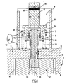
- la figure 1 est une vue en coupe d'un dispositif de détection selon l'invention, lors du fonctionnement normal d'un système de vérin à vis ;
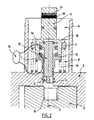
- la figure 2 est une vue en coupe d'un dispositif de détection selon l'invention, après rupture du pion suite à la défaillance de la voie primaire d'une attache (avion ou structure) du système de vérin à vis ;
- la figure 3 est une vue en coupe d'un dispositif de détection selon l'invention, lors de la vérification de son bon état de fonctionnement ;
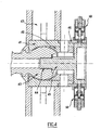
- la figure 4 est une vue en coupe illustrant la détection de la défaillance de la voie primaire de l'attache avion d'un système de vérin à vis pouvant être réalisée grâce au dispositif vérifiable selon l'invention.
- Figure 1 is a sectional view of a detection device according to the invention, during normal operation of a screw jack system;
- Figure 2 is a sectional view of a detection device according to the invention, after breakage of the pin following the failure of the primary path of a fastener (plane or structure) of the screw jack system;
- Figure 3 is a sectional view of a detection device according to the invention, during the verification of its good operating condition;
- Figure 4 is a sectional view illustrating the detection of the failure of the primary path of the aircraft fastener of a screw jack system that can be achieved through the verifiable device according to the invention.
Comme on l'a vu précédemment, un système de vérin à vis pour l'actionnement d'un organe mobile d'aéronef comporte deux attaches : une attache avion par laquelle la vis est liée à la structure de l'aéronef (fuselage) et une attache structure par laquelle la vis est liée via un écrou à l'organe mobile à actionner.As seen previously, a screw jack system for actuating an aircraft movable member comprises two fasteners: an aircraft fastener through which the screw is linked to the structure of the aircraft (fuselage) and a fastening structure by which the screw is connected via a nut to the movable member to be actuated.
Chacune de ces attaches dispose d'une voie secondaire de secours, apte à reprendre la charge de la vis en cas de défaillance de la voie primaire.Each of these fasteners has a secondary backup channel, able to resume the load of the screw in case of failure of the primary path.
Le dispositif de détection selon le premier aspect de l'invention peut être utilisé afin de détecter la défaillance de la voie primaire de l'une ou l'autre des attaches avion et structure.The detection device according to the first aspect of the invention may be used to detect the failure of the primary track of one or other of the aircraft and structure fasteners.
La description qui suit du dispositif selon l'invention concerne plus particulièrement l'attache structure. On comprendra cependant, notamment à l'examen de la figure 4, que celle-ci s'applique également à l'attache avion.The following description of the device according to the invention relates more particularly to the fastening structure. However, it will be understood, particularly on examining Figure 4, that it also applies to the aircraft attachment.
En fonctionnement normal, l'écrou primaire, ici à billes, est chargé et assure la transmission de la charge. L'écrou primaire transmet par exemple son mouvement à un plan horizontal réglable (PHR) d'un avion.In normal operation, the primary nut, here ball, is loaded and ensures the transmission of the load. The primary nut for example transmits its movement to an adjustable horizontal plane (PHR) of an aircraft.
Typiquement, on prévoit que chacun des écrous primaire et secondaire présente une liaison qui lui est propre avec l'organe actionné.Typically, it is expected that each of the primary and secondary nuts has a connection of its own with the actuated member.
Le transfert de charge sur l'écrou secondaire se fait alors par chargement de la liaison propre de l'écrou secondaire et déchargement de la liaison propre de l'écrou primaire.The transfer of load on the secondary nut is then done by loading the own connection of the secondary nut and unloading the own connection of the primary nut.
L'écrou secondaire présente, en regard du pas de la vis, un jeu suffisant pour ne pas être chargé dans le cas du fonctionnement normal où l'écrou primaire reprend la charge.The secondary nut has, next to the pitch of the screw, a clearance sufficient to not be loaded in the case of normal operation where the primary nut takes charge.
Suite à une défaillance de la voie primaire, la voie secondaire reprend la charge par l'intermédiaire de l'écrou secondaire. L'écrou secondaire est alors mécaniquement placé sur le trajet des charges entre la structure de l'avion et l'organe mobile, et entre en contact avec la vis.Following a failure of the primary track, the secondary track resumes the load via the secondary nut. The secondary nut is then mechanically placed on the path of the charges between the structure of the aircraft and the movable member, and comes into contact with the screw.
En référence aux figures 1, 2 et 3, le dispositif selon un mode de réalisation possible du premier aspect de l'invention comporte un pion ruptible 1 monté au niveau de l'attache structure d'un système de vérin à vis, de manière à venir traverser une pièce liée à la voie secondaire et une autre pièce liée à un organe solidaire de la voie primaire.With reference to FIGS. 1, 2 and 3, the device according to one possible embodiment of the first aspect of the invention comprises a
Le pion 1 est sensiblement cylindrique et s'étend longitudinalement le long de son axe principal 14.The
Ladite pièce liée à la voie secondaire est ici un tourillon 2 de l'écrou secondaire (non représenté).Said part connected to the secondary track is here a
Ladite autre pièce liée à un organe solidaire de la voie primaire est ici un support 3 dont une partie inférieure est solidaire d'une plaque de transfert 5 assurant la liaison propre de l'écrou primaire.Said other part connected to an integral member of the primary track is here a
Ladite plaque de transfert 5 entoure avec un faible jeu (illustré par les flèches 4) le tourillon 2 de l'écrou secondaire.Said
Le tourillon 2 présente sur une face externe une réservation dans laquelle pénètre l'une des extrémités (extrémité inférieure 10) du pion 1, réservation dont la bordure périphérique est recouverte par la partie inférieure dudit support 3 solidaire de la plaque de transfert 5.The
Le pion 1 présente ainsi une zone de contact avec la partie inférieure dudit support 3, cette zone du pion 1 présentant avantageusement une section à casser 6 pouvant être cisaillée lors d'un mouvement relatif entre le support 3 et le tourillon 1.The
L'extrémité inférieure 10 du pion 1 présente une section dont le diamètre est supérieur à celui de la section de la partie du pion traversant le support 3, de manière à ce que ladite extrémité inférieure du pion puisse être retenue dans le tourillon 2 en venant en butée sur le support 3.The
Le support 3 s'étend également le long de l'axe principal 14 du pion de manière à former un tube cylindrique entourant le dispositif de détection selon l'invention.The
Ledit tube comporte avantageusement un couvercle 9, permettant en particulier d'assurer le maintien du montage du dispositif selon l'invention, ainsi que sa protection vis-à-vis de l'environnement externe.Said tube advantageously comprises a
Le pion 1 présente, à son extrémité opposée à celle pénétrant dans la réservation du tourillon 2, une excroissance circonférentielle (plateau supérieur 7) pouvant être repoussée de la partie inférieure du support 3, le long de l'axe 14, par un premier organe de rappel élastique disposé entre ledit plateau supérieur 7 et la partie supérieure du support 3.The
De préférence, ledit premier organe de rappel élastique est un ressort hélicoïdal 8 entourant le pion.Preferably, said first elastic return member is a
Lors du fonctionnement normal du système de vérin, le plateau supérieur 7 est maintenu immobile, la force d'extension du premier ressort 8 étant neutralisée par l'épaulement présent à l'extrémité inférieure 10 du pion 1 qui vient en butée sur la partie inférieure du support 3.During normal operation of the jack system, the
Un transfert de la charge sur la voie secondaire s'accompagne d'un mouvement relatif (autorisé par le jeu dont il a été fait état) entre la plaque de transfert 5 et le tourillon 2.A transfer of the load on the secondary path is accompanied by a relative movement (authorized by the game which has been reported) between the
Ce mouvement relatif entraîne un cisaillement entre les pièces traversées par le pion 1, et donc une rupture du pion 1 au niveau de ladite section 6 (cf. figure 2).This relative movement causes shear between the parts traversed by the
Sous l'action du premier ressort 8, la partie du pion comportant le plateau supérieur 7 est alors écartée de la partie du pion restant dans le tourillon 2 (extrémité inférieure 10) selon un mouvement de translation le long de l'axe 14.Under the action of the
De manière préférentielle, le pion 1 comporte, au niveau de la zone qui est entourée par le support 3, un guidage 11 permettant d'éviter que des « bavures » dues à la rupture du pion puissent venir bloquer la séparation du pion en deux parties.Preferably, the
Le dispositif de détection selon un mode de réalisation possible de l'invention comporte en outre un plateau inférieur 12 venant entourer le pion 1, en étant intercalé entre le plateau supérieur 7 dudit pion 1 et la partie inférieure du support 3.The detection device according to a possible embodiment of the invention further comprises a
Les plateaux supérieur 7 et inférieur 12 présentent ainsi des faces en regard l'une de l'autre.The
Le plateau inférieur 12 est relié à la partie inférieure du support 3 par un deuxième organe de rappel élastique 13 adapté pour amener le plateau inférieur 12 vers le plateau supérieur 7, de sorte que des éléments 14, 15 liés respectivement auxdits plateaux supérieur 7 et inférieur 12 soient en contact lors du fonctionnement normal du système de vérin (lorsque la voie primaire est chargée).The
De manière alternative, lesdits éléments 14, 15 liés aux plateaux 7, 12 peuvent être éloignés l'un de l'autre d'une distance prédéfinie.Alternatively, said
De préférence, ledit deuxième organe de rappel élastique est un ressort hélicoïdal 13 entourant le pion.Preferably, said second elastic return member is a
Les ressorts 8, 13 sont dimensionnés de sorte que les plateaux inférieur 12 et supérieur 7 sont séparés (ou tout du moins écartés d'une distance supérieure à ladite distance prédéfinie) :
- en cas de rupture du pion, lorsque sous l'action du
premier ressort 8, la partie du pion comprenant le plateau supérieur 7 est éloignée de la partie inférieure dusupport 3, et donc écartée du plateau inférieur 12 ; - en cas d'application d'une force sur le plateau inférieur 12 venant mettre le deuxième ressort 13 sous tension, de sorte que le plateau inférieur 12 coulisse autour du
pion 1 le long de l'axe 14 en étant rapproché de la partie inférieure dusupport 3, et donc écarté duplateau supérieur 7.
- in case of breakage of the pin, when under the action of the
first spring 8, the portion of the pin comprising theupper plate 7 is remote from the lower part of thesupport 3, and therefore spaced from thelower plate 12; - if a force is applied to the
lower plate 12 which puts thesecond spring 13 under tension, so that thelower plate 12 slides around thepin 1 along theaxis 14 while being brought closer to the lower part of thesupport 3, and therefore separated from theupper plate 7.
Le dispositif de détection comporte des moyens de détection de la rupture du pion 1 aptes à déterminer que lesdits plateaux 12, 13 sont séparés (ou tout du moins éloignés d'une distance supérieure à celle prédéfinie les séparant en mode de fonctionnement normal).The detection device comprises means for detecting the rupture of the
Pour cela, les moyens de détection de la rupture peuvent comporter au moins un paire de capteurs, chacun des capteurs 14, 15 d'une paire étant disposé sur l'un respectivement des plateaux 7, 12 de manière à être deux à deux en regard.For this, the rupture detection means may comprise at least one pair of sensors, each of the
Les moyens de détection de la rupture comprennent également des moyens (par exemple sous la forme d'un dispositif de surveillance 16) aptes à déterminer si l'écartement des capteurs est normal ou irrégulier.The means for detecting the rupture also comprise means (for example in the form of a monitoring device 16) able to determine whether the spacing of the sensors is normal or irregular.
Différentes technologies de capteurs peuvent être utilisées. On peut à cet effet citer de manière non limitative des capteurs à effet Hall, à induction, LVDT (initiales de l'expression anglo-saxonne. Linear Variable-Differential Transformer pour Transformateur Différentiel à Variation Linéaire).Different sensor technologies can be used. To this effect, it is possible to cite, in a nonlimiting manner, induction Hall effect sensors LVDT (Linear Variable-Differential Transformer for Linear Variation Differential Transformer).
En cas de rupture de pion, sous l'action du premier ressort 8, la partie du pion comprenant le plateau supérieur 7 translate le long de l'axe 4. Un capteur peut ainsi être utilisé afin de détecter cette translation et par conséquent la rupture du pion.In case of breakage of the pin, under the action of the
Selon un mode de réalisation préférentiel de l'invention illustré par les figures, les capteurs 14, 15 sont des contacts électriques reliés chacun par une liaison électrique au dispositif de surveillance 16.According to a preferred embodiment of the invention illustrated by the figures, the
Lesdits capteurs assurent ainsi une continuité électrique lorsque les plateaux sont au contact l'un de l'autre.Said sensors thus provide electrical continuity when the plates are in contact with each other.
L'écartement des plateaux (suite à une rupture du pion ou à une mise sous tension du deuxième ressort 13) va empêcher la circulation du courant électrique surveillée par le dispositif de surveillance 16.The spacing of the trays (following a breaking of the pin or a power supply of the second spring 13) will prevent the flow of electrical current monitored by the
Le dispositif de détection comporte également des moyens de vérification, sans rupture du pion, du fonctionnement desdits moyens de détection de la rupture.The detection device also comprises means for verifying, without breaking the pin, the operation of said means for detecting the rupture.
Selon un mode de réalisation possible, ces moyens de vérification comprennent un bouton poussoir 17 sensiblement cylindrique, guidé le long de l'axe 14, à l'aide du couvercle 9.According to a possible embodiment, these verification means comprise a substantially
L'une des extrémités (extrémité supérieure) dudit bouton 17 dépasse avantageusement du couvercle 9 tandis que l'autre extrémité présente un plateau d'arrêt 18 disposé au-dessus du plateau supérieur 7.One of the ends (upper end) of said
Lors de la rupture du pion 1, le plateau supérieur 7, repoussé sous l'action du premier ressort 8, vient buter sur le plateau d'arrêt 18 du bouton poussoir 17. Comme cela est plus particulièrement représenté sur la figure 2, le plateau d'arrêt 18 est alors également repoussé, jusqu'à arrêter la course du plateau supérieur 7.During the breaking of the
Ledit plateau d'arrêt 18 se prolonge sous la forme de doigts 19 passant à travers des ouvertures pratiquées à cet effet dans le plateau supérieur 7 et venant en contact avec la face du plateau inférieur 12 qui est en regard du plateau supérieur 7.Said
L'application d'une force (par exemple par un opérateur) sur l'extrémité supérieure du bouton poussoir 17 permet ainsi de venir appuyer les doigts 19 sur la surface du plateau inférieur 12, en mettant le deuxième ressort 13 sous tension.The application of a force (for example by an operator) on the upper end of the
Le plateau inférieur 12 peut ainsi être repoussé vers la partie inférieure du support 3, de sorte que les plateaux 7, 12 sont écartés l'un de l'autre (cf. figure 3).The
Les capteurs 14, 15 sont alors éloignés l'un de l'autre et le dispositif de surveillance 16 va alors détecter cet écartement anormal.The
Il est ainsi possible, en venant appuyer sur le bouton 17, de vérifier le bon état de fonctionnement des moyens de détection de la rupture, et cela de manière non destructive, le pion n'étant pas rompu.It is thus possible, by pressing the
Le dispositif selon l'invention permet en particulier de s'assurer que les capteurs et le dispositif de surveillance fonctionnent correctement ou encore que les pièces ne sont pas grippées.The device according to the invention makes it possible in particular to ensure that the sensors and the monitoring device function properly or that the parts are not seized.
Finalement, la vérifiabilité du dispositif selon l'invention permet d'en accroître le niveau de sécurité, diminuant en conséquence le risque qu'un transfert de charge sur la voie secondaire ne soit pas immédiatement détecté.Finally, the verifiability of the device according to the invention makes it possible to increase the level of safety, thus decreasing the risk that a charge transfer on the secondary channel is not immediately detected.
Bien évidemment, lorsque la pression sur le bouton poussoir 17 est relâchée, le plateau inférieur 12 revient dans sa position initiale, sous l'action du deuxième ressort 13, le dispositif se retrouvant en mode de fonctionnement normal.Of course, when the pressure on the
De manière préférentielle, le bouton 17 dispose de repères visuels 20, 21 (par exemple des bandes de couleurs différentes) permettant en particulier de confirmer une panne par une détection visuelle à l'examen dudit bouton 17.Preferably, the
En mode de fonctionnement normal (cf. figure 1), lorsque la voie primaire est chargée, seul l'un 21 des repères visuels est visible, l'autre 20 étant caché par le couvercle 9 du dispositif selon l'invention.In normal operating mode (see FIG. 1), when the primary channel is loaded, only one of the visual cues is visible, the other being hidden by the
Suite à la rupture du pion 1 (cf. figure 2), du fait d'un transfert de la charge sur la voie secondaire, le bouton 17 est repoussé lorsque le plateau supérieur 7 vient buter contre le plateau de butée 18, entraînant celui-ci dans sa course, de sorte que les deux repères 21, 20 sont alors visibles. La panne peut alors être visuellement détectée.Following the breakage of the pin 1 (see FIG. 2), due to a transfer of the load on the secondary path, the
Lors de la vérification (cf. figure 3), le bouton 17 étant pressé pour venir appuyer sur le plateau inférieur 12, les repères 20, 21 sont alors tous deux cachés. L'absence de repères visuels est significative de ce mode de fonctionnement.During the check (see Figure 3), the
En référence à la figure 4, on présente l'utilisation du dispositif selon l'invention au niveau de l'attache avion d'un système de vérin.With reference to FIG. 4, the use of the device according to the invention at the level of the aircraft attachment of a jack system is presented.
Une telle attache avion est généralement assurée via une barre d'attache primaire avec la structure de l'aéronef.Such an aircraft fastener is generally provided via a primary fastening bar with the structure of the aircraft.
Au niveau de l'attache avion, la vis (non représentée) du système de vérin est ainsi liée en rotation avec une sphère 40 de la barre d'attache.At the aircraft attachment, the screw (not shown) of the cylinder system is thus rotatably connected with a
Lors du fonctionnement normal, lorsque la voie primaire est chargée, la sphère 40 tourne librement dans une rotule constituée par deux demi-rotules (respectivement une demi-rotule gauche 41 et demi-rotule droite 42) solidaires de la voie secondaire.During normal operation, when the primary path is loaded, the
L'une des extrémités d'un cylindre de cisaillement 45 pénètre dans la sphère 40, ledit cylindre étant par conséquent lié à une pièce solidaire de la voie primaire.One of the ends of a
Un élément roulant 44 est disposé au niveau de la zone de contact entre la sphère 40 et le cylindre 45 afin de neutraliser la rotation de la sphère dans la rotule. De telle sorte, le cylindre 45 ne présente pas de mouvement relatif vis-à-vis des éléments liés à la voie secondaire.A rolling
L'autre des extrémités du cylindre 45 comporte des bras adaptés pour accueillir chacun l'extrémité inférieure du pion d'un dispositif 50 de détection selon l'invention.The other end of the
Au moins un dispositif vérifiable selon l'invention est disposé au niveau de l'attache avion de sorte que son pion ruptible traverse un support 46, solidaire de la demi-rotule droite 42 et donc de la voie secondaire, et l'un des bras dudit cylindre 45.At least one verifiable device according to the invention is disposed at the level of the aircraft fastener so that its ruptible pin passes through a
De manière préférentielle, et comme cela est représenté sur la figure 4, deux dispositifs 50 selon le premier aspect de l'invention sont utilisés pour la détection d'une éventuelle défaillance de la voie primaire.Preferably, and as shown in FIG. 4, two
Lors du fonctionnement normal, en l'absence de mouvement relatif entre le cylindre 45 et le support 46, le dispositif de détection n'est pas sollicité.During normal operation, in the absence of relative movement between the
En revanche, lorsque la charge est transférée de la voie primaire vers la voie secondaire 43, la sphère 40 vient au contact des demi-rotules 41, 42, du fait des efforts de traction ou de compression sur la vis.On the other hand, when the load is transferred from the primary track to the
Le contact de la sphère 40 sur la demi-rotule droite 42 va alors générer un mouvement relatif entre le cylindre de cisaillement 45 et le support 46, de sorte que le pion va être rompu au niveau de sa zone à casser.The contact of the
Le premier ressort va alors éloigner le plateau supérieur du plateau inférieur, ce qui va engendrer la détection du transfert de charge sur la voie secondaire au niveau de cette attache avion.The first spring will then move the upper plate of the lower plate, which will cause the detection of the transfer of load on the secondary track at the level of this aircraft attachment.
On rappelle ici que l'invention concerne également les vérins d'actionnement d'organe mobile comprenant un dispositif de détection tel que celui faisant l'objet de la description précédente, au niveau de son attache avion et de son attache structure.It is recalled here that the invention also relates to the actuator cylinders of movable member comprising a detection device such as that described in the previous description, at its aircraft attachment and its fastener structure.
Claims (25)
- Device for detecting the transfer of the load on a screw of a movable member actuating jack from a primary path to a secondary path, the said secondary path being arranged to receive the load from the screw if the primary path fails, the said device comprising a breakable pin (1) passing through a first part (2) connected to the secondary path and a second part (3) connected to a member (5) fixed to the primary path, in such a way that a transfer of the load to the secondary path is manifested by shearing between the said parts (2, 3) through which the pin (1) passes, causing the breaking of the said pin (1), the said device being characterized in that it comprises:- means (14, 15, 16) for detecting the breaking of the pin, indicating a failure of the primary path,- means for checking the operation of the said detection means without breaking the pin (1), so as to provide assurance of the correct state of the pin.
- Device according to Claim 1, characterized in that the breakable pin (1) has an upper plate (7) and in that a first resilient return member (8), which bears, at one end, on the said upper plate (7) and, at the other end, on the said second part (3) connected to a member fixed to the primary path, creates a spacing force on the pin (1), in such a way that the breaking of the pin (1) causes the two parts of the pin (1) separated by the break to be spaced apart from each other.
- Device according to Claim 2, characterized in that it also comprises:- a lower plate (12) surrounding the pin (1) and positioned between the said upper plate (7) and the said second part (3),- a second resilient return member (13) bearing on the said lower plate (12) and the said second part (3) in such a way that the said upper plate (7) and lower plate (12) can be spaced apart from each other when:- in the case in which the pin (1) breaks, the part of the pin (1) including the upper plate (7) is moved away from the said second part (3) under the action of the said first return member (8),- in the case in which a force is applied to the lower plate (12), thus stressing the said second return member (13), the lower plate (12) is brought towards the said second part (3).
- Device according to Claim 3, characterized in that the said detection means include:- at least one pair of sensors, each of the sensors (14, 15) of each pair of sensors being positioned on a different one of the said lower (12) and upper (7) plates, in such a way that the said sensors (14, 15) face each other in a paired arrangement,- means (16) for determining whether or not the spacing between the sensors is correct.
- Device according to Claim 4, characterized in that the spacing of the sensors is considered to be incorrect when the spacing between the sensors (14, 15) has increased because of the breaking of the pin (1) or the application of a sufficient force to the lower plate (12).
- Device according to either of Claims 4 and 5, characterized in that the correct spacing of the sensors is a zero spacing, the said sensors (14, 15) being dissociated only when the pin (1) breaks or when a sufficient force is applied to the lower plate (12).
- Device according to Claim 6, characterized in that the sensors are electrical contacts (14, 15) and in that the said means (16) for determining whether or not the spacing between the sensors is correct are means for detecting the breaking of an electrical connection.
- Device according to any one of Claims 4 to 7, characterized in that the said checking means of the detection means comprise means for spacing the sensors (14, 15), in order to check that the said detection means properly identify an incorrect spacing of the sensors.
- Device according to Claim 8, characterized in that the said means for spacing the sensors (14, 15) comprise a push button (17) which can be pressed to bear on the lower plate (12), in such a way as to space the lower plate (12) apart from the upper plate (7) while stressing the second return member (13).
- Device according to Claim 9, characterized in that the push button (17) has a stop plate (18) on which the upper plate (7) bears after the pin (1) breaks.
- Device according to Claim 10, characterized in that the push button (17) has visual markers (20, 21) permitting the visual detection of the correct operation or failure of the primary path.
- Device according to any one of Claims 3 to 11, characterized in that the said first and second resilient return members are helical springs (8, 13) surrounding the pin (1), and in that the said first return member (8) surrounds the said second return member (13).
- Actuating jack for a movable member, comprising:- a screw and a structure attachment by which the screw is connected to the movable member, the said structure attachment being doubled in that it comprises a primary path and a secondary path for actuating the said member, the said secondary path being provided to overcome a failure of the primary path, two nuts, namely a primary and a secondary nut, being engaged for this purpose with the screw and each being connected to the movable member by means of its own connection, a relative movement between the screw and the nuts producing the said actuation, the secondary nut being positioned to receive the load from the screw in case of failure of the primary nut,- a breakable pin (1) passing through a neck (2) of the secondary nut and a lower part of a support (3) connected to a transfer plate (5) fixed to the connection between the primary nut and the movable member, in such a way that a transfer of the load to the secondary path is manifested by shearing between the neck (2) and the said support (3), causing the said pin (1) to break,the said jack being characterized in that it includes means (14, 15, 16) for detecting the breaking of the pin (1), making it possible to discover a failure of the primary path, and means for checking the operation of the said detection means without breaking the pin, to provide assurance of the correct operating condition of the pin (1).
- Jack according to Claim 13, characterized in that the neck (2) has a recess into which one of the ends of the pin (1) penetrates, the peripheral edge of the said recess being covered by the said lower part of the support (3) fixed to the transfer plate (5).
- Jack according to Claim 14, characterized in that the breakable pin (1) has an upper plate (7) at its end which does not penetrate into the neck (2), and in that a first resilient return member (8), which bears, at one end, on the said upper plate (7) and, at the other end, on the said lower part of the support (3), creates a spacing force on the pin (1), in such a way that the breaking of the pin (1) causes the two parts of the pin (1) separated by the break to be spaced apart from each other.
- Jack according to Claim 15, characterized in that it also comprises:- a lower plate (12) surrounding the pin (1) and positioned between the said upper plate (7) and the said lower part of the support (3),- a second resilient return member (13) bearing on the said lower plate (12) and the said lower part of the support (3) in such a way that the said upper plate (7) and lower plate (12) can be spaced apart from each other when:- in the case in which the pin (1) breaks, the part of the pin (1) including the upper plate (7) is moved away from the said lower part of the support (3) under the action of the said first return member (8),- in the case in which a force is applied to the lower plate (12), thus stressing the said second return member (13), the lower plate (12) is brought towards the said lower part of the support (3).
- Actuating jack for a movable member of an aircraft, comprising:- a screw and an aircraft attachment by means of which the screw is connected to the aircraft, the said aircraft attachment being doubled in that it comprises a primary path and a secondary path of attachment to the structure of the aircraft, the said secondary path being provided to overcome a failure of the primary path, the screw being fixed for this purpose with respect to rotation to a ball (40) of a bar for the primary attachment to the aircraft, the said ball rotating freely in a socket (41, 42) fixed to a secondary attachment (43) to the aircraft, the said socket being positioned to receive the load from the screw in case of failure of the primary path, the said ball (40) then coming into contact with the said socket (41, 42),- a breakable pin (1) passing through a part (46) connected to the socket and a part (45) fixed to the ball, in such a way that a transfer of the load to the secondary path is manifested by shearing between the part connected to the socket and the said part fixed to the ball, causing the said pin to break,the said jack being characterized in that it includes means for detecting the breaking of the pin (1), making it possible to discover a failure of the primary path, and means for checking the operation of the said detection means without breaking the pin, to provide assurance of the correct operating condition of the pin (1).
- Jack according to Claim 17, characterized in that the said part fixed to the ball is a shear cylinder (45), of which:- one end penetrates into the ball (40), a rolling element (44) being interposed between the ball and the cylinder in such a way that the ball does not transmit its rotary movement to the said cylinder,- and the other end has arms adapted so that each can receive the lower end of the pin (1).
- Jack according to Claim 18, characterized in that the breakable pin (1) has an upper plate (7) at its end which does not penetrate into one of the arms of the said shear cylinder (45), and in that a first resilient return member (8), which bears, at one end, on the said upper plate (7) and, at the other end, on the said part (46) connected to the socket, creates a spacing force on the pin (1), in such a way that the breaking of the pin (1) causes the two parts of the pin (1) separated by the break to be spaced apart from each other.
- Jack according to Claim 19, characterized in that it also comprises:- a lower plate (12) surrounding the pin (1) and positioned between the said upper plate (7) and the said part (46) connected to the socket,- a second resilient return member (13) bearing on the said lower plate (12) and the said part (46) connected to the socket, in such a way that the said upper plate (7) and lower plate (12) can be spaced apart from each other when:- in the case in which the pin (1) breaks, the part of the pin (1) including the upper plate (7) is moved away from the said part (46) connected to the socket under the action of the said first return member (8),- in the case in which a force is applied to the lower plate (12), thus stressing the said second return member (13), the lower plate (12) is brought towards the said part (46) connected to the socket.
- Jack according to either of Claims 16 and 20, characterized in that the said detection means include:- at least one pair of electrical contacts, each of the said contacts (14, 15) of each pair being positioned on a different one of the said lower (12) and upper (7) plates, in such a way that the said contacts (14, 15) are in contact in a paired arrangement, thus forming an electrical connection,- means (16) for determining whether or not the sensors are in contact, by detecting the breaking of the said electrical connection.
- Jack according to the preceding claim, characterized in that the said checking means of the detection means comprise means for spacing the sensors (14, 15), in order to check that the said detection means properly identify an incorrect spacing of the sensors.
- Jack according to either of Claims 16 and 20, in which, after the breaking of the pin (1), the part of the pin including the plate (7) is translated under the action of the said first member (8), characterized in that the said detection means are composed of sensors chosen from the group composed of LVDT sensors, inductive sensors and Hall effect sensors.
- Jack according to the preceding claim, characterized in that the said checking means of the detection means comprise means for spacing the sensors (14, 15), in order to check that the said detection means properly identify a translation of one part of the pin (1).
- Jack according to either of Claims 22 and 24, characterized in that the said means for spacing the sensors (14, 15) comprise a push button (17) which can be pressed to bear on the lower plate (12), in such a way as to space the lower plate (12) apart from the upper plate (7) while stressing the second return member (13).
Applications Claiming Priority (2)
| Application Number | Priority Date | Filing Date | Title |
|---|---|---|---|
| FR0400539 | 2004-01-21 | ||
| FR0400539A FR2865254B1 (en) | 2004-01-21 | 2004-01-21 | DEVICE FOR DETECTING SHEAR LOAD TRANSFER FROM A RUPTIBLE PIONE |
Publications (2)
| Publication Number | Publication Date |
|---|---|
| EP1557588A1 EP1557588A1 (en) | 2005-07-27 |
| EP1557588B1 true EP1557588B1 (en) | 2007-07-04 |
Family
ID=34630657
Family Applications (1)
| Application Number | Title | Priority Date | Filing Date |
|---|---|---|---|
| EP05290104A Expired - Fee Related EP1557588B1 (en) | 2004-01-21 | 2005-01-18 | Load transfer detection device through breakable shear pin |
Country Status (4)
| Country | Link |
|---|---|
| EP (1) | EP1557588B1 (en) |
| DE (1) | DE602005001511T2 (en) |
| ES (1) | ES2287879T3 (en) |
| FR (1) | FR2865254B1 (en) |
Cited By (1)
| Publication number | Priority date | Publication date | Assignee | Title |
|---|---|---|---|---|
| EP3854693B1 (en) * | 2016-07-27 | 2023-12-20 | Ratier-Figeac SAS | Actuator assembly and a method of reacting torque on the same |
Families Citing this family (11)
| Publication number | Priority date | Publication date | Assignee | Title |
|---|---|---|---|---|
| FR2912374B1 (en) * | 2007-02-08 | 2009-05-08 | Goodrich Actuation Systems Sas | DETECTION OF THE RETURN OF EFFORT BY A SECONDARY CHANNEL OF A FLIGHT CONTROL ACTUATOR |
| FR2913949B1 (en) | 2007-03-23 | 2009-10-02 | Goodrich Actuation Systems Sas | IMPROVEMENTS IN THE DETECTION OF THE RETRIEVAL OF EFFORT OF THE SECONDARY PATH OF A FLIGHT CONTROL ACTUATOR. |
| DE102009040344B4 (en) * | 2009-09-08 | 2016-03-24 | Deutsches Zentrum für Luft- und Raumfahrt e.V. | Actuator with integrated condition monitoring system and condition monitoring method and method for producing an actuator |
| FR2959482B1 (en) | 2010-04-30 | 2012-05-25 | Goodrich Actuation Systems Sas | DEVICE FOR DETECTING THE BREAKAGE OF A PRIMARY LANE IN A FLIGHT CONTROL ACTUATOR |
| DE102011018446B4 (en) | 2011-04-21 | 2023-01-26 | Liebherr-Aerospace Lindenberg Gmbh | Adjusting device, in particular adjusting device for an aircraft |
| CA2919342C (en) | 2015-04-15 | 2023-08-15 | Goodrich Actuation Systems Sas | Check device for flight actuator primary load path failure detection device |
| CN106143876B (en) * | 2015-04-24 | 2023-11-24 | 空客(北京)工程技术中心有限公司 | Pushing device, moving mechanism and aircraft |
| EP3404395B1 (en) | 2017-05-19 | 2020-01-29 | Goodrich Actuation Systems SAS | Test method and apparatus for flight actuator check device |
| US11707010B2 (en) | 2019-06-14 | 2023-07-25 | Cnh Industrial America Llc | System and method for monitoring the operational status of tools of an agricultural implement |
| US11506723B2 (en) | 2019-10-02 | 2022-11-22 | Cnh Industrial America Llc | System and method for monitoring the operational status of tools of an agricultural implement utilizing connectivity |
| US11015993B2 (en) | 2019-10-02 | 2021-05-25 | Cnh Industrial America Llc | System and method for wirelessly monitoring the operational status of tools of an agricultural implement |
Family Cites Families (6)
| Publication number | Priority date | Publication date | Assignee | Title |
|---|---|---|---|---|
| US4273006A (en) * | 1978-09-27 | 1981-06-16 | Mcdonnell Douglas Corporation | Aircraft horizontal stabilizer drive |
| GB0112984D0 (en) * | 2001-05-30 | 2001-07-18 | Lucas Industries Ltd | Screw actuator |
| EP1283384A3 (en) * | 2001-08-09 | 2004-08-11 | Smiths Wolverhampton Limited | Ballscrew locking nut |
| FR2830916B1 (en) * | 2001-10-12 | 2004-08-13 | Ratier Figeac Soc | VIS-NUT SYSTEM WITH RECIRCULATION OF ROLLING ELEMENTS, IN PARTICULAR BALLS, AND A NUT ASSEMBLY AND SAFETY LOCKOUT NUT |
| FR2844326B1 (en) * | 2002-09-11 | 2005-05-13 | Trw Sys Aeronautiques Civil | SCREW CYLINDER WITH MEANS OF BLOCKING IN CASE OF PASSAGE ON SECONDARY NUT |
| FR2844325B1 (en) | 2002-09-11 | 2004-11-19 | Trw Sys Aeronautiques Civil | DETECTION BY ELECTRIFIED PIONE OF CHARGE TRANSFER ON SECONDARY NUT IN A SCREW JACK |
-
2004
- 2004-01-21 FR FR0400539A patent/FR2865254B1/en not_active Expired - Fee Related
-
2005
- 2005-01-18 ES ES05290104T patent/ES2287879T3/en active Active
- 2005-01-18 DE DE602005001511T patent/DE602005001511T2/en active Active
- 2005-01-18 EP EP05290104A patent/EP1557588B1/en not_active Expired - Fee Related
Non-Patent Citations (1)
| Title |
|---|
| None * |
Cited By (1)
| Publication number | Priority date | Publication date | Assignee | Title |
|---|---|---|---|---|
| EP3854693B1 (en) * | 2016-07-27 | 2023-12-20 | Ratier-Figeac SAS | Actuator assembly and a method of reacting torque on the same |
Also Published As
| Publication number | Publication date |
|---|---|
| ES2287879T3 (en) | 2007-12-16 |
| EP1557588A1 (en) | 2005-07-27 |
| FR2865254B1 (en) | 2007-05-11 |
| FR2865254A1 (en) | 2005-07-22 |
| DE602005001511T2 (en) | 2008-03-06 |
| DE602005001511D1 (en) | 2007-08-16 |
Similar Documents
| Publication | Publication Date | Title |
|---|---|---|
| EP1557588B1 (en) | Load transfer detection device through breakable shear pin | |
| EP1398542B1 (en) | Detection of operation failure on a screw-jack by breaking of a wired shear-pin | |
| EP1972549B1 (en) | Improved load detection on a flight control actuator | |
| EP1958871B1 (en) | Detection of load bearing by a secondary channel of a flight control actuator | |
| EP2022696B1 (en) | Device for guiding an overhead cable of a mechanical ski lift installation comprising means for automatically stopping the installation | |
| EP2459427B1 (en) | Method and device for detecting the derailment of a guided vehicle | |
| EP2332838B1 (en) | Device for testing load bearing detection of a secondary channel of a flight control actuator, and associated testing method | |
| EP2832622B1 (en) | Method and devices for monitoring the correct rerailing of a guided vehicle | |
| EP1340958B1 (en) | Device for detecting wear of a screw in a screw-and-nut | |
| EP2654105B1 (en) | System and method for detecting the opening of a seal member in a sealed accumulator | |
| EP0194179B1 (en) | Cable control mechanism provided with an automatic adjusting device and an electrical detector for detecting operation of the mechanism | |
| EP1398541B1 (en) | Screw actuator with clamping means when loading the secondary nut | |
| EP2876008A1 (en) | Electromechanical actuator for vehicle brake and braking system comprising such an actuator | |
| FR2858035A1 (en) | Safety bar activation controlling system for aeronautical industry, has target and sensor detecting relative movement of free end of safety bar with respect to secondary attachment as per longitudinal axis of attachment | |
| EP1079994B1 (en) | Device for the embrittlement of a motor vehicle pedal pivot pin | |
| EP2384970A1 (en) | Flight control system, flight control device comprising said system, and use of said system | |
| FR2916023A1 (en) | FUSIBLE MECHANICAL CONNECTION BETWEEN TWO NUTS ON A FAILURE SAFETY SCREW ASSEMBLY. | |
| EP2397435B1 (en) | Joining device to secure the link between lifting equipment and a piece | |
| FR2865187A1 (en) | Jack screw`s load transfer detecting device for aircraft, has temperature sensor measuring temperature of left and right half-ball joints, and processor to trigger detection of load transfer, in response to overheating of joints | |
| FR2962855A1 (en) | Device i.e. connection cable lug, for connection between electric cable and e.g. electric conductor, in automobile, has protuberance for inducing modification of physical parameter of detection unit in case of releasing of device | |
| CA3161217A1 (en) | Aircraft door with a safety latch comprising an electroactive polymer link | |
| EP1270980B1 (en) | Disc brake, in particular for industrial use | |
| FR2975154A1 (en) | THREADED ROD ADJUSTING DEVICE WITH DOUBLE LOAD ROUTING | |
| EP1708221A2 (en) | Protection device comprising a fuse and an insulation element for switching off, and use of said device in a lightning arrestor | |
| FR2501605A1 (en) | Detector for unbalance in motor vehicle dual braking circuit - uses sliding piston with ball contacting centre section to operate electrical contacts in alarm circuit when slid by pressure differential |
Legal Events
| Date | Code | Title | Description |
|---|---|---|---|
| PUAI | Public reference made under article 153(3) epc to a published international application that has entered the european phase |
Free format text: ORIGINAL CODE: 0009012 |
|
| AK | Designated contracting states |
Kind code of ref document: A1 Designated state(s): AT BE BG CH CY CZ DE DK EE ES FI FR GB GR HU IE IS IT LI LT LU MC NL PL PT RO SE SI SK TR |
|
| AX | Request for extension of the european patent |
Extension state: AL BA HR LV MK YU |
|
| 17P | Request for examination filed |
Effective date: 20050822 |
|
| AKX | Designation fees paid |
Designated state(s): DE ES FR GB IT |
|
| GRAP | Despatch of communication of intention to grant a patent |
Free format text: ORIGINAL CODE: EPIDOSNIGR1 |
|
| GRAS | Grant fee paid |
Free format text: ORIGINAL CODE: EPIDOSNIGR3 |
|
| GRAA | (expected) grant |
Free format text: ORIGINAL CODE: 0009210 |
|
| AK | Designated contracting states |
Kind code of ref document: B1 Designated state(s): DE ES FR GB IT |
|
| REG | Reference to a national code |
Ref country code: GB Ref legal event code: FG4D Free format text: NOT ENGLISH |
|
| REF | Corresponds to: |
Ref document number: 602005001511 Country of ref document: DE Date of ref document: 20070816 Kind code of ref document: P |
|
| GBT | Gb: translation of ep patent filed (gb section 77(6)(a)/1977) |
Effective date: 20070914 |
|
| REG | Reference to a national code |
Ref country code: ES Ref legal event code: FG2A Ref document number: 2287879 Country of ref document: ES Kind code of ref document: T3 |
|
| PLBE | No opposition filed within time limit |
Free format text: ORIGINAL CODE: 0009261 |
|
| STAA | Information on the status of an ep patent application or granted ep patent |
Free format text: STATUS: NO OPPOSITION FILED WITHIN TIME LIMIT |
|
| 26N | No opposition filed |
Effective date: 20080407 |
|
| REG | Reference to a national code |
Ref country code: FR Ref legal event code: PLFP Year of fee payment: 12 |
|
| REG | Reference to a national code |
Ref country code: FR Ref legal event code: PLFP Year of fee payment: 13 |
|
| REG | Reference to a national code |
Ref country code: FR Ref legal event code: PLFP Year of fee payment: 14 |
|
| PGFP | Annual fee paid to national office [announced via postgrant information from national office to epo] |
Ref country code: FR Payment date: 20211215 Year of fee payment: 18 Ref country code: GB Payment date: 20211216 Year of fee payment: 18 |
|
| PGFP | Annual fee paid to national office [announced via postgrant information from national office to epo] |
Ref country code: DE Payment date: 20211215 Year of fee payment: 18 |
|
| PGFP | Annual fee paid to national office [announced via postgrant information from national office to epo] |
Ref country code: IT Payment date: 20220103 Year of fee payment: 18 Ref country code: ES Payment date: 20220201 Year of fee payment: 18 |
|
| REG | Reference to a national code |
Ref country code: DE Ref legal event code: R119 Ref document number: 602005001511 Country of ref document: DE |
|
| GBPC | Gb: european patent ceased through non-payment of renewal fee |
Effective date: 20230118 |
|
| PG25 | Lapsed in a contracting state [announced via postgrant information from national office to epo] |
Ref country code: GB Free format text: LAPSE BECAUSE OF NON-PAYMENT OF DUE FEES Effective date: 20230118 Ref country code: DE Free format text: LAPSE BECAUSE OF NON-PAYMENT OF DUE FEES Effective date: 20230801 |
|
| PG25 | Lapsed in a contracting state [announced via postgrant information from national office to epo] |
Ref country code: FR Free format text: LAPSE BECAUSE OF NON-PAYMENT OF DUE FEES Effective date: 20230131 |
|
| PG25 | Lapsed in a contracting state [announced via postgrant information from national office to epo] |
Ref country code: IT Free format text: LAPSE BECAUSE OF NON-PAYMENT OF DUE FEES Effective date: 20230118 |
|
| REG | Reference to a national code |
Ref country code: ES Ref legal event code: FD2A Effective date: 20240327 |
|
| PG25 | Lapsed in a contracting state [announced via postgrant information from national office to epo] |
Ref country code: ES Free format text: LAPSE BECAUSE OF NON-PAYMENT OF DUE FEES Effective date: 20230119 |