EP1557504A2 - Procédé de fabrication d'un panneau isolant sous vide, et panneau isolant sous vide notamment pour l'isolation thermique - Google Patents
Procédé de fabrication d'un panneau isolant sous vide, et panneau isolant sous vide notamment pour l'isolation thermique Download PDFInfo
- Publication number
- EP1557504A2 EP1557504A2 EP05001235A EP05001235A EP1557504A2 EP 1557504 A2 EP1557504 A2 EP 1557504A2 EP 05001235 A EP05001235 A EP 05001235A EP 05001235 A EP05001235 A EP 05001235A EP 1557504 A2 EP1557504 A2 EP 1557504A2
- Authority
- EP
- European Patent Office
- Prior art keywords
- vacuum panel
- additional layer
- panel according
- vacuum
- shell
- Prior art date
- Legal status (The legal status is an assumption and is not a legal conclusion. Google has not performed a legal analysis and makes no representation as to the accuracy of the status listed.)
- Withdrawn
Links
Images


Classifications
-
- E—FIXED CONSTRUCTIONS
- E04—BUILDING
- E04B—GENERAL BUILDING CONSTRUCTIONS; WALLS, e.g. PARTITIONS; ROOFS; FLOORS; CEILINGS; INSULATION OR OTHER PROTECTION OF BUILDINGS
- E04B1/00—Constructions in general; Structures which are not restricted either to walls, e.g. partitions, or floors or ceilings or roofs
- E04B1/62—Insulation or other protection; Elements or use of specified material therefor
- E04B1/74—Heat, sound or noise insulation, absorption, or reflection; Other building methods affording favourable thermal or acoustical conditions, e.g. accumulating of heat within walls
- E04B1/76—Heat, sound or noise insulation, absorption, or reflection; Other building methods affording favourable thermal or acoustical conditions, e.g. accumulating of heat within walls specifically with respect to heat only
- E04B1/78—Heat insulating elements
- E04B1/80—Heat insulating elements slab-shaped
- E04B1/803—Heat insulating elements slab-shaped with vacuum spaces included in the slab
-
- F—MECHANICAL ENGINEERING; LIGHTING; HEATING; WEAPONS; BLASTING
- F16—ENGINEERING ELEMENTS AND UNITS; GENERAL MEASURES FOR PRODUCING AND MAINTAINING EFFECTIVE FUNCTIONING OF MACHINES OR INSTALLATIONS; THERMAL INSULATION IN GENERAL
- F16L—PIPES; JOINTS OR FITTINGS FOR PIPES; SUPPORTS FOR PIPES, CABLES OR PROTECTIVE TUBING; MEANS FOR THERMAL INSULATION IN GENERAL
- F16L59/00—Thermal insulation in general
- F16L59/06—Arrangements using an air layer or vacuum
- F16L59/065—Arrangements using an air layer or vacuum using vacuum
-
- Y—GENERAL TAGGING OF NEW TECHNOLOGICAL DEVELOPMENTS; GENERAL TAGGING OF CROSS-SECTIONAL TECHNOLOGIES SPANNING OVER SEVERAL SECTIONS OF THE IPC; TECHNICAL SUBJECTS COVERED BY FORMER USPC CROSS-REFERENCE ART COLLECTIONS [XRACs] AND DIGESTS
- Y02—TECHNOLOGIES OR APPLICATIONS FOR MITIGATION OR ADAPTATION AGAINST CLIMATE CHANGE
- Y02A—TECHNOLOGIES FOR ADAPTATION TO CLIMATE CHANGE
- Y02A30/00—Adapting or protecting infrastructure or their operation
- Y02A30/24—Structural elements or technologies for improving thermal insulation
- Y02A30/242—Slab shaped vacuum insulation
-
- Y—GENERAL TAGGING OF NEW TECHNOLOGICAL DEVELOPMENTS; GENERAL TAGGING OF CROSS-SECTIONAL TECHNOLOGIES SPANNING OVER SEVERAL SECTIONS OF THE IPC; TECHNICAL SUBJECTS COVERED BY FORMER USPC CROSS-REFERENCE ART COLLECTIONS [XRACs] AND DIGESTS
- Y02—TECHNOLOGIES OR APPLICATIONS FOR MITIGATION OR ADAPTATION AGAINST CLIMATE CHANGE
- Y02B—CLIMATE CHANGE MITIGATION TECHNOLOGIES RELATED TO BUILDINGS, e.g. HOUSING, HOUSE APPLIANCES OR RELATED END-USER APPLICATIONS
- Y02B80/00—Architectural or constructional elements improving the thermal performance of buildings
- Y02B80/10—Insulation, e.g. vacuum or aerogel insulation
Definitions
- the invention relates to a method for producing a vacuum panel, as well as a Such vacuum panel, especially for thermal insulation purposes.
- such a vacuum panel consists of a single or multi-walled gastight envelope and a filling of granular or powder degassed Support elements, wherein the interior of the shell is evacuated, wherein the support elements are close together and are tightly surrounded by the shell.
- Such vacuum panels are known in many forms, for example EP 0 106 103 A1, US Pat. No. 4,668,551, WO 00/71849 A1.
- Such vacuum panels are used for thermal insulation between each other heat-insulating surfaces brought to the plant.
- they will placed between two shells of a multi-walled brick or in one Component introduced, one part of which is outboard and the other part is internal, these two parts are preferably thermally separated, such as in window frame assemblies and the like, such as for example, not exhaustively listed in the aforementioned WO 00/71849 A1 are.
- the single-layer or multi-layered shell is not sufficiently gastight, so that the ingress of gas from the environment Vacuum within the envelope is impaired, even when installed, so that the thermal insulation decreases.
- the shell is especially at Shoring, that is the attachment between heat-insulating against each other Surfaces prone to injury, especially in the contact area to these surfaces.
- a vacuum panel be improved so that the functionality, in particular the Thermal insulation achieved with higher security, or a longer period of time can be.
- this object is achieved by a method for producing a vacuum panel with the features of Claim 1, as well as by a corresponding vacuum panel according to the Features of claim 19.
- Essential for this aspect of the present invention is that through the surface-side glass forming a vacuum panel is created that does not have seams has and has a fairly durable surface.
- the object is achieved according to a second aspect of the invention by a method with the features of claim 5 and a vacuum panel with the features of claim 23 solved.
- This aspect of the present invention is achieved by the corresponding dependent claims.
- This aspect of the invention is based on the knowledge that with a partial coating, occupancy or planking the surface of a vacuum panel with sheath security against Reduction of the vacuum by "outgassing" on the one hand and the protection against On the other hand, injury during shoring is greatly increased, but no thermal bridge between mutually heat-insulating surfaces is created.
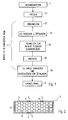
- An amount of starting material 1, for example a powdery or granular Material is first pressed in a first step S1 into a mold, For example, a plate or cuboid shape, as in later Use cases is to use.
- a mold For example, a plate or cuboid shape, as in later Use cases is to use.
- a shaping the total for the later arrangement is suitable, so one to the course of each other heat-insulating surfaces adapted course.
- the surfaces can also curved.
- a molded plate obtained by pressing in the first step S1 is then inserted into an evacuated space is introduced and heated, so that a melting is reached in step S2 of the surface, by merging the individual particles of the pressed starting material. This forms an im Essentially liquid glass layer.
- this glass layer is solidified by cooling in accordance with step S5, then the Glass layer and thus provides a closure for that within the glass layer, that is, inside the plate, between the unmelted ones arranged there Particles of the starting material reached vacuum.
- melts typically attempt to contain them inside Gas residues and / or residual liquid to escape and lead to unwanted Openings. It is therefore expedient, after melting in accordance with step S2 to selectively provide openings 3 (FIG. 2) in the glassy surface such that evaporating moisture and gases can escape easily, like that through the Steps S3 and S4 is shown.
- step S5 After cooling according to step S5, it is only necessary the openings. 3 to close, which is shown in Figure 2 by closure elements 4.
- This Closing has, as shown by step S6, after an evacuation, if necessary, to be evacuated again.
- a vacuum panel 2 inside by the particles formed the starting material 1, closely abutting supporting elements 12th contains, between which there is a vacuum, wherein the arrangement of the support elements. 2 is completed gas-tight to the outside through a glass layer 5 and possibly provided openings 3 are closed by closure elements 4. That way formed vacuum panel 2 is therefore characterized by a glass skin and has no seams on. This glass skin forms a very hard-wearing layer 5. Such formed vacuum panels 2 can therefore be further processed in a simple manner become.
- Particularly suitable as support elements 12 are silica particles.
- a vacuum panel 10 for thermal insulation purposes of FIG. 3 is in Essentially of a single or multi-walled, usually two-walled shell 11, which is (or should be) gas or airtight and the one, by a Honeycomb illustration symbolized filling of granular or powdery degassed support members 12, preferably microporous silica. Of the Interior of the shell 11 is evacuated, whereby the support members 12 close together approach and are surrounded by the shell 11 tight fitting.
- the material of Supporting elements 12 is of course made of a heat-insulating material, as well as the shell 11.
- the vacuum panel 10 be brought into the form suitable for the subsequent arrangement, ie in one adapted to the course of the heat-insulating surfaces against each other Course.
- a plate-shaped arrangement is shown.
- the sections of the shell 11, which are in the installed state come into contact with the mutually heat-insulating surfaces, provided with an additional layer 14 at least in sections.
- this additional layer 14 is essential that it the gas tightness of the shell 11 to the relevant sections substantially increased while contributing to Heat insulation itself does not have to be done. It can therefore be compact Materials such as metal foils or metal layers, such as a Aluminum foil. Such a material is relatively unreliable in terms of Injuries in the shoring, that is, in terms of the risk, during installation such to be damaged, that the tightness of the shell 11 is impaired.
- the above-mentioned adhesive bond may be a ceremoniverklebung exclusively used for assembly purposes, if the heat-insulating surfaces against each other having components not shown in any other way with each other are connected, appropriately thermally decoupled connected to each other.
- the seam 13 is vulnerable to damage in a special way, at least during installation. It is therefore expedient, as shown, also the interface, which is formed by two interconnected tabs 15 and 16, also additionally provided with an additional layer 17 or 18, where appropriate the arrangement is such that the coated tabs 15, 16 on the additional Layer 14 are foldable. Appropriately, in the associated the against each other heat-insulating surfaces a corresponding recess be provided.
- an arrangement may be provided in which one, alternatively two, seams 19 and 20 are provided such that they Continue side of the shell 11, on which the additional layer 14 is applied.
- the coating of the tabs is not required.
- the welds or seams 19 and 20 can be represented as in Fig. 2 by dashed lines, against the be folded additional layer 14, but also against the region of the shell 11, the is not provided with an additional layer 14 (in dash-dot lines ) Indicated. In the latter case, a coating must be avoided.
- Fig. 5 shows in perspective an arrangement in which the through the vacuum panel 10th formed thermal insulation is essentially cuboid, so a clear Thickness dimension has.
- a comparatively elastic shell instead of a comparatively rigid box or box-like sheath arrangement be selected which is evacuated via a nozzle or the like (not shown).
- thermal insulation with a vacuum panel 10 according to the Invention are also well stackable, which they at the sections that the additional Layer 14, relative to mechanical damage relative are insensitive, allowing intermediate storage between production and Shoring in a simple and thus cost-effective way is possible.
- the outwardly facing surface is significantly improved without affecting the thermal insulation behavior against mechanical damage and against outgassing.
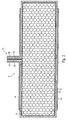
- Figure 6 shows in perspective an arrangement similar to Figure 5, in which the a vacuum panel 22 formed thermal insulation is substantially cuboid, So has a significant thickness.
- the Inner wall 24 ( Figure 7 and Figure 8) of the gas-tight envelope of the vacuum panel 22 in is formed special way, namely rib-like elevations 29 and channel-like recesses 30 has.
- the filling, not shown here granular or powder degassed support elements, preferably microporous Silica, in any case, is usually close to the projections 29 and is well, at least to a significant extent in the channel-like recesses 30th penetration.
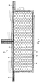
- FIG. 7 and FIG. 8 show that the entire wall construction of the casing is multi-layered is, starting from the inner wall 24 further layers 25, 26 and 27, 28. Die Number and type of material of the respective layers will vary according to the appropriate application case.
- the desired Cross section has.
- the extruded plastic pipe is cut to length and are then lid on both sides at the open ends of the extruded tube 32 gas-tight or vacuum-tight attached.
- the lid 32 has one of the walls of the extruded tube corresponding multilayer structure with an inner wall 34 and successive layers 35, 36 and 37, 38.
- the lid 32 may be glued or welded or glued or be welded on. It may also be a partially shown in Figure 8 into each other engaging in training.
- the evacuation port 31 evacuates carried out, after which this evacuation port 31 is sealed.
- a vacuum panel 22 designed in this way has very high inherent rigidity and is therefore more usable in many applications than vacuum panels with only small thickness and thin bag-like casing, even if these, such as explained above, is coated by an additional layer. Further suitable Such an embodiment is better for industrial production with high Quantities.
- suitable for the layer 24 is a polyamide
- for the layers 25 and 27 is an EVOH and for layers 26 and 28 is a PE (polyethylene).
- Vacuum panels according to the present invention in addition to the desired heat-insulating feature an additional feature in particular to namely, that the materials of the shell and the support material specifically to improve the Schalldämmargueses the overall arrangement, in which the Vacuum panel is used to improve.
- vacuum panels can not only increase the thermal insulation, but also to improve the sound insulation, even together be used.
- FIG. 9 shows a partial section of a vacuum panel 41, which initially has a vacuum inside Arrangement of a shell 42 and a filling 43, for example, from a powdery or granular material, eg. Fumed silica, has, wherein this arrangement is evacuated.
- This arrangement 42, 43 is as shown Figure 9 seen completely surrounded by a plastic material, this Plastic material is formed as encapsulation or Umg cordung 44.
- Such a vacuum panel 41 can be by introducing the assembly 42, 43 in a mold and by molding or encapsulation in this form by means of a suitable plastic material, such as polyurethane comparatively easy to produce. It is advantageous if the shell 42 is formed by a metallized film.
- the vacuum panel 41 allows the Outer side surfaces of the extrusion coating or Umg electung 44 to an application adapted to form, for example by casting or molding of Projections.
- strip-like projections 45 are with Dovetail-shaped cross-section on opposite sides Outer side surfaces of the enclosure or Umg electung 44 of the vacuum panel 41st formed. This makes it possible in a simple manner, the vacuum panel 41st introduce between each other heat to be insulated components.
Landscapes
- Engineering & Computer Science (AREA)
- General Engineering & Computer Science (AREA)
- Physics & Mathematics (AREA)
- Architecture (AREA)
- Mechanical Engineering (AREA)
- Acoustics & Sound (AREA)
- Electromagnetism (AREA)
- Civil Engineering (AREA)
- Structural Engineering (AREA)
- Thermal Insulation (AREA)
- Building Environments (AREA)
Applications Claiming Priority (4)
| Application Number | Priority Date | Filing Date | Title |
|---|---|---|---|
| DE102004003603 | 2004-01-23 | ||
| DE102004003603A DE102004003603A1 (de) | 2004-01-23 | 2004-01-23 | Verfahren zum Herstellen eines Vakuumpaneels, sowie Vakuumpaneel, insbesondere für Wärmedämmzwecke |
| DE102004010939 | 2004-03-05 | ||
| DE102004010939A DE102004010939A1 (de) | 2004-01-23 | 2004-03-05 | Verfahren zum Herstellen eines Vakuumpaneels, sowie Vakuumpaneel, insbesondere für Wärmedämmzwecke |
Publications (1)
| Publication Number | Publication Date |
|---|---|
| EP1557504A2 true EP1557504A2 (fr) | 2005-07-27 |
Family
ID=34635220
Family Applications (1)
| Application Number | Title | Priority Date | Filing Date |
|---|---|---|---|
| EP05001235A Withdrawn EP1557504A2 (fr) | 2004-01-23 | 2005-01-21 | Procédé de fabrication d'un panneau isolant sous vide, et panneau isolant sous vide notamment pour l'isolation thermique |
Country Status (2)
| Country | Link |
|---|---|
| EP (1) | EP1557504A2 (fr) |
| DE (1) | DE102004010939A1 (fr) |
Cited By (5)
| Publication number | Priority date | Publication date | Assignee | Title |
|---|---|---|---|---|
| DE102007013584A1 (de) | 2006-12-13 | 2008-09-25 | Woschko Winlite Gmbh | Verfahren zur Herstellung eines Vakuumpaneels, derartiges Vakuumpaneel sowie ein dieses verwendender Mauerstein |
| CN101504105B (zh) * | 2009-03-12 | 2010-06-16 | 成都思摩纳米技术有限公司 | 玻璃钢整体复合真空绝热板及其制造方法和应用 |
| EP2484951A1 (fr) * | 2005-10-18 | 2012-08-08 | LG Electronics Inc. | Panneau d'isolation sous vide et structure isolante de réfrigérateur l'appliquant |
| CN104878845A (zh) * | 2015-05-19 | 2015-09-02 | 晟通科技集团有限公司 | 无机复合保温板及其制备方法 |
| CN112739523A (zh) * | 2018-08-22 | 2021-04-30 | 哈金森公司 | 3d热成型元件 |
Families Citing this family (1)
| Publication number | Priority date | Publication date | Assignee | Title |
|---|---|---|---|---|
| US11808039B1 (en) | 2020-10-09 | 2023-11-07 | William W. Warwick, IV | Structural insulated panel |
-
2004
- 2004-03-05 DE DE102004010939A patent/DE102004010939A1/de not_active Ceased
-
2005
- 2005-01-21 EP EP05001235A patent/EP1557504A2/fr not_active Withdrawn
Cited By (5)
| Publication number | Priority date | Publication date | Assignee | Title |
|---|---|---|---|---|
| EP2484951A1 (fr) * | 2005-10-18 | 2012-08-08 | LG Electronics Inc. | Panneau d'isolation sous vide et structure isolante de réfrigérateur l'appliquant |
| DE102007013584A1 (de) | 2006-12-13 | 2008-09-25 | Woschko Winlite Gmbh | Verfahren zur Herstellung eines Vakuumpaneels, derartiges Vakuumpaneel sowie ein dieses verwendender Mauerstein |
| CN101504105B (zh) * | 2009-03-12 | 2010-06-16 | 成都思摩纳米技术有限公司 | 玻璃钢整体复合真空绝热板及其制造方法和应用 |
| CN104878845A (zh) * | 2015-05-19 | 2015-09-02 | 晟通科技集团有限公司 | 无机复合保温板及其制备方法 |
| CN112739523A (zh) * | 2018-08-22 | 2021-04-30 | 哈金森公司 | 3d热成型元件 |
Also Published As
| Publication number | Publication date |
|---|---|
| DE102004010939A1 (de) | 2005-11-03 |
Similar Documents
| Publication | Publication Date | Title |
|---|---|---|
| EP2276961B1 (fr) | Plaque d'isolation sous vide et son procédé de production | |
| EP1926931B1 (fr) | Procede pour fabriquer un element d'isolation par le vide, enveloppe d'une pellicule et rempli de poudre | |
| EP1177879B1 (fr) | Corps thermoisolant conditionné sous vide et procédé d'obtention | |
| DE69623382T2 (de) | Wärmeisolierter doppelwandiger Kunststoffbehälter | |
| EP2997292B1 (fr) | Procédé de fabrication d'un corps d'isolation sous vide | |
| EP3117135B1 (fr) | Panneau isolant sous vide et contenant équipé de panneaux isolants sous vide | |
| WO2011032299A1 (fr) | Élément à structure alvéolaire | |
| DE10058566A1 (de) | Folienumhüllter, evakuierter Wärmedämmkörper und Herstellungsverfahren für diesen | |
| DE3143659A1 (de) | Trockenmittelapplikation fuer eine isolierverglasung oder dergleichen sowie ein mit der trockenmittelapplikation gefuelltes abstandhalterprofil | |
| WO2014056614A2 (fr) | Unité de vitrage isolant | |
| WO1997049887A1 (fr) | Element en verre pour isolation | |
| EP2089586B1 (fr) | Procédé de fabrication d'un panneau à vide intérieur, panneau à vide intérieur ainsi obtenu et maçonnerie réalisée à l'aide de ce panneau | |
| DE102014003413A1 (de) | Vakuumisolationspaneel und Behälter mit Vakuumisolationspaneelen | |
| DE112005000069B4 (de) | Vakuum-Wärmeisoliermaterial, Wärmeisolier-Vorrichtung, in der dieses Material verwendet wird und Kühl-Gefrier-Vorrichtung | |
| EP1557504A2 (fr) | Procédé de fabrication d'un panneau isolant sous vide, et panneau isolant sous vide notamment pour l'isolation thermique | |
| EP1557249A2 (fr) | Procédé pour produire des briques thermo-isolants multicouches et telles briques | |
| DE102004050549B4 (de) | Folienumhüllte Vakuumdämmplatte und Verfahren zur Herstellung derselben | |
| DE102004003603A1 (de) | Verfahren zum Herstellen eines Vakuumpaneels, sowie Vakuumpaneel, insbesondere für Wärmedämmzwecke | |
| EP0771995B1 (fr) | Procédé de construction d'un panneau superisolant, panneau superisolant et son utilisation | |
| EP0619452B1 (fr) | Appareil comportant des parois isolées avec poudre sous vide | |
| EP0753638A1 (fr) | Ecarteur pour vitrage isolant | |
| EP2406454A1 (fr) | Ecarteur pour vitrages isolants | |
| DE102015112152A1 (de) | Verfahren zur Herstellung eines Dämmelements sowie ein entsprechendes Dämmelement | |
| EP0106103A1 (fr) | Procédé de fabrication d'éléments sous vide pour l'isolation thermique | |
| DE102011050632A1 (de) | Wabenelement zur Dämmung |
Legal Events
| Date | Code | Title | Description |
|---|---|---|---|
| PUAI | Public reference made under article 153(3) epc to a published international application that has entered the european phase |
Free format text: ORIGINAL CODE: 0009012 |
|
| AK | Designated contracting states |
Kind code of ref document: A2 Designated state(s): AT BE BG CH CY CZ DE DK EE ES FI FR GB GR HU IE IS IT LI LT LU MC NL PL PT RO SE SI SK TR |
|
| AX | Request for extension of the european patent |
Extension state: AL BA HR LV MK YU |
|
| STAA | Information on the status of an ep patent application or granted ep patent |
Free format text: STATUS: THE APPLICATION IS DEEMED TO BE WITHDRAWN |
|
| 18D | Application deemed to be withdrawn |
Effective date: 20110801 |