EP1557504A2 - Method of manufacturing a vacuum insulation panel, and a vacuum insulation panel particularly for heat insulation - Google Patents
Method of manufacturing a vacuum insulation panel, and a vacuum insulation panel particularly for heat insulation Download PDFInfo
- Publication number
- EP1557504A2 EP1557504A2 EP05001235A EP05001235A EP1557504A2 EP 1557504 A2 EP1557504 A2 EP 1557504A2 EP 05001235 A EP05001235 A EP 05001235A EP 05001235 A EP05001235 A EP 05001235A EP 1557504 A2 EP1557504 A2 EP 1557504A2
- Authority
- EP
- European Patent Office
- Prior art keywords
- vacuum panel
- additional layer
- panel according
- vacuum
- shell
- Prior art date
- Legal status (The legal status is an assumption and is not a legal conclusion. Google has not performed a legal analysis and makes no representation as to the accuracy of the status listed.)
- Withdrawn
Links
Images


Classifications
-
- E—FIXED CONSTRUCTIONS
- E04—BUILDING
- E04B—GENERAL BUILDING CONSTRUCTIONS; WALLS, e.g. PARTITIONS; ROOFS; FLOORS; CEILINGS; INSULATION OR OTHER PROTECTION OF BUILDINGS
- E04B1/00—Constructions in general; Structures which are not restricted either to walls, e.g. partitions, or floors or ceilings or roofs
- E04B1/62—Insulation or other protection; Elements or use of specified material therefor
- E04B1/74—Heat, sound or noise insulation, absorption, or reflection; Other building methods affording favourable thermal or acoustical conditions, e.g. accumulating of heat within walls
- E04B1/76—Heat, sound or noise insulation, absorption, or reflection; Other building methods affording favourable thermal or acoustical conditions, e.g. accumulating of heat within walls specifically with respect to heat only
- E04B1/78—Heat insulating elements
- E04B1/80—Heat insulating elements slab-shaped
- E04B1/803—Heat insulating elements slab-shaped with vacuum spaces included in the slab
-
- F—MECHANICAL ENGINEERING; LIGHTING; HEATING; WEAPONS; BLASTING
- F16—ENGINEERING ELEMENTS AND UNITS; GENERAL MEASURES FOR PRODUCING AND MAINTAINING EFFECTIVE FUNCTIONING OF MACHINES OR INSTALLATIONS; THERMAL INSULATION IN GENERAL
- F16L—PIPES; JOINTS OR FITTINGS FOR PIPES; SUPPORTS FOR PIPES, CABLES OR PROTECTIVE TUBING; MEANS FOR THERMAL INSULATION IN GENERAL
- F16L59/00—Thermal insulation in general
- F16L59/06—Arrangements using an air layer or vacuum
- F16L59/065—Arrangements using an air layer or vacuum using vacuum
-
- Y—GENERAL TAGGING OF NEW TECHNOLOGICAL DEVELOPMENTS; GENERAL TAGGING OF CROSS-SECTIONAL TECHNOLOGIES SPANNING OVER SEVERAL SECTIONS OF THE IPC; TECHNICAL SUBJECTS COVERED BY FORMER USPC CROSS-REFERENCE ART COLLECTIONS [XRACs] AND DIGESTS
- Y02—TECHNOLOGIES OR APPLICATIONS FOR MITIGATION OR ADAPTATION AGAINST CLIMATE CHANGE
- Y02A—TECHNOLOGIES FOR ADAPTATION TO CLIMATE CHANGE
- Y02A30/00—Adapting or protecting infrastructure or their operation
- Y02A30/24—Structural elements or technologies for improving thermal insulation
- Y02A30/242—Slab shaped vacuum insulation
-
- Y—GENERAL TAGGING OF NEW TECHNOLOGICAL DEVELOPMENTS; GENERAL TAGGING OF CROSS-SECTIONAL TECHNOLOGIES SPANNING OVER SEVERAL SECTIONS OF THE IPC; TECHNICAL SUBJECTS COVERED BY FORMER USPC CROSS-REFERENCE ART COLLECTIONS [XRACs] AND DIGESTS
- Y02—TECHNOLOGIES OR APPLICATIONS FOR MITIGATION OR ADAPTATION AGAINST CLIMATE CHANGE
- Y02B—CLIMATE CHANGE MITIGATION TECHNOLOGIES RELATED TO BUILDINGS, e.g. HOUSING, HOUSE APPLIANCES OR RELATED END-USER APPLICATIONS
- Y02B80/00—Architectural or constructional elements improving the thermal performance of buildings
- Y02B80/10—Insulation, e.g. vacuum or aerogel insulation
Definitions
- the invention relates to a method for producing a vacuum panel, as well as a Such vacuum panel, especially for thermal insulation purposes.
- such a vacuum panel consists of a single or multi-walled gastight envelope and a filling of granular or powder degassed Support elements, wherein the interior of the shell is evacuated, wherein the support elements are close together and are tightly surrounded by the shell.
- Such vacuum panels are known in many forms, for example EP 0 106 103 A1, US Pat. No. 4,668,551, WO 00/71849 A1.
- Such vacuum panels are used for thermal insulation between each other heat-insulating surfaces brought to the plant.
- they will placed between two shells of a multi-walled brick or in one Component introduced, one part of which is outboard and the other part is internal, these two parts are preferably thermally separated, such as in window frame assemblies and the like, such as for example, not exhaustively listed in the aforementioned WO 00/71849 A1 are.
- the single-layer or multi-layered shell is not sufficiently gastight, so that the ingress of gas from the environment Vacuum within the envelope is impaired, even when installed, so that the thermal insulation decreases.
- the shell is especially at Shoring, that is the attachment between heat-insulating against each other Surfaces prone to injury, especially in the contact area to these surfaces.
- a vacuum panel be improved so that the functionality, in particular the Thermal insulation achieved with higher security, or a longer period of time can be.
- this object is achieved by a method for producing a vacuum panel with the features of Claim 1, as well as by a corresponding vacuum panel according to the Features of claim 19.
- Essential for this aspect of the present invention is that through the surface-side glass forming a vacuum panel is created that does not have seams has and has a fairly durable surface.
- the object is achieved according to a second aspect of the invention by a method with the features of claim 5 and a vacuum panel with the features of claim 23 solved.
- This aspect of the present invention is achieved by the corresponding dependent claims.
- This aspect of the invention is based on the knowledge that with a partial coating, occupancy or planking the surface of a vacuum panel with sheath security against Reduction of the vacuum by "outgassing" on the one hand and the protection against On the other hand, injury during shoring is greatly increased, but no thermal bridge between mutually heat-insulating surfaces is created.
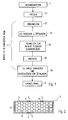
- An amount of starting material 1, for example a powdery or granular Material is first pressed in a first step S1 into a mold, For example, a plate or cuboid shape, as in later Use cases is to use.
- a mold For example, a plate or cuboid shape, as in later Use cases is to use.
- a shaping the total for the later arrangement is suitable, so one to the course of each other heat-insulating surfaces adapted course.
- the surfaces can also curved.
- a molded plate obtained by pressing in the first step S1 is then inserted into an evacuated space is introduced and heated, so that a melting is reached in step S2 of the surface, by merging the individual particles of the pressed starting material. This forms an im Essentially liquid glass layer.
- this glass layer is solidified by cooling in accordance with step S5, then the Glass layer and thus provides a closure for that within the glass layer, that is, inside the plate, between the unmelted ones arranged there Particles of the starting material reached vacuum.
- melts typically attempt to contain them inside Gas residues and / or residual liquid to escape and lead to unwanted Openings. It is therefore expedient, after melting in accordance with step S2 to selectively provide openings 3 (FIG. 2) in the glassy surface such that evaporating moisture and gases can escape easily, like that through the Steps S3 and S4 is shown.
- step S5 After cooling according to step S5, it is only necessary the openings. 3 to close, which is shown in Figure 2 by closure elements 4.
- This Closing has, as shown by step S6, after an evacuation, if necessary, to be evacuated again.
- a vacuum panel 2 inside by the particles formed the starting material 1, closely abutting supporting elements 12th contains, between which there is a vacuum, wherein the arrangement of the support elements. 2 is completed gas-tight to the outside through a glass layer 5 and possibly provided openings 3 are closed by closure elements 4. That way formed vacuum panel 2 is therefore characterized by a glass skin and has no seams on. This glass skin forms a very hard-wearing layer 5. Such formed vacuum panels 2 can therefore be further processed in a simple manner become.
- Particularly suitable as support elements 12 are silica particles.
- a vacuum panel 10 for thermal insulation purposes of FIG. 3 is in Essentially of a single or multi-walled, usually two-walled shell 11, which is (or should be) gas or airtight and the one, by a Honeycomb illustration symbolized filling of granular or powdery degassed support members 12, preferably microporous silica. Of the Interior of the shell 11 is evacuated, whereby the support members 12 close together approach and are surrounded by the shell 11 tight fitting.
- the material of Supporting elements 12 is of course made of a heat-insulating material, as well as the shell 11.
- the vacuum panel 10 be brought into the form suitable for the subsequent arrangement, ie in one adapted to the course of the heat-insulating surfaces against each other Course.
- a plate-shaped arrangement is shown.
- the sections of the shell 11, which are in the installed state come into contact with the mutually heat-insulating surfaces, provided with an additional layer 14 at least in sections.
- this additional layer 14 is essential that it the gas tightness of the shell 11 to the relevant sections substantially increased while contributing to Heat insulation itself does not have to be done. It can therefore be compact Materials such as metal foils or metal layers, such as a Aluminum foil. Such a material is relatively unreliable in terms of Injuries in the shoring, that is, in terms of the risk, during installation such to be damaged, that the tightness of the shell 11 is impaired.
- the above-mentioned adhesive bond may be a ceremoniverklebung exclusively used for assembly purposes, if the heat-insulating surfaces against each other having components not shown in any other way with each other are connected, appropriately thermally decoupled connected to each other.
- the seam 13 is vulnerable to damage in a special way, at least during installation. It is therefore expedient, as shown, also the interface, which is formed by two interconnected tabs 15 and 16, also additionally provided with an additional layer 17 or 18, where appropriate the arrangement is such that the coated tabs 15, 16 on the additional Layer 14 are foldable. Appropriately, in the associated the against each other heat-insulating surfaces a corresponding recess be provided.
- an arrangement may be provided in which one, alternatively two, seams 19 and 20 are provided such that they Continue side of the shell 11, on which the additional layer 14 is applied.
- the coating of the tabs is not required.
- the welds or seams 19 and 20 can be represented as in Fig. 2 by dashed lines, against the be folded additional layer 14, but also against the region of the shell 11, the is not provided with an additional layer 14 (in dash-dot lines ) Indicated. In the latter case, a coating must be avoided.
- Fig. 5 shows in perspective an arrangement in which the through the vacuum panel 10th formed thermal insulation is essentially cuboid, so a clear Thickness dimension has.
- a comparatively elastic shell instead of a comparatively rigid box or box-like sheath arrangement be selected which is evacuated via a nozzle or the like (not shown).
- thermal insulation with a vacuum panel 10 according to the Invention are also well stackable, which they at the sections that the additional Layer 14, relative to mechanical damage relative are insensitive, allowing intermediate storage between production and Shoring in a simple and thus cost-effective way is possible.
- the outwardly facing surface is significantly improved without affecting the thermal insulation behavior against mechanical damage and against outgassing.
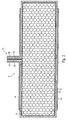
- Figure 6 shows in perspective an arrangement similar to Figure 5, in which the a vacuum panel 22 formed thermal insulation is substantially cuboid, So has a significant thickness.
- the Inner wall 24 ( Figure 7 and Figure 8) of the gas-tight envelope of the vacuum panel 22 in is formed special way, namely rib-like elevations 29 and channel-like recesses 30 has.
- the filling, not shown here granular or powder degassed support elements, preferably microporous Silica, in any case, is usually close to the projections 29 and is well, at least to a significant extent in the channel-like recesses 30th penetration.
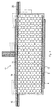
- FIG. 7 and FIG. 8 show that the entire wall construction of the casing is multi-layered is, starting from the inner wall 24 further layers 25, 26 and 27, 28. Die Number and type of material of the respective layers will vary according to the appropriate application case.
- the desired Cross section has.
- the extruded plastic pipe is cut to length and are then lid on both sides at the open ends of the extruded tube 32 gas-tight or vacuum-tight attached.
- the lid 32 has one of the walls of the extruded tube corresponding multilayer structure with an inner wall 34 and successive layers 35, 36 and 37, 38.
- the lid 32 may be glued or welded or glued or be welded on. It may also be a partially shown in Figure 8 into each other engaging in training.
- the evacuation port 31 evacuates carried out, after which this evacuation port 31 is sealed.
- a vacuum panel 22 designed in this way has very high inherent rigidity and is therefore more usable in many applications than vacuum panels with only small thickness and thin bag-like casing, even if these, such as explained above, is coated by an additional layer. Further suitable Such an embodiment is better for industrial production with high Quantities.
- suitable for the layer 24 is a polyamide
- for the layers 25 and 27 is an EVOH and for layers 26 and 28 is a PE (polyethylene).
- Vacuum panels according to the present invention in addition to the desired heat-insulating feature an additional feature in particular to namely, that the materials of the shell and the support material specifically to improve the Schalldämmargueses the overall arrangement, in which the Vacuum panel is used to improve.
- vacuum panels can not only increase the thermal insulation, but also to improve the sound insulation, even together be used.
- FIG. 9 shows a partial section of a vacuum panel 41, which initially has a vacuum inside Arrangement of a shell 42 and a filling 43, for example, from a powdery or granular material, eg. Fumed silica, has, wherein this arrangement is evacuated.
- This arrangement 42, 43 is as shown Figure 9 seen completely surrounded by a plastic material, this Plastic material is formed as encapsulation or Umg cordung 44.
- Such a vacuum panel 41 can be by introducing the assembly 42, 43 in a mold and by molding or encapsulation in this form by means of a suitable plastic material, such as polyurethane comparatively easy to produce. It is advantageous if the shell 42 is formed by a metallized film.
- the vacuum panel 41 allows the Outer side surfaces of the extrusion coating or Umg electung 44 to an application adapted to form, for example by casting or molding of Projections.
- strip-like projections 45 are with Dovetail-shaped cross-section on opposite sides Outer side surfaces of the enclosure or Umg electung 44 of the vacuum panel 41st formed. This makes it possible in a simple manner, the vacuum panel 41st introduce between each other heat to be insulated components.
Landscapes
- Engineering & Computer Science (AREA)
- General Engineering & Computer Science (AREA)
- Physics & Mathematics (AREA)
- Architecture (AREA)
- Mechanical Engineering (AREA)
- Acoustics & Sound (AREA)
- Electromagnetism (AREA)
- Civil Engineering (AREA)
- Structural Engineering (AREA)
- Thermal Insulation (AREA)
- Building Environments (AREA)
Abstract
Description
Die Erfindung betrifft ein Verfahren zum Herstellen eines Vakuumpaneels, sowie ein derartiges Vakuumpaneel, insbesondere für Wärmedämmzwecke.The invention relates to a method for producing a vacuum panel, as well as a Such vacuum panel, especially for thermal insulation purposes.
Wesentlich bei solchen Vakuumpaneelen ist der vakuumdichte Abschluss einer Füllung aus körnigen oder pulverförmigen entgasten Stützelementen, insbesondere Kieselsäure-Partikeln, nach Außen, wobei das Innere evakuiert ist und wobei die Stützelemente eng aneinandergerückt sind.Essential in such vacuum panels is the vacuum-tight completion of a Filling of granular or powder degassed support elements, in particular Silica particles, to the outside, wherein the interior is evacuated and wherein the Support elements are close together.
Typisch besteht ein solches Vakuumpaneel aus einer ein- oder mehrwandigen gasdichten Hülle und einer Füllung aus körnigen oder pulverförmigen entgasten Stützelementen, wobei das Innere der Hülle evakuiert ist, wobei die Stützelemente eng aneinandergerückt sind und von der Hülle enganliegend umgeben sind.Typically, such a vacuum panel consists of a single or multi-walled gastight envelope and a filling of granular or powder degassed Support elements, wherein the interior of the shell is evacuated, wherein the support elements are close together and are tightly surrounded by the shell.
Derartige Vakuumpaneele sind in vielfältiger Form bekannt, beispielsweise aus EP 0 106 103 A1, US 4,668,551, WO 00/71849 A1.Such vacuum panels are known in many forms, for example EP 0 106 103 A1, US Pat. No. 4,668,551, WO 00/71849 A1.
Derartige Vakuumpaneele werden zu Wärmedämmzwecken zwischen gegeneinander wärmezudämmende Flächen zur Anlage gebracht. Beispielsweise werden sie zwischen zwei Schalen eines mehrschaligen Mauersteins gebracht oder in ein Bauelement eingeführt, dessen einer Teil außenliegend und dessen anderer Teil innenliegend ist, wobei diese beiden Teile vorzugsweise thermisch getrennt sind, wie etwa bei Fensterrahmenanordnungen und dergleichen Anwendungen, wie sie beispielsweise in der vorgenannten WO 00/71849 A1 nicht abschließend aufgeführt sind.Such vacuum panels are used for thermal insulation between each other heat-insulating surfaces brought to the plant. For example, they will placed between two shells of a multi-walled brick or in one Component introduced, one part of which is outboard and the other part is internal, these two parts are preferably thermally separated, such as in window frame assemblies and the like, such as for example, not exhaustively listed in the aforementioned WO 00/71849 A1 are.
Derartige Vakuumpaneele haben jedoch einige Nachteile, die den Wärmedämmeffekt gravierend beeinflussen. Zum einen ist die ein- oder mehrlagige Hülle nicht ausreichend gasdicht, sodass durch Eindringen von Gas aus der Umgebung das Vakuum innerhalb der Hülle beeinträchtigt wird, auch im eingebauten Zustand, sodass die Wärmedämmung nachlässt. Zum anderen ist die Hülle insbesondere beim Verbau, das heißt der Anbringung zwischen gegeneinander wärmezudämmenden Flächen anfällig für Verletzung, insbesondere im Kontaktbereich zu diesen Flächen.However, such vacuum panels have some disadvantages that the thermal insulation effect seriously affect. For one thing, the single-layer or multi-layered shell is not sufficiently gastight, so that the ingress of gas from the environment Vacuum within the envelope is impaired, even when installed, so that the thermal insulation decreases. On the other hand, the shell is especially at Shoring, that is the attachment between heat-insulating against each other Surfaces prone to injury, especially in the contact area to these surfaces.
Ausgehend hiervon ist es Aufgabe der vorliegenden Erfindung, ein Vakuumpaneel dahingehend zu verbessern, dass die Funktionsfähigkeit, insbesondere die Wärmedämmwirkung mit höherer Sicherheit, bzw. höherer Zeitdauer erreicht werden kann.Based on this, it is an object of the present invention, a vacuum panel be improved so that the functionality, in particular the Thermal insulation achieved with higher security, or a longer period of time can be.
Gemäß einem ersten Aspekt der vorliegenden Erfindung wird diese Aufgabe durch
ein Verfahren zur Herstellung eines Vakuumpaneels mit den Merkmalen des
Anspruchs 1 gelöst, sowie durch ein entsprechendes Vakuumpaneel gemäß den
Merkmalen des Anspruchs 19.According to a first aspect of the present invention, this object is achieved by
a method for producing a vacuum panel with the features of
Dieser Aspekt der vorliegenden Erfindung wird durch die entsprechenden abhängigen Ansprüche weitergebildet.This aspect of the present invention is characterized by the corresponding dependent claims developed.
Wesentlich für diesen Aspekt der vorliegenden Erfindung ist, dass durch die oberflächenseitige Glasbildung ein Vakuumpaneel geschaffen wird, das keine Nähte hat und eine ziemlich strapazierfähige Oberfläche besitzt.Essential for this aspect of the present invention is that through the surface-side glass forming a vacuum panel is created that does not have seams has and has a fairly durable surface.
Die Aufgabe wird gemäß einem zweiten Aspekt der Erfindung durch ein Verfahren
mit den Merkmalen des Anspruches 5 bzw. ein Vakuumpaneel mit den Merkmalen
des Anspruchs 23 gelöst. Dieser Aspekt der vorliegenden Erfindung wird durch die
entsprechenden abhängigen Ansprüche weitergebildet. Dieser Aspekt der Erfindung
geht dabei von der Erkenntnis aus, dass bei einer teilweisen Beschichtung, Belegung
oder Beplankung der Fläche eines Vakuumpaneels mit Hülle die Sicherheit gegen
Verringerung des Vakuums durch "Ausgasen" einerseits und der Schutz gegen
Verletzung beim Verbau andererseits stark erhöht ist, jedoch keine Wärmebrücke
zwischen gegeneinander wärmezudämmende Flächen geschaffen wird.The object is achieved according to a second aspect of the invention by a method
with the features of
Die Erfindung wird anhand der in der Zeichnung dargestellten Ausführungsbeispiele näher erläutert. Es zeigen
Figur 1- schematisch den Verfahrensablauf beim Herstellen eines Vakuumpaneels gemäß dem ersten Aspekt der vorliegenden Erfindung,
Figur 2- schematisch im Schnitt ein Vakuumpaneel gemäß dem ersten Aspekt der vorliegenden Erfindung,
Figur 3- im Schnitt den grundsätzlichen Aufbau eines Vakuumpaneels gemäß dem zweiten Aspekt der vorliegenden Erfindung,
- Figur 4
- eine Weiterbildung des Vakuumpaneels gemäß
Figur 3, Figur 5- eine andere Ausführungsform des Vakuumpaneels gemäß dem zweiten Aspekt der vorliegenden Erfindung,
- Figur 6
- schematisch und perspektivisch ein Vakuumpaneel gemäß einem 3. Aspekt der vorliegenden Erfindung,
Figur 7- den Schnitt A-A in Figur 6,
- Figur 8
- den Schnitt B-B in Figur 6,
- Figur 9
- schematisch/perspektivisch und in Teilschnitt ein Vakuumpaneel gemäß einem 4. Aspekt der vorliegenden Erfindung,
Figur 10- vergrößert die Einzelheit X in Figur 9.
- FIG. 1
- 1 is a schematic view of the process of manufacturing a vacuum panel according to the first aspect of the present invention;
- FIG. 2
- schematically in section a vacuum panel according to the first aspect of the present invention,
- FIG. 3
- in section the basic structure of a vacuum panel according to the second aspect of the present invention,
- FIG. 4
- a development of the vacuum panel according to FIG. 3,
- FIG. 5
- another embodiment of the vacuum panel according to the second aspect of the present invention,
- FIG. 6
- schematically and in perspective a vacuum panel according to a third aspect of the present invention,
- FIG. 7
- the section AA in Figure 6,
- FIG. 8
- the section BB in Figure 6,
- FIG. 9
- schematic / perspective and in partial section a vacuum panel according to a fourth aspect of the present invention,
- FIG. 10
- increases the detail X in Figure 9.
In einem ersten Aspekt der vorliegenden Erfindung, der anhand der Figuren 1 und 2 erläutert wird, wird von der Erkenntnis ausgegangen, dass durch eine Verglasung einer Oberfläche eine einerseits sehr strapazierfähige Oberfläche geschaffen wird, die andererseits gas- und damit auch vakuumdicht ist.In a first aspect of the present invention, with reference to Figures 1 and 2 is explained, it is assumed that by glazing a surface is created on the one hand very hard-wearing surface, the other hand, gas and thus vacuum-tight.
Eine Menge an Ausgangsmaterial 1, ein beispielsweise pulverförmiges oder körniges
Material, wird zunächst in einem ersten Schritt S1 in eine Form gepresst,
beispielsweise eine platten- oder quaderförmige Form, wie sie bei späteren
Anwendungsfällen zu verwenden ist. Bei einer Anwendung zu Wärmedämmzwecken
wird durch diesen ersten Schritt S1 eine Formgebung erreicht, die insgesamt für die
spätere Anordnung geeignet ist, also ein an den Verlauf der gegeneinander
wärmezudämmenden Flächen angepasster Verlauf. Somit können die Oberflächen
auch gekrümmt verlaufen.An amount of starting
Eine in dem ersten Schritt S1 durch Pressen erreichte geformte Platte wird dann in einen evakuierten Raum eingebracht und erhitzt, derart, dass ein Anschmelzen gemäß Schritt S2 der Oberfläche erreicht wird, und zwar durch Verschmelzen der einzelnen Teilchen des gepressten Ausgangsmaterials. Hierdurch bildet sich eine im Wesentlichen flüssige Glasschicht.A molded plate obtained by pressing in the first step S1 is then inserted into an evacuated space is introduced and heated, so that a melting is reached in step S2 of the surface, by merging the individual particles of the pressed starting material. This forms an im Essentially liquid glass layer.
Wird diese Glasschicht durch Abkühlen gemäß Schritt S5 verfestigt, so härtet die Glasschicht aus und bietet somit einen Verschluss für das innerhalb der Glasschicht, also innerhalb der Platte, zwischen den dort angeordneten nicht geschmolzenen Partikeln des Ausgangsmaterials erreichte Vakuum.If this glass layer is solidified by cooling in accordance with step S5, then the Glass layer and thus provides a closure for that within the glass layer, that is, inside the plate, between the unmelted ones arranged there Particles of the starting material reached vacuum.
Typisch versuchen bei solchen Schmelzvorgängen jedoch im Inneren noch enthaltene Gasreste und/oder Flüssigkeitsreste zu entweichen und führen zu ungewollten Öffnungen. Zweckmäßig ist es daher, nach dem Anschmelzen gemäß Schritt S2 gezielt Öffnungen 3 (Fig. 2) in der glasigen Oberfläche vorzusehen, derart, dass verdampfende Feuchtigkeit und Gase leicht entweichen können, wie das durch die Schritte S3 und S4 dargestellt ist.However, such melts typically attempt to contain them inside Gas residues and / or residual liquid to escape and lead to unwanted Openings. It is therefore expedient, after melting in accordance with step S2 to selectively provide openings 3 (FIG. 2) in the glassy surface such that evaporating moisture and gases can escape easily, like that through the Steps S3 and S4 is shown.
Nach dem Abkühlen gemäß Schritt S5 ist es lediglich erforderlich die Öffnungen 3 zu verschließen, was in Figur 2 durch Verschlusselemente 4 dargestellt ist. Dieses Verschließen hat dabei, wie durch Schritt S6 dargestellt, nach einem Evakuieren, gegebenenfalls erneutem Evakuieren zu erfolgen.After cooling according to step S5, it is only necessary the openings. 3 to close, which is shown in Figure 2 by closure elements 4. This Closing has, as shown by step S6, after an evacuation, if necessary, to be evacuated again.
Es entsteht somit ein Vakuumpaneel 2, (Figur 2), das im Inneren durch die Partikel
des Ausgangsmaterials 1 gebildete, eng aneinanderanliegende Stützelemente 12
enthält, zwischen denen Vakuum herrscht, wobei die Anordnung der Stützelemente 2
nach außen durch eine Glasschicht 5 gasdicht abgeschlossen ist und eventuell
vorgesehene Öffnungen 3 durch Verschlusselemente 4 verschlossen sind. Das derart
gebildete Vakuumpaneel 2 zeichnet sich demnach durch eine Glashaut aus und weist
keine Nähte auf. Diese Glashaut bildet ein sehr strapazierfähige Schicht 5. Derart
gebildete Vakuumpaneele 2 können daher in einfacher Weise weiterverarbeitet
werden. Besonders geeignet als Stützelemente 12 sind Kieselsäure-Partikel.This results in a
Ein zweiter Aspekt der vorliegenden Erfindung wird anhand der Figuren 3 bis 5 näher erläutert.A second aspect of the present invention will be described with reference to FIGS. 3 to 5 explained in more detail.
Ein Vakuumpaneel 10 für Wärmedämmzwecke gemäß Fig. 3 besteht im
Wesentlichen aus einer ein- oder mehrwandigen, üblicherweise zweiwandigen Hülle
11, die gas- bzw. luftdicht ist (bzw. sein soll) und die eine, durch eine
Honigwabendarstellung symbolisierte Füllung aus körnigen oder pulverförmigen
entgasten Stützelementen 12, vorzugsweise mikroporöse Kieselsäure, enthält. Der
Innenraum der Hülle 11 ist evakuiert, wodurch die Stützelemente 12 eng aneinander
anrücken und von der Hülle 11 eng anliegend umgeben sind. Der Werkstoff der
Stützelemente 12 besteht selbstverständlich aus einem wärmeisolierendem Material,
ebenso wie die Hülle 11. Bei der Evakuierung der Hülle 11 und der anschließenden
Verschweißung, wobei der so entstehende Stutzen und die Schweißnaht symbolisch
und übertrieben als Nahtstelle 13 dargestellt sind, kann das Vakuumpaneel 10
insgesamt in die für die spätere Anordnung geeignete Form gebracht werden, also in
eine an den Verlauf der gegeneinander wärmezudämmenden Flächen angepassten
Verlauf. Beim Ausführungsbeispiel ist ein plattenförmige Anordnung dargestellt. A
Erfindungsgemäß sind dabei die Abschnitte der Hülle 11, die im verbauten Zustand
gegen die gegeneinander wärmezudämmenden Flächen jeweils zur Anlage kommen,
mit einer zusätzlichen Schicht 14 zumindest abschnittsweise versehen. Für diese
zusätzliche Schicht 14 ist wesentlich, dass sie die Gasdichtigkeit der Hülle 11 an den
entsprechenden Abschnitten wesentlich erhöht, während ein Beitrag zur
Wärmedämmung selbst nicht erfolgen muss. Es kann sich daher um kompakte
Materialien handeln, wie Metallfolien oder Metallschichten, beispielsweise eine
Aluminiumfolie. Ein solches Material ist auch relativ wenig anfällig hinsichtlich
Verletzungen beim Verbau, das heißt hinsichtlich der Gefahr, beim Verbau derart
beschädigt zu werden, dass die Dichtheit der Hülle 11 beeinträchtigt ist.According to the invention, the sections of the
Dies erlaubt es zusätzlich, eine Klebeverbindung zwischen dieser zusätzlichen
Schicht 14 und der gegenüberliegenden Seite der zugeordneten der gegeneinander
wärmezudämmenden Flächen vorzusehen, die im einzelnen nicht dargestellt sind.This additionally allows an adhesive bond between these
Die erwähnte Klebeverbindung kann eine Punktverklebung sein, die ausschließlich zu Montagezwecken dient, wenn die die gegeneinander wärmezudämmenden Flächen aufweisenden nicht näher dargestellten Bauelemente in anderer Weise miteinander verbunden sind, zweckmäßig thermisch entkoppelt miteinander verbunden sind.The above-mentioned adhesive bond may be a Punktverklebung exclusively used for assembly purposes, if the heat-insulating surfaces against each other having components not shown in any other way with each other are connected, appropriately thermally decoupled connected to each other.
Die Nahtstelle 13 ist dabei in besonderer Weise anfällig für Beschädigungen,
jedenfalls beim Einbau. Zweckmäßig ist daher, wie dargestellt, auch die Nahtstelle,
die durch zwei miteinander verbundene Laschen 15 und 16 gebildet ist, ebenfalls
zusätzlich mit einer zusätzlichen Schicht 17 bzw. 18 versehen, wobei zweckmäßig
die Anordnung derart ist, dass die beschichteten Laschen 15, 16 auf die zusätzliche
Schicht 14 faltbar sind. Zweckmäßig kann auch in der zugeordneten der
gegeneinander wärmezudämmenden Flächen eine entsprechende Vertiefung
vorgesehen sein.The
Alternativ kann, wie in Fig. 4 dargestellt, eine Anordnung vorgesehen sein, bei der
eine, alternativ zwei, Nahtstellen 19 bzw. 20 derart vorgesehen sind, dass sie die
Seite der Hülle 11 fortsetzen, auf der die zusätzliche Schicht 14 aufgebracht ist. Hier
ist die Beschichtung der Laschen nicht erforderlich. Die Schweiß- oder Nahtstellen
19 bzw. 20 können dabei wie in Fig. 2 durch Strichlinien dargestellt, gegen die
zusätzliche Schicht 14 gefaltet sein, aber auch gegen den Bereich der Hülle 11, der
nicht mit einer zusätzlichen Schicht 14 versehen ist (in Strich-Punkt-Linien
angedeutet). Im letzteren Fall ist eine Beschichtung unbedingt zu vermeiden. Alternatively, as shown in Fig. 4, an arrangement may be provided in which
one, alternatively two,
Fig. 5 zeigt perspektivisch eine Anordnung, bei der die durch das Vakuumpaneel 10 gebildete Wärmedämmung im Wesentlichen quaderförmig ist, also eine deutliche Dickenabmessung besitzt. Hier kann statt einer vergleichsweise elastischen Hülle eine vergleichsweise steife schachtel- oder boxartige Hüllenanordnung gewählt sein, die über einen Stutzen oder dergleichen (nicht dargestellt) evakuierbar ist.Fig. 5 shows in perspective an arrangement in which the through the vacuum panel 10th formed thermal insulation is essentially cuboid, so a clear Thickness dimension has. Here, instead of a comparatively elastic shell a comparatively rigid box or box-like sheath arrangement be selected which is evacuated via a nozzle or the like (not shown).
Wie dargestellt ist hier eine, und zwar die größte Seitenfläche mit einer zusätzlichen
Schicht 14 versehen, und zwar im Wesentlichen ganzflächig mit jedoch deutlichem
Abstand zu den Kanten des hier boxartigen Vakuumpaneels 21.
Selbstverständlich kann eine ganzflächige Beschichtung vorgesehen sein.As shown here is one, namely the largest side surface provided with an
Of course, a full-area coating can be provided.
Es zeigt sich ferner, dass Wärmedämmungen mit einem Vakuumpaneel 10 gemäß der
Erfindung auch gut stapelbar sind, das sie an den Abschnitten, die die zusätzliche
Schicht 14 aufweisen, gegenüber mechanischen Beschädigungen relativ
unempfindlich sind, so dass eine Zwischenlagerung zwischen Herstellung und
Verbau in einfacher und damit kostengünstiger Weise möglich ist.It also shows that thermal insulation with a
Es zeigt sich ferner, dass ein Kombination des ersten Aspektes mit dem zweiten
Aspekt der vorliegenden Erfindung grundsätzlich möglich ist, also auch die
glasartige Schicht 5 des Vakuumpaneels 2 gemäß Figur 2 zusätzlich mit einer nicht
dargestellten zusätzlichen Schicht 14 versehen werden kann und auch über eine
solche Schicht oder auch direkt von der glasartigen Oberfläche aus eine
Klebeverbindung zu der gegenüberliegenden Seite der zugeordneten der
gegeneinander wärmezudämmenden Flächen vorgesehen werden kann. Es zeigt sich,
dass durch eine eventuelle zusätzliche Schicht (ähnlich der Schicht 14 bei dem
Vakuumpaneel 10 gemäß dem zweiten Aspekt der vorliegenden Erfindung) zusätzlich
oder ergänzend die Funktion der Verschlusselemente 4 der Öffnungen 3 in der
glasartigen Schicht 5 erreicht werden kann.It also shows that a combination of the first aspect with the second
Aspect of the present invention is basically possible, including the
Bei allen Ausführungsformen der vorliegenden Erfindung ist die nach außen weisende Oberfläche ohne Beeinträchtigung des Wärmedämmverhaltens gegenüber mechanischen Beschädigungen und gegenüber Ausgasen erheblich verbessert. In all embodiments of the present invention, the outwardly facing surface is significantly improved without affecting the thermal insulation behavior against mechanical damage and against outgassing.
Figur 6 zeigt perspektivisch eine Anordnung ähnlich der Figur 5, bei der die durch
ein Vakuumpaneel 22 gebildete Wärmedämmung im wesentlichen quaderförmig ist,
also eine deutliche Dickenabmessung besitzt. Hier kann zwar wie weiter oben
diskutiert, eine vergleichsweise elastische Hülle, aber auch ein vergleichsweise steife
schachtel- oder boxartige Hüllenanordnung gewählt sein, die über einen Stutzen oder
dergleichen evakuierbar ist, was beim Ausführungsbeispiel gemäß Figur 6 durch
einen Evakuierungs-Auslass 31 schematisch dargestellt ist. Wie dargestellt ist ferner
mindestens eine Seitenfläche, und zwar die größte Seitenfläche mit einer zusätzlichen
Schicht 23 im Sinne der Ausführungsform nach Figur 5 versehen, und zwar im
wesentlichen ganzflächig mit, wie sich aus der Schnittansicht gemäß Figur 7 ergibt,
vergleichsweise geringfügigem Abstand zu den Kanten des boxartigen
Vakuumpaneels 22. Aus Figur 7 ergibt sich, dass beide großen Seitenflächen in
entsprechender Weise durch eine zusätzliche Schicht 23 beschichtet oder "beplankt"
ist. Wie weiter oben erläutert, ist es für die zusätzliche Schicht 23 wesentlich, dass
die Gasdichtigkeit des Vakuumpaneels bzw. dessen Hülle, an den entsprechenden
Wänden wesentlich erhöht ist, während ein Beitrag zur Wärmedämmung selbst nicht
erfolgen muss. Deshalb kann es sich um kompakte Materialien, wie Metallfolien
oder Metallschichten, beispielsweise eine Aluminiumfolie handeln.Figure 6 shows in perspective an arrangement similar to Figure 5, in which the
a
Gemäß dem 3. Aspekt der vorliegenden Erfindung ist es wesentlich, dass die
Innenwand 24 (Figur 7 und Figur 8) der gasdichten Hülle des Vakuumpaneels 22 in
besonderer Weise ausgebildet ist, nämlich rippenartige Erhöhungen 29 und
kanalartige Vertiefungen 30 aufweist. Die hier nicht dargestellte Füllung aus
körnigen oder pulverförmigen entgasten Stützelementen, vorzugsweise mikroporöse
Kieselsäure, liegt jedenfalls üblicherweise eng an die Vorsprünge 29 an und wird
wohl, zumindest in wesentlichem Umfang auch in die kanalartigen Vertiefungen 30
eindringen. Andererseits wird jedoch beim Erzeugen des Vakuums innerhalb der
Hülle, also beim Evakuieren durch den Evakuierungs-Auslass 31 hindurch, die Luft
zwischen den Stützelementen hindurch und längs der Innenwand 24 gesaugt, so dass
eine durch die kanalartigen Vertiefungen 30 bewirkte Kanalisierung und damit
Verbesserung und Beschleunigung des Evakuierungsvorganges erzielt wird. Bei
individueller Fertigung der Gesamthülle kann daher der Verlauf der kanalartigen
Vertiefungen 30 und der rippenartigen Erhöhungen so gewählt werden, dass die
durch den Evakuierungs-Auslass 21 abgesaugte Luft optimal strömt.According to the third aspect of the present invention, it is essential that the
Inner wall 24 (Figure 7 and Figure 8) of the gas-tight envelope of the
Figur 7 und Figur 8 zeigen, dass der gesamte Wandaufbau der Hülle mehrschichtig
ist, ausgehend von der Innenwand 24 weitere Schichten 25, 26 und 27, 28. Die
Anzahl und die Art des Materials der jeweiligen Schichten wird sich nach dem
jeweiligen Anwendungsfall richten.FIG. 7 and FIG. 8 show that the entire wall construction of the casing is multi-layered
is, starting from the
Gemäß einem weiteren Aspekt, der insbesondere beim boxartigen Aufbau eines
Vakuumpaneels 22 von Vorteil ist, wird ein Teil der Hülle des Vakuumpaneels 22
zunächst durch Extrudieren eines Kunststoffrohrs erzeugt, das den gewünschten
Querschnitt besitzt. Anschließend wird das extrudierte Kunststoffrohr abgelängt und
werden anschließend beidseitig an den offenen Enden des extrudierten Rohrs Deckel
32 gasdicht bzw. vakuumdicht befestigt. Beim dargestellten Ausführungsbeispiel
weist gemäß Figur 8 der Deckel 32 einen der Wand des extrudierten Rohres
entsprechenden mehrschichtigen Aufbau auf mit einer Innenwand 34 und
aufeinanderfolgenden Schichten 35, 36 und 37, 38.According to another aspect, in particular in the box-like structure of a
Der Deckel 32 kann eingeklebt oder eingeschweißt bzw. aufgeklebt oder
aufgeschweißt sein. Es kann auch eine in Figur 8 dargestellte teilweise ineinander
eingreifende Ausbildung gewählt werden.The
Selbstverständlich wird der Innenraum der so gebildeten Hülle mit den hier nicht dargestellten Stützelementen eng gepackt gefüllt, wie das an sich bekannt ist und wird wie oben erläutert über den Evakuierungs-Anschluss 31 die Evakuierung durchgeführt, wonach dieser Evakuierungs-Anschluss 31 dicht verschlossen wird.Of course, the interior of the envelope thus formed with the not here shown supporting elements packed tightly packed, as is well known and As explained above, the evacuation port 31 evacuates carried out, after which this evacuation port 31 is sealed.
Ein so ausgebildetes Vakuumpaneel 22 weißt sehr hohe Eigensteifigkeit auf und ist
daher bei vielen Anwendungen besser verwendbar als Vakuumpaneele mit nur
geringen Dickenabmessungen und dünner sackartiger Hülle, selbst wenn diese, wie
weiter oben erläutert, durch eine zusätzliche Schicht beschichtet ist. Ferner eignet
sich eine derartige Ausführung besser für eine industrielle Fertigung mit hohen
Stückzahlen.A
Beispielsweise eignen sich für die Schicht 24 ein Polyamid, für die Schichten 25 und
27 ein EVOH und für die Schichten 26 und 28 ein PE (Polyethylen).For example, suitable for the
Gemäß einem weiteren Aspekt der vorliegenden Erfindung ist es möglich den Vakuumpaneelen gemäß der vorliegenden Erfindung neben der erwünschten wärmedämmenden Eigenschaft eine zusätzliche Eigenschaft im besonderen Maße zu verleihen, nämlich dadurch, dass die Materialien der Hülle und des Stützmaterials gezielt zur Verbesserung des Schalldämmmaßes der Gesamtanordnung, bei der das Vakuumpaneel verwendet wird, zu verbessern.According to another aspect of the present invention, it is possible the Vacuum panels according to the present invention in addition to the desired heat-insulating feature an additional feature in particular to namely, that the materials of the shell and the support material specifically to improve the Schalldämmmaßes the overall arrangement, in which the Vacuum panel is used to improve.
Bekanntlich wird bei der Übertragungvon Schall über ein Bauteil wie eine Wand nur ein Bruchteil der auffallenden Schallenergie an der anderen Seite des Bauteils abgestrahlt, was als Schalldämmung bezeichnet wird. In der Praxis ist das Schalldämmmaß stark frequenzabhängig, sowie ferner abhängig von bestimmten anderen physikalischen Parametern, wie Biegesteifigkeit, Elastizitätsmodul, flächenbezogener Masse der Wand usw.. Zur Physik der Schalldämmung sei beispielsweise verwiesen auf Werner Schirmer (Hrsg.), technischer Lärmschutz, VDI-Verlag GmbH, Düsseldorf 1996. As is known, when transmitting sound through a component such as a wall, only a fraction of the striking sound energy on the other side of the component radiated, which is referred to as sound insulation. In practice that is Schalldämmmaß strongly frequency-dependent, as well as dependent on certain other physical parameters, such as bending stiffness, modulus of elasticity, surface related mass of the wall, etc .. To the physics of sound insulation was For example, refer to Werner Schirmer (ed.), Technical noise protection, VDI-Verlag GmbH, Dusseldorf 1996.
Insbesondere bei einer Verwendung bei zwei oder mehrschaligen Mauersteinen, bei denen zwischen den mindestens zwei Schalen ein Vakuumpaneel angeordnet ist, sind die vorstehend genannten Materialien von Vorteil.Especially when used with two or more walled bricks, at where a vacuum panel is arranged between the at least two shells are the above materials of advantage.
Zweckmäßig sind solche Materialien für den vakuumdichten bzw. gasdichten Abschluss der Stützelemente, die insbesondere dicht gegen und chemisch nicht angreifbar sind durch Stickstoff, Sauerstoff und auch dampfförmiges Wasser (insbesondere zum Korrosionsschutz).Appropriately, such materials for the vacuum-tight or gas-tight Completion of the support elements, in particular, tight against and not chemically are vulnerable to nitrogen, oxygen and also vaporous water (in particular for corrosion protection).
Somit können Vakuumpaneele nicht nur zur Erhöhung der Wärmedämmung, sondern auch zur Verbesserung der Schalldämmung, und zwar sogar gemeinsam herangezogen werden.Thus, vacuum panels can not only increase the thermal insulation, but also to improve the sound insulation, even together be used.
Es zeigt sich, dass dieser 3. Aspekt der vorliegenden Erfindung auch bei Vakuumpaneelen mit einer sackartigen Hülle anwendbar ist, insbesondere solchen wie sie weiter oben geschildert sind.It turns out that this third aspect of the present invention also in Vacuum panels with a bag-like shell is applicable, especially those as described above.
Figur 9 zeigt im Teilschnitt ein Vakuumpaneel 41, das zunächst im Inneren eine
Anordnung aus einer Hülle 42 und einer Füllung 43, die beispielsweise aus einem
pulverförmigen oder körnigen Material, z. B. pyrogene Kieselsäure, besteht,
aufweist, wobei diese Anordnung evakuiert ist. Diese Anordnung 42, 43 ist, wie aus
Figur 9 ersichtlich, von einem Kunststoffmaterial vollständig umgeben, wobei dieses
Kunststoffmaterial als Umspritzung oder Umgießung 44 ausgebildet ist.FIG. 9 shows a partial section of a
Ein derartiges Vakuumpaneel 41 läßt sich durch Einbringen der Anordnung 42, 43 in
eine Form und durch Umgießen oder Umspritzen in dieser Form mittels eines
geeigneten Kunststoffmaterials, wie Polyurethan vergleichsweise einfach herstellen.
Von Vorteil ist dabei, wenn die Hülle 42 durch eine metallisierte Folie gebildet ist.Such a
Die einfache Herstellbarkeit des Vakuumpaneels 41 erlaubt es, die
Außenseitenflächen der Umspritzung oder Umgießung 44 an einen Anwendungsfall
angepaßt auszubilden, beispielsweise durch Angießen bzw. Anformen von
Vorsprüngen. Beim Ausführungsbeispiel sind leistenartige Vorsprünge 45 mit
schwalbenschwanzförmigem Querschnitt an voneinander abgewandten
Außenseitenflächen der Umhüllung bzw. Umgießung 44 des Vakuumpaneels 41
angeformt. Hierdurch ist es in einfacher Weise möglich, das Vakuumpaneel 41
zwischen gegeneinander Wärme zu dämmende Bauelemente einzuführen. The ease of manufacture of the
Durch die Ausbildung der Umhüllung der Umspritzung oder Umgießung 44 ist ein
erhöhter Schutz der Anordnung 42, 43 erzielt.The formation of the coating of the encapsulation or
Claims (44)
dadurch gekennzeichnet, dass die Stützelemente (12) mechanisch zu einer der Vakuumpaneelgröße entsprechenden geformten Platte zusammengepresst (S1) werden,
dass die Platte in einem evakuierten Raum eingebracht wird und dieser Raum erwärmt wird,
dass die Platte in dem evakuierten Raum derart aufgeheizt wird, dass an der Oberfläche der Platte durch Verschmelzen der dort befindlichen einzelnen Stützelemente eine flüssige Glasschicht (5) ausgebildet wird, und
dass das so gebildete Paneel abgekühlt (S5) wird, wobei die flüssige Glasschicht (5) erhärtet.Method for producing a vacuum panel (2), which has a filling of granular or pulverulent degassed support elements (12), in particular silica particles, gas-tight to the outside, wherein the interior is evacuated and wherein the support elements (12) are brought close to each other,
characterized in that the support members (12) are mechanically compressed (S1) into a shaped plate corresponding to the vacuum panel size,
that the plate is placed in an evacuated space and this space is heated,
that the plate is heated in the evacuated space such that a liquid glass layer (5) is formed on the surface of the plate by fusing the individual support elements located there, and
that the panel thus formed is cooled (S5), whereby the liquid glass layer (5) hardens.
dadurch gekennzeichnet, dass bei dem Verschmelzungsvorgang in der ab- bzw. angeschmolzenen Oberfläche Öffnungen (3) gebildet werden (S3), damit verdampfende Feuchte und Gase entweichen können und dass nach dem Abkühlen (S5) die die Öffnungen aufweisende Platte evakuiert wird und dann die Öffnungen verschlossen werden (S6).Method according to claim 1,
characterized in that in the merging process in the sealed or fused surface openings (3) are formed (S3) so that evaporating moisture and gases can escape and that after cooling (S5), the openings having the plate is evacuated and then the Openings are closed (S6).
dadurch gekennzeichnet, dass die Stützelemente (12) durch pulvrige Kieselsäure gebildet sind.Method according to claim 1 or 2,
characterized in that the support elements (12) are formed by powdery silica.
dadurch gekennzeichnet, dass mindestens ein Flächenabschnitt des so gebildeten Vakuumpaneels (2) an der Außenseite mit einer zusätzlichen Schicht versehen wird.Method according to one of claims 1 to 3,
characterized in that at least one surface portion of the vacuum panel (2) thus formed is provided on the outside with an additional layer.
dadurch gekennzeichnet, dass mindestens ein Flächenabschnitt der Hülle (11) des Vakuumpaneels (10) an der Außenseite der Hülle (11) mit einer zusätzlichen Schicht (14) versehen wird.Method for producing a vacuum panel (10) consisting of a single or multi-walled gas-tight envelope (11) and a filling of granular or powdered degassed supporting elements (12), wherein the interior of the envelope (11) is evacuated, the supporting elements (11) 12) are close together and are surrounded by the shell (11) tightly,
characterized in that at least one surface portion of the shell (11) of the vacuum panel (10) on the outside of the shell (11) is provided with an additional layer (14).
dadurch gekennzeichnet, dass die Stützelemente (12) durch mikroporöse Kieselsäure gebildet sind.Method according to claim 5,
characterized in that the support elements (12) are formed by microporous silica.
dadurch gekennzeichnet, dass die zusätzliche Schicht (14) auf die Hülle (11) des Vakuumpaneels (10) aufgeklebt wird.Method according to claim 5 or 6,
characterized in that the additional layer (14) is adhered to the shell (11) of the vacuum panel (10).
dadurch gekennzeichnet, dass die Hülle (11) miteinander gasdicht verschweißte Endlaschen (15, 16) aufweist, wobei zwischen den Endlaschen (15, 16) vor deren endgültigem Verschweißen die Evakuierung erfolgt und die Endlaschen seitlich (19, 20) von einem/dem mit der zusätzlichen Schicht (14) versehenen Flächenabschnitt wegragen und von diesem weg auf die zusätzliche Schicht (14) gefaltet werden.Method according to one of claims 5 to 7,
characterized in that the sheath (11) with each other gas-tight welded end tabs (15, 16), wherein between the end tabs (15, 16) before the final welding evacuation takes place and the end tabs laterally (19, 20) of a / with projecting surface portion of the additional layer (14) and are folded away from this on the additional layer (14).
dadurch gekennzeichnet, dass die zusätzliche Schicht eine luftdichte Schicht ist.Method according to one of claims 4 to 8,
characterized in that the additional layer is an airtight layer.
dadurch gekennzeichnet, dass die zusätzliche Schicht eine Metallfolie insbesondere Aluminiumfolie ist.Method according to one of claims 4 to 9,
characterized in that the additional layer is a metal foil, in particular aluminum foil.
dadurch gekennzeichnet, dass das Vakuumpaneel (2, 10) in eine flächige Form gebracht ist, bei der zwei Seitenflächen an den Verlauf von gegeneinander wärmezudämmenden Flächen angepasst sind und im Gebrauch an diese zur Anlage kommen und mit der zusätzlichen Schicht (14) zumindest abschnittsweise versehen werden.Method according to one of claims 4 to 10
characterized in that the vacuum panel (2, 10) is brought into a two-dimensional form, are adapted to the course of mutually heat-insulating surfaces in the two side surfaces and in use come to rest against these and provided with the additional layer (14) at least in sections become.
dadurch gekennzeichnet, dass das Vakuumpaneel (10) eine Quaderform (21) definiert..Method according to one of claims 4 to 11,
characterized in that the vacuum panel (10) defines a cuboid shape (21).
dadurch gekennzeichnet, dass bei Anwendung zu Wärmedämmzwecken der der zugeordneten Fläche der gegeneinander wärmezudämmenden Flächen zugewandte Flächenabschnitt des Vakuumpaneels (2, 10) gegebenenfalls die dort vorgesehene zusätzliche Schicht (14) zum zumindest punktweisen Verkleben mit der zugeordneten Fläche der gegeneinander wärmezudämmenden Flächen verwendet wird.Method according to one of claims 1 to 12,
characterized in that when used for thermal insulation purposes of the associated surface of the mutually heat-insulating surfaces facing surface portion of the vacuum panel (2, 10) optionally provided there additional layer (14) is used for at least pointwise bonding with the associated surface of the heat insulating surfaces against each other.
dadurch gekennzeichnet, dass eine Kunststoffrohr mit rechteckigem Querschnitt extrudiert wird, das Kunststoffrohr auf die gewünschte Länge abgelängt wird, die Endöffnungen durch einen Deckel (32) gasdicht verschlossen werden, wobei der Innenraum der so gebildeten Hülle mit der Füllung gefüllt wird und anschließend die Evakuierung durchgeführt wird.Method according to one of claims 5 to 13,
characterized in that a plastic tube is extruded with a rectangular cross-section, the plastic tube is cut to the desired length, the end openings are closed by a gas-tight lid (32), wherein the interior of the shell thus formed is filled with the filling and then carried out the evacuation becomes.
dadurch gekennzeichnet, dass das Verschließen durch Verkleben, Verschweißen oder dergleichen des Deckels (32) mit dem abgelängten Kunststoffrohr erfolgt.Method according to claim 14,
characterized in that the closure by gluing, welding or the like of the lid (32) takes place with the cut plastic pipe.
dadurch gekennzeichnet, dass das Verschließen bei gefülltem Innenraum in einer Vakuumkammer stattfindet.Method according to claim 14 or 15,
characterized in that the closure takes place in a filled interior in a vacuum chamber.
dadurch gekennzeichnet, dass die Anordnung aus Hülle (42) und Füllung (43) nach Evakuierung in eine Form eingebracht wird und diese Anordnung zur Ausbildung der zusätzlichen Schicht mit einem Kunststoffmaterial umgossen oder umspritzt (44) wird.Method according to one of claims 5 to 13,
characterized in that the arrangement of sheath (42) and filling (43) is placed after evacuation in a mold and this arrangement to form the additional layer with a plastic material encapsulated or overmolded (44).
dadurch gekennzeichnet, dass beim Umgießen bzw. Umspritzen an mindestens einer ihrer Außenseitenflächen ferner mindestens ein Vorsprung (45) angeformt wird. Method according to claim 17,
characterized in that at least one projection (45) is further formed during casting or encapsulation on at least one of its outer side surfaces.
dadurch gekennzeichnet, dass während des Schmelzvorgangs zur Bildung der Glasschicht (5) erreichte Öffnungen (3) nach Außen verschlossen (4) sind.Vacuum panel according to claim 19,
characterized in that during the melting process to form the glass layer (5) reached openings (3) are closed to the outside (4).
dadurch gekennzeichnet, dass die Stützelemente (12) durch pulvrige Kieselsäure gebildet sind.Vacuum panel according to claim 19 or 20,
characterized in that the support elements (12) are formed by powdery silica.
dadurch gekennzeichnet, dass zumindest ein Flächenabschnitt an der Außenseite mit einer zusätzlichen Schicht versehen ist.Vacuum panel according to one of claims 19 to 21,
characterized in that at least one surface portion is provided on the outside with an additional layer.
bestehend aus einer ein- oder mehrwandigen gasdichten Hülle (11) und einer Füllung aus körnigen oder pulverförmigen entgasten Stützelementen (12), wobei das Innere der Hülle (11) evakuiert ist, wobei die Stützelemente (12) eng aneinandergerückt sind und von der Hülle (11) enganliegend umgeben sind, dadurch gekennzeichnet, dass das Vakuumpaneel (10) mindestens einen Flächenabschnitt aufweist, bei dem die Hülle (11) auf ihrer Außenseite mit einer zusätzlichen Schicht (14) versehen ist.Vacuum panel, in particular for thermal insulation purposes,
consisting of a single- or multi-walled gas-tight envelope (11) and a filling of granular or powder degassed support elements (12), wherein the interior of the envelope (11) is evacuated, wherein the support elements (12) are moved close together and from the shell ( 11), characterized in that the vacuum panel (10) has at least one surface portion in which the shell (11) is provided on its outside with an additional layer (14).
dadurch gekennzeichnet, dass die Stützelemente (12) durch mikroporöse Kieselsäure gebildet sind.Vacuum panel according to claim 23,
characterized in that the support elements (12) are formed by microporous silica.
dadurch gekennzeichnet, dass die zusätzliche Schicht (14) auf die Hülle (11) des Vakuumpaneels (10) aufgeklebt ist.Vacuum panel according to claim 23 or 24,
characterized in that the additional layer (14) is adhered to the shell (11) of the vacuum panel (10).
dadurch gekennzeichnet, dass die Hülle (11) miteinander gasdicht verschweißte Endlaschen (15, 16) aufweist, wobei zwischen den Endlaschen (15, 16) vor deren endgültigem Verschweißen die Evakuierung erfolgt und die Endlaschen seitlich (19, 20) von einem/dem mit der zusätzlichen Schicht (14) versehenen Flächenabschnitt wegragen und von diesem weg oder auf die zusätzlichen Schicht (14) faltbar ist.Vacuum panel according to one of claims 23 to 25,
characterized in that the sheath (11) with each other gas-tight welded end tabs (15, 16), wherein between the end tabs (15, 16) before the final welding evacuation takes place and the end tabs laterally (19, 20) of a / with projecting surface portion of the additional layer (14) and from this or on the additional layer (14) is foldable.
dadurch gekennzeichnet, dass die zusätzliche Schicht eine luftdichte Schicht ist.Vacuum panel according to one of claims 22 to 26,
characterized in that the additional layer is an airtight layer.
dadurch gekennzeichnet, dass die zusätzliche Schicht eine Metallfolie insbesondere Aluminiumfolie ist.Vacuum panel according to one of claims 22 to 27,
characterized in that the additional layer is a metal foil, in particular aluminum foil.
dadurch gekennzeichnet, dass das Vakuumpaneel (2, 10, 20) in eine flächige Form gebracht ist, bei der zwei Seitenflächen an den Verlauf von gegeneinander wärmezudämmenden Flächen angepasst sind und im Gebrauch an diese zur Anlage kommen und mit der zusätzlichen Schicht (14) zumindest abschnittsweise versehen sind.Vacuum panel according to one of claims 22 to 28,
characterized in that the vacuum panel (2, 10, 20) is brought into a planar shape, are adapted in the two side surfaces on the course of mutually heat-insulating surfaces and in use come to rest against these and with the additional layer (14) at least are provided in sections.
dadurch gekennzeichnet, dass das Vakuumpaneel (10) eine Quaderform (21) definiert.Vacuum panel according to one of claims 22 to 29,
characterized in that the vacuum panel (10) defines a cuboidal shape (21).
dadurch gekennzeichnet, dass bei Anwendung der der zugeordneten Fläche der gegeneinander wärmezudämmenden Flächen zugewandte Flächenabschnitt gegebenenfalls die dort vorgesehene zusätzliche Schicht (14) zum zumindest punktweisen Verkleben mit der zugeordneten Fläche der gegeneinander wärmezudämmenden Flächen dient.Vacuum panel according to one of claims 19 to 30,
characterized in that when using the associated surface of the mutually heat-insulating surfaces facing surface portion optionally provided there additional layer (14) for at least pointwise bonding with the associated surface of the mutually heat-insulating surfaces is used.
dadurch gekennzeichnet, dass die Hülle aus einem ein- oder mehrschichtigen Kunststoffkörper besteht, dessen Innenwand (24) rippenartige Erhöhungen (29) und kanalartige Vertiefungen (30) derart aufweist, dass beim Evakuieren durch einen Evakuierungs-Auslass (31) strömende Luft zu diesem geführt wird. Vacuum panel according to one of claims 22 to 31,
characterized in that the sheath consists of a single- or multilayer plastic body whose inner wall (24) has rib-like elevations (29) and channel-like depressions (30) such that when evacuating through an evacuation outlet (31) flowing air led to this becomes.
dadurch gekennzeichnet, dass zumindest die Innenwand (24) aus Polyamid gebildet ist.Vacuum panel according to claim 32,
characterized in that at least the inner wall (24) is formed of polyamide.
dadurch gekennzeichnet, dass zumindest eine der anderen Schichten aus einem von Polyethylen und EVOH gebildet ist.Vacuum panel according to claim 31 or 33,
characterized in that at least one of the other layers is formed from one of polyethylene and EVOH.
dadurch gekennzeichnet, dass die Hülle durch ein extrudiertes und abgelängtes Kunststoffrohr gebildet ist, dessen Endöffnungen durch einen Deckel gasdicht verschlossen sind.Vacuum panel according to one of claims 22 to 31,
characterized in that the shell is formed by an extruded and cut plastic tube whose end openings are gas-tightly closed by a lid.
dadurch gekennzeichnet, dass das Kunststoffrohr mehrschichtig ist, die Innenwand aus Polyamid gebildet ist und mindestens eine der anderen Schichten aus einem von Polyethylen und EVOH gebildet ist.Vacuum panel according to claim 35 or 36,
characterized in that the plastic tube is multi-layered, the inner wall is formed of polyamide, and at least one of the other layers is formed of one of polyethylene and EVOH.
dadurch gekennzeichnet, dass zumindest die äußerste Schicht durch Polyethylen gebildet ist.Vacuum panel according to claim 37,
characterized in that at least the outermost layer is formed by polyethylene.
dadurch gekennzeichnet, dass die zusätzliche Schicht Teil einer Umspritzung oder Umgießung (44) der Hülle (42) mit einem Kunststoffmaterial ist.Vacuum panel according to one of claims 22 to 34,
characterized in that the additional layer is part of an encapsulation or encapsulation (44) of the sheath (42) with a plastic material.
dadurch gekennzeichnet, dass das Kunststoffmaterial Polyurethan ist.Vacuum panel according to claim 39,
characterized in that the plastic material is polyurethane.
dadurch gekennzeichnet, dass die Umspritzung bzw. Umgießung (44) an mindestens einer ihrer Außenflächen mindestens einen angegossenen bzw. angespritzten Vorsprung (45) aufweist.Vacuum panel according to one of claims 39 to 40,
characterized in that the encapsulation or Umgießung (44) on at least one of its outer surfaces at least one molded or molded projection (45).
dadurch gekennzeichnet, dass der Vorsprung (45) schwalbenschwanzförmigen Querschnitt aufweist.Vacuum panel according to claim 41,
characterized in that the projection (45) has dovetail-shaped cross section.
dadurch gekennzeichnet, dass die Hülle (42) durch eine metallierte Folie gebildet ist.Vacuum panel according to one of claims 39 to 42,
characterized in that the sheath (42) is formed by a metallized film.
dadurch gekennzeichnet, dass die Materialien der Hülle und/oder der Füllung ferner so ausgewählt sind, dass auch hohe Schalldämmung erzielt ist.Vacuum panel according to one of claims 19 to 43,
characterized in that the materials of the shell and / or the filling are further selected so that high sound insulation is achieved.
Applications Claiming Priority (4)
| Application Number | Priority Date | Filing Date | Title |
|---|---|---|---|
| DE102004003603 | 2004-01-23 | ||
| DE102004003603A DE102004003603A1 (en) | 2004-01-23 | 2004-01-23 | Making vacuum panels, e.g. for building insulation, includes heating panel filled with silicic acid in vacuum chamber and forming an outer glass layer |
| DE102004010939 | 2004-03-05 | ||
| DE102004010939A DE102004010939A1 (en) | 2004-01-23 | 2004-03-05 | Method for producing a vacuum panel, and vacuum panel, in particular for thermal insulation purposes |
Publications (1)
| Publication Number | Publication Date |
|---|---|
| EP1557504A2 true EP1557504A2 (en) | 2005-07-27 |
Family
ID=34635220
Family Applications (1)
| Application Number | Title | Priority Date | Filing Date |
|---|---|---|---|
| EP05001235A Withdrawn EP1557504A2 (en) | 2004-01-23 | 2005-01-21 | Method of manufacturing a vacuum insulation panel, and a vacuum insulation panel particularly for heat insulation |
Country Status (2)
| Country | Link |
|---|---|
| EP (1) | EP1557504A2 (en) |
| DE (1) | DE102004010939A1 (en) |
Cited By (5)
| Publication number | Priority date | Publication date | Assignee | Title |
|---|---|---|---|---|
| DE102007013584A1 (en) | 2006-12-13 | 2008-09-25 | Woschko Winlite Gmbh | Method for producing a vacuum panel, vacuum panel of this type and a brick used for this purpose |
| CN101504105B (en) * | 2009-03-12 | 2010-06-16 | 成都思摩纳米技术有限公司 | Glass fibre reinforced plastic integral composite vacuum insulation plate, manufacturing method and use thereof |
| EP2484951A1 (en) * | 2005-10-18 | 2012-08-08 | LG Electronics Inc. | Vacuum insulation panel and insulation structure of refrigerator applying the same |
| CN104878845A (en) * | 2015-05-19 | 2015-09-02 | 晟通科技集团有限公司 | Inorganic composite insulation board and preparation method thereof |
| CN112739523A (en) * | 2018-08-22 | 2021-04-30 | 哈金森公司 | 3D thermoformed component |
Families Citing this family (1)
| Publication number | Priority date | Publication date | Assignee | Title |
|---|---|---|---|---|
| US11808039B1 (en) | 2020-10-09 | 2023-11-07 | William W. Warwick, IV | Structural insulated panel |
-
2004
- 2004-03-05 DE DE102004010939A patent/DE102004010939A1/en not_active Ceased
-
2005
- 2005-01-21 EP EP05001235A patent/EP1557504A2/en not_active Withdrawn
Cited By (5)
| Publication number | Priority date | Publication date | Assignee | Title |
|---|---|---|---|---|
| EP2484951A1 (en) * | 2005-10-18 | 2012-08-08 | LG Electronics Inc. | Vacuum insulation panel and insulation structure of refrigerator applying the same |
| DE102007013584A1 (en) | 2006-12-13 | 2008-09-25 | Woschko Winlite Gmbh | Method for producing a vacuum panel, vacuum panel of this type and a brick used for this purpose |
| CN101504105B (en) * | 2009-03-12 | 2010-06-16 | 成都思摩纳米技术有限公司 | Glass fibre reinforced plastic integral composite vacuum insulation plate, manufacturing method and use thereof |
| CN104878845A (en) * | 2015-05-19 | 2015-09-02 | 晟通科技集团有限公司 | Inorganic composite insulation board and preparation method thereof |
| CN112739523A (en) * | 2018-08-22 | 2021-04-30 | 哈金森公司 | 3D thermoformed component |
Also Published As
| Publication number | Publication date |
|---|---|
| DE102004010939A1 (en) | 2005-11-03 |
Similar Documents
| Publication | Publication Date | Title |
|---|---|---|
| EP2276961B1 (en) | Vacuum insulation board and method for producing the same | |
| EP1926931B1 (en) | Method for the production of a vacuum insulation element wrapped in a film, filled with powder | |
| EP1177879B1 (en) | Thermal insulating body, foil-wrapped under vacuum, and production process therefor | |
| DE69623382T2 (en) | Insulated double-walled plastic container | |
| EP2997292B1 (en) | Method for producing a vacuum insulating body | |
| EP3117135B1 (en) | Vacuum insulation panel and container comprising vacuum insulation panels | |
| WO2011032299A1 (en) | Honeycomb structure element | |
| DE10058566A1 (en) | Foil-wrapped, evacuated thermal insulation body and manufacturing process for it | |
| DE3143659A1 (en) | DRYER APPLICATION FOR INSULATING GLAZING OR THE LIKE, AND A SPACER PROFILE FILLED WITH THE DRYING APPLICATION | |
| WO2014056614A2 (en) | Insulating glazing unit | |
| WO1997049887A1 (en) | Insulating glass unit | |
| EP2089586B1 (en) | Method of producing a vacuum panel, one such vacuum panel, and a masonry block using said panel | |
| DE102014003413A1 (en) | Vacuum insulation panel and container with vacuum insulation panels | |
| DE112005000069B4 (en) | Vacuum heat insulating material, heat insulating device in which this material is used and refrigerator-freezer device | |
| EP1557504A2 (en) | Method of manufacturing a vacuum insulation panel, and a vacuum insulation panel particularly for heat insulation | |
| EP1557249A2 (en) | Method for producing a heat isolating multilayer brick and such brick | |
| DE102004050549B4 (en) | Foil-covered vacuum insulation panel and method of making the same | |
| DE102004003603A1 (en) | Making vacuum panels, e.g. for building insulation, includes heating panel filled with silicic acid in vacuum chamber and forming an outer glass layer | |
| EP0771995B1 (en) | Method for making superinsulation panel, superinsulation panel and its application | |
| EP0619452B1 (en) | Apparatus with powder-vacuum insulated walls | |
| EP0753638A1 (en) | Spacer for insulating glazing structure | |
| EP2406454A1 (en) | Spacer for insulating glass panes | |
| DE102015112152A1 (en) | Method for producing an insulating element and a corresponding insulating element | |
| EP0106103A1 (en) | Process for producing evacuated elements used in thermal insulation | |
| DE102011050632A1 (en) | Honeycomb element for insulation |
Legal Events
| Date | Code | Title | Description |
|---|---|---|---|
| PUAI | Public reference made under article 153(3) epc to a published international application that has entered the european phase |
Free format text: ORIGINAL CODE: 0009012 |
|
| AK | Designated contracting states |
Kind code of ref document: A2 Designated state(s): AT BE BG CH CY CZ DE DK EE ES FI FR GB GR HU IE IS IT LI LT LU MC NL PL PT RO SE SI SK TR |
|
| AX | Request for extension of the european patent |
Extension state: AL BA HR LV MK YU |
|
| STAA | Information on the status of an ep patent application or granted ep patent |
Free format text: STATUS: THE APPLICATION IS DEEMED TO BE WITHDRAWN |
|
| 18D | Application deemed to be withdrawn |
Effective date: 20110801 |