EP1557495A2 - Verdichtungsgerät - Google Patents
Verdichtungsgerät Download PDFInfo
- Publication number
- EP1557495A2 EP1557495A2 EP05250279A EP05250279A EP1557495A2 EP 1557495 A2 EP1557495 A2 EP 1557495A2 EP 05250279 A EP05250279 A EP 05250279A EP 05250279 A EP05250279 A EP 05250279A EP 1557495 A2 EP1557495 A2 EP 1557495A2
- Authority
- EP
- European Patent Office
- Prior art keywords
- handle
- compactor according
- support member
- coupled
- compactor
- Prior art date
- Legal status (The legal status is an assumption and is not a legal conclusion. Google has not performed a legal analysis and makes no representation as to the accuracy of the status listed.)
- Granted
Links
Images


Classifications
-
- B—PERFORMING OPERATIONS; TRANSPORTING
- B25—HAND TOOLS; PORTABLE POWER-DRIVEN TOOLS; MANIPULATORS
- B25D—PERCUSSIVE TOOLS
- B25D17/00—Details of, or accessories for, portable power-driven percussive tools
- B25D17/04—Handles; Handle mountings
- B25D17/043—Handles resiliently mounted relative to the hammer housing
-
- E—FIXED CONSTRUCTIONS
- E01—CONSTRUCTION OF ROADS, RAILWAYS, OR BRIDGES
- E01C—CONSTRUCTION OF, OR SURFACES FOR, ROADS, SPORTS GROUNDS, OR THE LIKE; MACHINES OR AUXILIARY TOOLS FOR CONSTRUCTION OR REPAIR
- E01C19/00—Machines, tools or auxiliary devices for preparing or distributing paving materials, for working the placed materials, or for forming, consolidating, or finishing the paving
- E01C19/22—Machines, tools or auxiliary devices for preparing or distributing paving materials, for working the placed materials, or for forming, consolidating, or finishing the paving for consolidating or finishing laid-down unset materials
- E01C19/30—Tamping or vibrating apparatus other than rollers ; Devices for ramming individual paving elements
- E01C19/34—Power-driven rammers or tampers, e.g. air-hammer impacted shoes for ramming stone-sett paving; Hand-actuated ramming or tamping machines, e.g. tampers with manually hoisted dropping weight
- E01C19/38—Power-driven rammers or tampers, e.g. air-hammer impacted shoes for ramming stone-sett paving; Hand-actuated ramming or tamping machines, e.g. tampers with manually hoisted dropping weight with means specifically for generating vibrations, e.g. vibrating plate compactors, immersion vibrators
-
- E—FIXED CONSTRUCTIONS
- E02—HYDRAULIC ENGINEERING; FOUNDATIONS; SOIL SHIFTING
- E02D—FOUNDATIONS; EXCAVATIONS; EMBANKMENTS; UNDERGROUND OR UNDERWATER STRUCTURES
- E02D3/00—Improving or preserving soil or rock, e.g. preserving permafrost soil
- E02D3/02—Improving by compacting
- E02D3/046—Improving by compacting by tamping or vibrating, e.g. with auxiliary watering of the soil
- E02D3/074—Vibrating apparatus operating with systems involving rotary unbalanced masses
Definitions
- the invention relates to a compactor and especially, a ground compactor for compaction of granular materials, such as gravel, soil, sand, hardcore materials and other aggregates, and/or paving materials such as paving block, paving slabs, flagstones and asphalt.
- granular materials such as gravel, soil, sand, hardcore materials and other aggregates
- paving materials such as paving block, paving slabs, flagstones and asphalt.
- Conventional plate compactors use a motor, such as a petrol or diesel engine to vibrate a base plate below the motor.
- the base plate is generally weighted to increase the compaction of the material to be compacted.
- the compactor includes a handle which is held by an operator to control the movement of the compactor across the material being compacted. Hence, the handle is also subject to the vibration generated by the compactor.
- VWF vibration induced white finger
- a compactor comprising a support member, a base plate mounted for vibration on the support member, a motor mounted on the support member, the output of the motor being coupled to the base plate to cause vibration of the base plate, in use, a handle and a mounting device to mount the handle on the support member, the mounting device comprising an elastomeric member with the support member coupled to one side of the elastomeric member and the handle pivotally coupled to the other side of the elastomeric member, and a mass mounted on the mounting device, the centre of weight of the mass substantially coinciding with the pivoting axis of the handle.
- An advantage of the invention is that vibration of the handle of a compactor can be reduced by coupling the handle to the support member via an elastomeric member and by providing a mass centred on the pivoting axis of the handle.
- the mass is located on the handle side of the elastomeric member.
- the pivotal axis of the handle is offset from the central axis of the elastomeric member.
- the mounting device comprises a first mounting plate and a second mounting plate, the elastomeric member being located between the mounting plates and the first mounting plate having the support member coupled thereto and the second mounting plate having the handle coupled thereto.
- the support member is fixedly attached to the first mounting plate.
- the handle is pivotally coupled to the second mounting plate.
- the mounting device may comprise a stop to limit pivoting movement of the handle in one direction.
- the mounting device comprises two stops to limit pivoting movement of the handle in both directions.
- the stop or stops are formed on the second mounting plate.
- the mounting device comprises two elastomeric members, and the support member is coupled to a side of each elastomeric member and the handle is coupled to the opposite sides of the elastomeric members.
- the mounting device includes first and second mounting plates, the elastomeric members are located between the mounting plates in side-by-side arrangement. It is also possible that more than two elastomeric members could be used.
- the handle may be coupled to the support member at two separate locations, each location having a separate mounting device.
- the handle may comprise two leg sections, each leg section being coupled to the support member by a mounting device.
- the handle could be generally U-shaped, with each leg of the U being coupled to the support member by a separate coupling device, and the central portion of the U forming a grip section to be held by an operator.
- the mass is located between the legs of the handle and is coincident with the pivoting axis of the handle.
- the mass may be in the form of a cross bar between the pivot points of the handle. This has the additional advantage of helping to increase the rigidity of the handle.
- the mass has weight of at least 2kg, and preferably at least 5kg.
- the elastomeric member may be cylindrical with an end of the cylinder coupled to the support member and the other end of the cylinder coupled to the handle.
- the elastomeric member may be manufactured from an elastomeric material, such as rubber or another material having rubber-like mechanical properties.
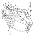
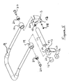
- FIGS 1 and 2 show a first example of a plate compactor 1.
- the compactor 1 is of the type conventionally known as a plate compactor.
- the compactor 1 includes a main body 2 on which is mounted a base plate 3.
- Mounted on the main body 2 is a motor 4.
- the output from the motor 4 drives a conventional vibration generating mechanism via a drive belt contained in a drive belt housing 5.
- Also attached to the main body 2 is a frame 6, which has two mounting assemblies 10 attached at the rear, upper corners 8 of the frame 6.
- the mounting assemblies 10 are used to mount a handle 9 on the frame 6. Interconnecting the mounting assemblies 10 is a weighted cross bar 11.
- the bar 11 typically has a weight of 5kg.
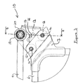
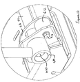
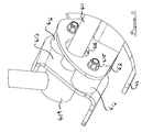
- FIGs 3 and 4 are enlarged side and perspective views respectively of section A of Figure 1. These figures show the mounting assemblies 10 in more detail.
- the mounting assemblies 10 each include two rubber bushes 12, a frame plate 7 and a handle mounting plate 13.
- the plates 7 are attached to the upper corners 8 of the frame 6, for example, by welding of the plates 7 to the upper corners of the frame 6.
- the plates 7, 13 are attached to opposite sides of the rubber bushes 12 by bolts 14 and nuts 15.
- the plate 7 has a flange 16 that engages in a slot 17 in the plate 13. This limits movement of the plate 13 relative to the plate 7 and so limits shear and twisting stresses on the bushes 12.
- the handle is generally U-shaped with the central section of the handle 9 forming a grip section 30.
- the ends 19 of the handle 9 are attached to the opposite ends of the bar 11 by bolts 20 that pass through bushings 21 located in the handle ends 19 and holes 22 in the plates 13 and engage with threaded bores 23 in the ends of the bar 11, as shown in Figure 5.
- Figure 5 also shows that the bushes 12 each include a threaded stud 27 that enables the bushes 12 to be attached to the plates 13 by means of a nut 15.
- Figure 6 shows how the bushes 12 attach to the plates 7 by means of bolts 14 that engage with threaded bores 25 in the bushes 12.
- Figure 7 is a cross-section that shows the bushes attached to the plates 7, 13 and the bar 11 and handle ends 19 pivotally coupled to the plates 13.
- the handle 9 is pivoted back about the pivot connection with the plates 13 until the grip section 30 of the handle is behind the mounting assemblies 10. Backward pivoting of the handle 9 is limited by stop 18 on the plates 13.
- the compactor 1 can be used by an operator, who holds the grip section 30 of the handle 9.
- the presence of the rubber bushes 12 helps to mechanically isolate vibration of the compactor main body 2 from the handle 9.
- the vibration is further reduced by the weight in the form of the cross-bar 11 that interconnects ends 19 of the handle 9.
- the bar 11 helps to increase the rigidity of the handle 9. As the bar 11 is concentric with the pivoting point of the handle 9, an operator is not fatigued by having to lift the weight of the bar 11 on the handle as the weight of the bar 11 is balanced on the handle 9.
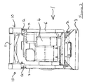
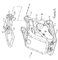
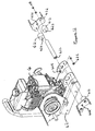
- FIGS 8 and 9 show a second example of a plate compactor 41.
- the compactor 41 is also of the type conventionally known as a plate compactor and is generally similar in basic construction and operation to the compactor 1 described above.
- the compactor 41 includes a main body 42 on which is mounted a base plate 43.
- Mounted on the main body 42 is a motor 44.
- the output from the motor 44 drives a conventional vibration generating mechanism via a drive belt contained in a drive belt housing 45.
- Mounted on the rear of the main body 42 are two mounting assemblies 410.
- the mounting assemblies 410 are used to mount a handle 49 on the main body 42. Interconnecting the mounting assemblies 410 is a weighted cross bar 411.
- the bar 411 typically has a weight of 5kg.
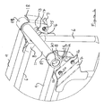
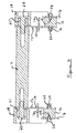
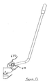
- FIGs 10 and 11 show the mounting assemblies 410 in more detail and Figure 12 shows an exploded view of the mounting assemblies 410 and the cross bar 411.
- the mounting assemblies 410 each include two rubber bushes 412, a main body plate 47 and a handle mounting plate 413.
- the plates 47, 413 are attached to opposite sides of the rubber bushes 412 by bolts 414 and nuts 415.
- the plate 47 has an aperture 416 through which the bar 411 extends.
- the aperture 416 is of a size such that flexing of the rubber bushes 412 is permitted but limits movement of the bar 411 and therefore, plate 413 relative to the plate 47 so that excessive shear and twisting stresses are not applied to the rubber bushes 412.
- Pivotally mounted on the plates 413 are respective ends 419 of the handle 49.
- the ends 419 of the handle 49 are attached to the opposite ends of the bar 411 by bolts 420 that pass through bushings 421 located in the handle ends 419 and holes 422 in the plates 413 and engage with threaded bores 423 in the ends of the bar 411, as shown in Figure 12.
- Figure 12 also shows that the bushes 412 each include a threaded stud 427 that enables the bushes 412 to be attached to the plates 47 by means of a nut 415.
- the bushes 412 attach to the plates 413 by means of bolts 414 that engage with threaded bores (not shown) in the bushes 412.
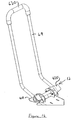
- the handle 49 In use, the handle 49 is stored in the position shown in Figure 8 where the handle rests against forward stop 435 on the plates 413. To operate the compactor 41 the handle 49 is pivoted back about the pivot connection with the plates 413 until grip section 430 of the handle is behind the mounting assemblies 410, as shown in Figures 13 and 14. Backward pivoting of the handle 49 is limited by stop 418 on the plates 413. When the motor 44 is started the compactor 41 can be used by an operator, who holds the grip section 430 of the handle 49.
- the presence of the rubber bushes 412 helps to mechanically isolate vibration of the compactor main body 42 from the handle 49.
- the vibration is further reduced by the weight in the form of the cross-bar 411 that interconnects ends 419 of the handle 49.
- the bar 411 helps to increase the rigidity of the handle 49. As the bar 411 is concentric with the pivoting point of the handle 49, an operator is not fatigued by having to lift the weight of the bar 411 on the handle, as the weight of the bar 411 is balanced on the handle 49.
- the plate compactors 1, 41 are particularly useful for compaction of ground material, especially where the ground material is: (i) a granular material, such as gravel, soil, sand, hardcore or other aggregates; and/or (ii) a paving material, such as paving block, paving slab flagstones or asphalt.
- the compactors can also be used for other applications that require a downward force to be exerted on a surface, such as during the installation of waterproof membranes on a surface.
- An advantage of the invention is that by reducing vibration of the handles of the compactor, the vibration experienced by an operator is also reduced and this helps to prolong the period that an operator can safely use the compactors 1, 41 without suffering from VWF without affecting the efficiency of the compactors 1, 41.
Landscapes
- Engineering & Computer Science (AREA)
- Structural Engineering (AREA)
- Civil Engineering (AREA)
- Life Sciences & Earth Sciences (AREA)
- Environmental & Geological Engineering (AREA)
- Soil Sciences (AREA)
- General Life Sciences & Earth Sciences (AREA)
- Mining & Mineral Resources (AREA)
- Paleontology (AREA)
- Agronomy & Crop Science (AREA)
- General Engineering & Computer Science (AREA)
- Architecture (AREA)
- Mechanical Engineering (AREA)
- Road Paving Machines (AREA)
- Dry Formation Of Fiberboard And The Like (AREA)
Priority Applications (1)
| Application Number | Priority Date | Filing Date | Title |
|---|---|---|---|
| PL05250279T PL1557495T3 (pl) | 2004-01-23 | 2005-01-20 | Ubijak |
Applications Claiming Priority (2)
| Application Number | Priority Date | Filing Date | Title |
|---|---|---|---|
| GB0401421 | 2004-01-23 | ||
| GBGB0401421.3A GB0401421D0 (en) | 2004-01-23 | 2004-01-23 | A compactor |
Publications (3)
| Publication Number | Publication Date |
|---|---|
| EP1557495A2 true EP1557495A2 (de) | 2005-07-27 |
| EP1557495A3 EP1557495A3 (de) | 2007-07-18 |
| EP1557495B1 EP1557495B1 (de) | 2011-06-22 |
Family
ID=31971298
Family Applications (1)
| Application Number | Title | Priority Date | Filing Date |
|---|---|---|---|
| EP05250279A Expired - Lifetime EP1557495B1 (de) | 2004-01-23 | 2005-01-20 | Verdichtungsgerät |
Country Status (4)
| Country | Link |
|---|---|
| EP (1) | EP1557495B1 (de) |
| AT (1) | ATE513950T1 (de) |
| GB (2) | GB0401421D0 (de) |
| PL (1) | PL1557495T3 (de) |
Cited By (1)
| Publication number | Priority date | Publication date | Assignee | Title |
|---|---|---|---|---|
| DE202009000264U1 (de) | 2008-02-01 | 2009-03-26 | Ammann Verdichtung Gmbh | Dämpfungselement |
Family Cites Families (4)
| Publication number | Priority date | Publication date | Assignee | Title |
|---|---|---|---|---|
| BE654553A (de) * | 1963-10-19 | |||
| US4113403A (en) * | 1977-08-31 | 1978-09-12 | Stone Construction Equipment Inc. | Plate type compactor |
| GB2356235A (en) * | 1999-11-13 | 2001-05-16 | Benford Ltd | Compactor machine |
| DE10007869C1 (de) * | 2000-02-21 | 2001-08-23 | Ammann Verdichtung Gmbh | Vibrationsplatte |
-
2004
- 2004-01-23 GB GBGB0401421.3A patent/GB0401421D0/en not_active Ceased
-
2005
- 2005-01-20 EP EP05250279A patent/EP1557495B1/de not_active Expired - Lifetime
- 2005-01-20 PL PL05250279T patent/PL1557495T3/pl unknown
- 2005-01-20 AT AT05250279T patent/ATE513950T1/de not_active IP Right Cessation
- 2005-01-20 GB GB0501291A patent/GB2410284B/en not_active Expired - Lifetime
Cited By (1)
| Publication number | Priority date | Publication date | Assignee | Title |
|---|---|---|---|---|
| DE202009000264U1 (de) | 2008-02-01 | 2009-03-26 | Ammann Verdichtung Gmbh | Dämpfungselement |
Also Published As
| Publication number | Publication date |
|---|---|
| EP1557495A3 (de) | 2007-07-18 |
| PL1557495T3 (pl) | 2011-12-30 |
| ATE513950T1 (de) | 2011-07-15 |
| GB0501291D0 (en) | 2005-03-02 |
| GB0401421D0 (en) | 2004-02-25 |
| EP1557495B1 (de) | 2011-06-22 |
| GB2410284B (en) | 2009-05-20 |
| GB2410284A (en) | 2005-07-27 |
Similar Documents
| Publication | Publication Date | Title |
|---|---|---|
| US9316343B2 (en) | Portable concrete molding machine | |
| EP1099797B1 (de) | Verdichtungsgerät | |
| US6200065B1 (en) | Lightweight, portable vibratory screed | |
| US20090035065A1 (en) | Compactor | |
| EP1561882B1 (de) | Bewegbarer Vibrationsstampfer mit Vibrationsbeschränkungssystem | |
| GB2455627A (en) | Electric compactor | |
| US4170427A (en) | Vibrating tamper | |
| CN221545201U (zh) | 板式压实机 | |
| WO2020202585A1 (ja) | 地固め装置 | |
| EP1557495A2 (de) | Verdichtungsgerät | |
| CN111501491A (zh) | 一种附着式振动装置及摊铺机 | |
| US3336848A (en) | Material compactor | |
| US12098518B2 (en) | Vibration ripper having link structure with improved vibration isolating function | |
| JP3635389B2 (ja) | 振動板装置 | |
| US5236279A (en) | Self-propelled concrete tamping apparatus | |
| CA1144210A (en) | Compact resonance drive for earth-working equipment | |
| JP4204638B2 (ja) | アスファルトフィニッシャー | |
| JPWO2020202585A1 (ja) | 地固め装置 | |
| CN204780543U (zh) | 带马达的双振捣机构、熨平板及摊铺机 | |
| KR102004443B1 (ko) | 다짐성능이 향상된 타이템퍼 | |
| CA3121796C (en) | Vibration ripper having link structure with improved vibration isolating function | |
| JPH0516246Y2 (de) | ||
| JP2007239398A (ja) | アスファルトフィニッシャー | |
| CZ8744U1 (cs) | Vibrační deska | |
| JP2002356809A (ja) | 自走締め固め機 |
Legal Events
| Date | Code | Title | Description |
|---|---|---|---|
| PUAI | Public reference made under article 153(3) epc to a published international application that has entered the european phase |
Free format text: ORIGINAL CODE: 0009012 |
|
| AK | Designated contracting states |
Kind code of ref document: A2 Designated state(s): AT BE BG CH CY CZ DE DK EE ES FI FR GB GR HU IE IS IT LI LT LU MC NL PL PT RO SE SI SK TR |
|
| AX | Request for extension of the european patent |
Extension state: AL BA HR LV MK YU |
|
| PUAL | Search report despatched |
Free format text: ORIGINAL CODE: 0009013 |
|
| AK | Designated contracting states |
Kind code of ref document: A3 Designated state(s): AT BE BG CH CY CZ DE DK EE ES FI FR GB GR HU IE IS IT LI LT LU MC NL PL PT RO SE SI SK TR |
|
| AX | Request for extension of the european patent |
Extension state: AL BA HR LV MK YU |
|
| RIC1 | Information provided on ipc code assigned before grant |
Ipc: E01C 19/38 20060101ALI20070612BHEP Ipc: E02D 3/074 20060101AFI20050425BHEP Ipc: B25D 17/04 20060101ALI20070612BHEP |
|
| 17P | Request for examination filed |
Effective date: 20080118 |
|
| AKX | Designation fees paid |
Designated state(s): AT BE BG CH CY CZ DE DK EE ES FI FR GB GR HU IE IS IT LI LT LU MC NL PL PT RO SE SI SK TR |
|
| GRAJ | Information related to disapproval of communication of intention to grant by the applicant or resumption of examination proceedings by the epo deleted |
Free format text: ORIGINAL CODE: EPIDOSDIGR1 |
|
| GRAP | Despatch of communication of intention to grant a patent |
Free format text: ORIGINAL CODE: EPIDOSNIGR1 |
|
| GRAP | Despatch of communication of intention to grant a patent |
Free format text: ORIGINAL CODE: EPIDOSNIGR1 |
|
| RBV | Designated contracting states (corrected) |
Designated state(s): AT BE BG CH CY CZ DE DK EE ES FI FR GR HU IE IS IT LI LT LU MC NL PL PT RO SE SI SK TR |
|
| GRAS | Grant fee paid |
Free format text: ORIGINAL CODE: EPIDOSNIGR3 |
|
| GRAA | (expected) grant |
Free format text: ORIGINAL CODE: 0009210 |
|
| AK | Designated contracting states |
Kind code of ref document: B1 Designated state(s): AT BE BG CH CY CZ DE DK EE ES FI FR GR HU IE IS IT LI LT LU MC NL PL PT RO SE SI SK TR |
|
| REG | Reference to a national code |
Ref country code: CH Ref legal event code: EP |
|
| REG | Reference to a national code |
Ref country code: IE Ref legal event code: FG4D |
|
| REG | Reference to a national code |
Ref country code: DE Ref legal event code: R096 Ref document number: 602005028615 Country of ref document: DE Effective date: 20110811 |
|
| REG | Reference to a national code |
Ref country code: NL Ref legal event code: VDEP Effective date: 20110622 |
|
| PG25 | Lapsed in a contracting state [announced via postgrant information from national office to epo] |
Ref country code: SE Free format text: LAPSE BECAUSE OF FAILURE TO SUBMIT A TRANSLATION OF THE DESCRIPTION OR TO PAY THE FEE WITHIN THE PRESCRIBED TIME-LIMIT Effective date: 20110622 Ref country code: LT Free format text: LAPSE BECAUSE OF FAILURE TO SUBMIT A TRANSLATION OF THE DESCRIPTION OR TO PAY THE FEE WITHIN THE PRESCRIBED TIME-LIMIT Effective date: 20110622 |
|
| PG25 | Lapsed in a contracting state [announced via postgrant information from national office to epo] |
Ref country code: CY Free format text: LAPSE BECAUSE OF FAILURE TO SUBMIT A TRANSLATION OF THE DESCRIPTION OR TO PAY THE FEE WITHIN THE PRESCRIBED TIME-LIMIT Effective date: 20110622 Ref country code: GR Free format text: LAPSE BECAUSE OF FAILURE TO SUBMIT A TRANSLATION OF THE DESCRIPTION OR TO PAY THE FEE WITHIN THE PRESCRIBED TIME-LIMIT Effective date: 20110923 Ref country code: AT Free format text: LAPSE BECAUSE OF FAILURE TO SUBMIT A TRANSLATION OF THE DESCRIPTION OR TO PAY THE FEE WITHIN THE PRESCRIBED TIME-LIMIT Effective date: 20110622 Ref country code: FI Free format text: LAPSE BECAUSE OF FAILURE TO SUBMIT A TRANSLATION OF THE DESCRIPTION OR TO PAY THE FEE WITHIN THE PRESCRIBED TIME-LIMIT Effective date: 20110622 Ref country code: SI Free format text: LAPSE BECAUSE OF FAILURE TO SUBMIT A TRANSLATION OF THE DESCRIPTION OR TO PAY THE FEE WITHIN THE PRESCRIBED TIME-LIMIT Effective date: 20110622 |
|
| PG25 | Lapsed in a contracting state [announced via postgrant information from national office to epo] |
Ref country code: NL Free format text: LAPSE BECAUSE OF FAILURE TO SUBMIT A TRANSLATION OF THE DESCRIPTION OR TO PAY THE FEE WITHIN THE PRESCRIBED TIME-LIMIT Effective date: 20110622 Ref country code: BE Free format text: LAPSE BECAUSE OF FAILURE TO SUBMIT A TRANSLATION OF THE DESCRIPTION OR TO PAY THE FEE WITHIN THE PRESCRIBED TIME-LIMIT Effective date: 20110622 |
|
| REG | Reference to a national code |
Ref country code: PL Ref legal event code: T3 |
|
| PG25 | Lapsed in a contracting state [announced via postgrant information from national office to epo] |
Ref country code: CZ Free format text: LAPSE BECAUSE OF FAILURE TO SUBMIT A TRANSLATION OF THE DESCRIPTION OR TO PAY THE FEE WITHIN THE PRESCRIBED TIME-LIMIT Effective date: 20110622 Ref country code: PT Free format text: LAPSE BECAUSE OF FAILURE TO SUBMIT A TRANSLATION OF THE DESCRIPTION OR TO PAY THE FEE WITHIN THE PRESCRIBED TIME-LIMIT Effective date: 20111024 Ref country code: IS Free format text: LAPSE BECAUSE OF FAILURE TO SUBMIT A TRANSLATION OF THE DESCRIPTION OR TO PAY THE FEE WITHIN THE PRESCRIBED TIME-LIMIT Effective date: 20111022 Ref country code: EE Free format text: LAPSE BECAUSE OF FAILURE TO SUBMIT A TRANSLATION OF THE DESCRIPTION OR TO PAY THE FEE WITHIN THE PRESCRIBED TIME-LIMIT Effective date: 20110622 |
|
| PG25 | Lapsed in a contracting state [announced via postgrant information from national office to epo] |
Ref country code: RO Free format text: LAPSE BECAUSE OF FAILURE TO SUBMIT A TRANSLATION OF THE DESCRIPTION OR TO PAY THE FEE WITHIN THE PRESCRIBED TIME-LIMIT Effective date: 20110622 Ref country code: SK Free format text: LAPSE BECAUSE OF FAILURE TO SUBMIT A TRANSLATION OF THE DESCRIPTION OR TO PAY THE FEE WITHIN THE PRESCRIBED TIME-LIMIT Effective date: 20110622 |
|
| PLBE | No opposition filed within time limit |
Free format text: ORIGINAL CODE: 0009261 |
|
| STAA | Information on the status of an ep patent application or granted ep patent |
Free format text: STATUS: NO OPPOSITION FILED WITHIN TIME LIMIT |
|
| 26N | No opposition filed |
Effective date: 20120323 |
|
| PG25 | Lapsed in a contracting state [announced via postgrant information from national office to epo] |
Ref country code: IT Free format text: LAPSE BECAUSE OF FAILURE TO SUBMIT A TRANSLATION OF THE DESCRIPTION OR TO PAY THE FEE WITHIN THE PRESCRIBED TIME-LIMIT Effective date: 20110622 |
|
| PG25 | Lapsed in a contracting state [announced via postgrant information from national office to epo] |
Ref country code: DK Free format text: LAPSE BECAUSE OF FAILURE TO SUBMIT A TRANSLATION OF THE DESCRIPTION OR TO PAY THE FEE WITHIN THE PRESCRIBED TIME-LIMIT Effective date: 20110622 |
|
| REG | Reference to a national code |
Ref country code: DE Ref legal event code: R097 Ref document number: 602005028615 Country of ref document: DE Effective date: 20120323 |
|
| PG25 | Lapsed in a contracting state [announced via postgrant information from national office to epo] |
Ref country code: MC Free format text: LAPSE BECAUSE OF NON-PAYMENT OF DUE FEES Effective date: 20120131 |
|
| REG | Reference to a national code |
Ref country code: CH Ref legal event code: PL |
|
| REG | Reference to a national code |
Ref country code: IE Ref legal event code: MM4A |
|
| PG25 | Lapsed in a contracting state [announced via postgrant information from national office to epo] |
Ref country code: LI Free format text: LAPSE BECAUSE OF NON-PAYMENT OF DUE FEES Effective date: 20120131 Ref country code: CH Free format text: LAPSE BECAUSE OF NON-PAYMENT OF DUE FEES Effective date: 20120131 |
|
| PG25 | Lapsed in a contracting state [announced via postgrant information from national office to epo] |
Ref country code: IE Free format text: LAPSE BECAUSE OF NON-PAYMENT OF DUE FEES Effective date: 20120120 |
|
| PG25 | Lapsed in a contracting state [announced via postgrant information from national office to epo] |
Ref country code: ES Free format text: LAPSE BECAUSE OF FAILURE TO SUBMIT A TRANSLATION OF THE DESCRIPTION OR TO PAY THE FEE WITHIN THE PRESCRIBED TIME-LIMIT Effective date: 20111003 |
|
| PG25 | Lapsed in a contracting state [announced via postgrant information from national office to epo] |
Ref country code: BG Free format text: LAPSE BECAUSE OF FAILURE TO SUBMIT A TRANSLATION OF THE DESCRIPTION OR TO PAY THE FEE WITHIN THE PRESCRIBED TIME-LIMIT Effective date: 20110922 |
|
| PG25 | Lapsed in a contracting state [announced via postgrant information from national office to epo] |
Ref country code: TR Free format text: LAPSE BECAUSE OF FAILURE TO SUBMIT A TRANSLATION OF THE DESCRIPTION OR TO PAY THE FEE WITHIN THE PRESCRIBED TIME-LIMIT Effective date: 20110622 |
|
| PG25 | Lapsed in a contracting state [announced via postgrant information from national office to epo] |
Ref country code: LU Free format text: LAPSE BECAUSE OF NON-PAYMENT OF DUE FEES Effective date: 20120120 |
|
| PG25 | Lapsed in a contracting state [announced via postgrant information from national office to epo] |
Ref country code: HU Free format text: LAPSE BECAUSE OF FAILURE TO SUBMIT A TRANSLATION OF THE DESCRIPTION OR TO PAY THE FEE WITHIN THE PRESCRIBED TIME-LIMIT Effective date: 20050120 |
|
| REG | Reference to a national code |
Ref country code: FR Ref legal event code: PLFP Year of fee payment: 12 |
|
| REG | Reference to a national code |
Ref country code: FR Ref legal event code: PLFP Year of fee payment: 13 |
|
| REG | Reference to a national code |
Ref country code: FR Ref legal event code: PLFP Year of fee payment: 14 |
|
| PGFP | Annual fee paid to national office [announced via postgrant information from national office to epo] |
Ref country code: DE Payment date: 20240227 Year of fee payment: 20 |
|
| PGFP | Annual fee paid to national office [announced via postgrant information from national office to epo] |
Ref country code: PL Payment date: 20240228 Year of fee payment: 20 Ref country code: FR Payment date: 20240227 Year of fee payment: 20 |
|
| REG | Reference to a national code |
Ref country code: DE Ref legal event code: R071 Ref document number: 602005028615 Country of ref document: DE |