EP1557237A2 - Werkzeugmaschine mit einem hydrostatischen Gleitfilm - Google Patents
Werkzeugmaschine mit einem hydrostatischen Gleitfilm Download PDFInfo
- Publication number
- EP1557237A2 EP1557237A2 EP05000976A EP05000976A EP1557237A2 EP 1557237 A2 EP1557237 A2 EP 1557237A2 EP 05000976 A EP05000976 A EP 05000976A EP 05000976 A EP05000976 A EP 05000976A EP 1557237 A2 EP1557237 A2 EP 1557237A2
- Authority
- EP
- European Patent Office
- Prior art keywords
- machine tool
- tool according
- guide surface
- base
- foot
- Prior art date
- Legal status (The legal status is an assumption and is not a legal conclusion. Google has not performed a legal analysis and makes no representation as to the accuracy of the status listed.)
- Ceased
Links
Images


Classifications
-
- F—MECHANICAL ENGINEERING; LIGHTING; HEATING; WEAPONS; BLASTING
- F16—ENGINEERING ELEMENTS AND UNITS; GENERAL MEASURES FOR PRODUCING AND MAINTAINING EFFECTIVE FUNCTIONING OF MACHINES OR INSTALLATIONS; THERMAL INSULATION IN GENERAL
- F16C—SHAFTS; FLEXIBLE SHAFTS; ELEMENTS OR CRANKSHAFT MECHANISMS; ROTARY BODIES OTHER THAN GEARING ELEMENTS; BEARINGS
- F16C29/00—Bearings for parts moving only linearly
- F16C29/12—Arrangements for adjusting play
-
- B—PERFORMING OPERATIONS; TRANSPORTING
- B23—MACHINE TOOLS; METAL-WORKING NOT OTHERWISE PROVIDED FOR
- B23Q—DETAILS, COMPONENTS, OR ACCESSORIES FOR MACHINE TOOLS, e.g. ARRANGEMENTS FOR COPYING OR CONTROLLING; MACHINE TOOLS IN GENERAL CHARACTERISED BY THE CONSTRUCTION OF PARTICULAR DETAILS OR COMPONENTS; COMBINATIONS OR ASSOCIATIONS OF METAL-WORKING MACHINES, NOT DIRECTED TO A PARTICULAR RESULT
- B23Q1/00—Members which are comprised in the general build-up of a form of machine, particularly relatively large fixed members
- B23Q1/25—Movable or adjustable work or tool supports
- B23Q1/26—Movable or adjustable work or tool supports characterised by constructional features relating to the co-operation of relatively movable members; Means for preventing relative movement of such members
- B23Q1/38—Movable or adjustable work or tool supports characterised by constructional features relating to the co-operation of relatively movable members; Means for preventing relative movement of such members using fluid bearings or fluid cushion supports
- B23Q1/385—Movable or adjustable work or tool supports characterised by constructional features relating to the co-operation of relatively movable members; Means for preventing relative movement of such members using fluid bearings or fluid cushion supports in which the thickness of the fluid-layer is adjustable
-
- B—PERFORMING OPERATIONS; TRANSPORTING
- B23—MACHINE TOOLS; METAL-WORKING NOT OTHERWISE PROVIDED FOR
- B23Q—DETAILS, COMPONENTS, OR ACCESSORIES FOR MACHINE TOOLS, e.g. ARRANGEMENTS FOR COPYING OR CONTROLLING; MACHINE TOOLS IN GENERAL CHARACTERISED BY THE CONSTRUCTION OF PARTICULAR DETAILS OR COMPONENTS; COMBINATIONS OR ASSOCIATIONS OF METAL-WORKING MACHINES, NOT DIRECTED TO A PARTICULAR RESULT
- B23Q1/00—Members which are comprised in the general build-up of a form of machine, particularly relatively large fixed members
- B23Q1/25—Movable or adjustable work or tool supports
- B23Q1/44—Movable or adjustable work or tool supports using particular mechanisms
- B23Q1/56—Movable or adjustable work or tool supports using particular mechanisms with sliding pairs only, the sliding pairs being the first two elements of the mechanism
- B23Q1/60—Movable or adjustable work or tool supports using particular mechanisms with sliding pairs only, the sliding pairs being the first two elements of the mechanism two sliding pairs only, the sliding pairs being the first two elements of the mechanism
- B23Q1/62—Movable or adjustable work or tool supports using particular mechanisms with sliding pairs only, the sliding pairs being the first two elements of the mechanism two sliding pairs only, the sliding pairs being the first two elements of the mechanism with perpendicular axes, e.g. cross-slides
- B23Q1/621—Movable or adjustable work or tool supports using particular mechanisms with sliding pairs only, the sliding pairs being the first two elements of the mechanism two sliding pairs only, the sliding pairs being the first two elements of the mechanism with perpendicular axes, e.g. cross-slides a single sliding pair followed perpendicularly by a single sliding pair
-
- F—MECHANICAL ENGINEERING; LIGHTING; HEATING; WEAPONS; BLASTING
- F16—ENGINEERING ELEMENTS AND UNITS; GENERAL MEASURES FOR PRODUCING AND MAINTAINING EFFECTIVE FUNCTIONING OF MACHINES OR INSTALLATIONS; THERMAL INSULATION IN GENERAL
- F16C—SHAFTS; FLEXIBLE SHAFTS; ELEMENTS OR CRANKSHAFT MECHANISMS; ROTARY BODIES OTHER THAN GEARING ELEMENTS; BEARINGS
- F16C32/00—Bearings not otherwise provided for
- F16C32/06—Bearings not otherwise provided for with moving member supported by a fluid cushion formed, at least to a large extent, otherwise than by movement of the shaft, e.g. hydrostatic air-cushion bearings
- F16C32/0662—Details of hydrostatic bearings independent of fluid supply or direction of load
- F16C32/067—Details of hydrostatic bearings independent of fluid supply or direction of load of bearings adjustable for aligning, positioning, wear or play
- F16C32/0674—Details of hydrostatic bearings independent of fluid supply or direction of load of bearings adjustable for aligning, positioning, wear or play by means of pre-load on the fluid bearings
-
- F—MECHANICAL ENGINEERING; LIGHTING; HEATING; WEAPONS; BLASTING
- F16—ENGINEERING ELEMENTS AND UNITS; GENERAL MEASURES FOR PRODUCING AND MAINTAINING EFFECTIVE FUNCTIONING OF MACHINES OR INSTALLATIONS; THERMAL INSULATION IN GENERAL
- F16C—SHAFTS; FLEXIBLE SHAFTS; ELEMENTS OR CRANKSHAFT MECHANISMS; ROTARY BODIES OTHER THAN GEARING ELEMENTS; BEARINGS
- F16C2322/00—Apparatus used in shaping articles
- F16C2322/39—General buildup of machine tools, e.g. spindles, slides, actuators
Definitions
- the invention relates to a machine tool comprising a machine frame, one opposite the machine frame at least in a two-dimensional Movement plane movable processing unit and a guide device for guiding the processing unit in the two-dimensional Movement plane with a base guide surface having a guide base and with a processing unit supporting the foot element, which Having a base guide surface facing foot guide surface.
- the invention is therefore based on the object, a machine tool of generic type to improve such that the guide device as easy as possible to produce.
- the advantage of the solution according to the invention is the fact that such a Hydrostatic lubricating film due to its properties a precise Guiding the foot element over the guide base guaranteed and the other still offers the advantage of high damping.
- the extension of the base guide surface at least 1.5 times the maximum extent of the foot guide surface in the respective direction.
- the base guide surface With regard to the execution of the base guide surface so far no details provided. So it would be conceivable, the base guide surface to assemble several subareas.
- the base guide surface is recess-free is formed coherently, so that any kind of Recesses or depressions in the base guide surface are missing and Consequently, the base guide surface a continuous and smooth running represents contiguous area.
- the foot member with at least one feed for a hydrostatic lubricating film forming sliding medium is provided.
- the foot element with at least three feeds for the sliding medium are provided.
- the feeds for the sliding medium can be in a central region of the Be arranged foot element. Particularly stable is the foot element However, lead when the feeders for the sliding medium in an outboard Area of the foot guide surface are arranged.
- the at least one Sliding fluid supply means for adjusting a Inflow amount of the sliding medium is assigned.
- the adjustment of the film thickness of the hydrostatic takes place Sliding film such that this one an immediate resting of the foot guide surface lift-off force counteracting the base guide surface generated, which is constantly effective and thus during operation of the inventive machine tool resting on the foot guide surface prevented on the base guide surface.
- the hydrostatic sliding film is formed so that the Lifting force compensates for a hold-down force acting on the foot element, which at least one perpendicular to the base guide surface Component of the weight of the processing unit includes.
- the hydrostatic sliding film behaves such that the lifting force by non-destructive compression of the hydrostatic sliding film so far it is enlargeable that with the lifting force all, in a processing a workpiece occurring hold-down forces are compensated.
- hydrostatic sliding film is free of machining State is acted upon by such a large hold-down force that the increase in the hold-down force when machining the workpiece to a reduction the thickness of the hydrostatic sliding film by about 50% or less, better still about 30% or less and especially cheap by about 15% or less.
- Such a holding device could in principle be a mechanical holding device be, which on the one hand engages the machine frame and on the other hand, the processing unit and / or the foot element acted upon.
- the holding device acts without contact between the guide base and the foot element.
- Such a non-contact effect can be, for example, characterized achieve that the holding device between the guide base and the foot element generates a negative pressure cushion, which the foot element in the direction the management base acted upon.
- the vacuum pad by a recess in the foot element with respect to its expansion in Direction of the base guide surface and the foot guide surface is fixed.
- FIG. 1 Another embodiment of a holding device according to the invention sees in that the holding device additionally or alternatively to the provision of Vacuum cushion the attractions by magnetic attraction generated.
- Such magnetic attraction can be either provided by Permanent magnets reach or by the fact that the holding device comprises at least one electromagnet which the magnetic field generated.
- Such an electromagnet could for example be in the foot element or in the guide base provided electromagnet, which is a on the guide base or the foot element acting magnetic field for generating the attraction generated.
- Such an electromagnet has the advantage that generated by this Magnetic field controllable and thus the desired attractive force adjustable is.
- a particularly favorable solution for generating a magnetic attraction between the guide base and the foot element provides that the holding device has at least one primary part and at least one secondary part, one in the guide base and the other in the foot element is arranged.
- the at least one secondary part is in the foot element is arranged and the at least one primary part in the guide base, so that there is no need to control the primary part in the moving system, but in relation to the machine frame stationary part of the guide device.
- the secondary part is constructed so that there are several Pole elements includes.
- the individual pole elements of the secondary part can either by Permanent magnets or short-circuit windings can be realized.
- the primary part a plurality of pole elements usually by Bestrombare windings with Polschuhköpfen are realized.
- pole elements which act directly on the secondary part, to energize, preferably the pole elements are individually controlled.
- the processing unit and the foot element by a drive device in the two-dimensional plane of motion are movable.
- Such a drive device can in different ways be executed.
- the drive device is two-dimensional effective stab kinematic drive is formed.
- Such a kinematic drive can in various ways and Be realized way.
- stab kinematic drive has articulated mounted and variable length drive struts.
- Another embodiment provides that the kinematic drive articulated length invariant, however, on a linear guide with Carriage has relative to each other movable drive struts.
- Another way to realize the drive device provides that the at least one primary part and at least one secondary part having Holding device is operable as a linear drive of the drive device.
- the drive means could be designed so that they move in one direction through the primary and secondary parts formed linear drive and to move in a direction across this rod kinematic elements uses.
- the pole elements of the secondary part and the primary part form a checkerboard, as for example in the German Patent application DE 102 67 796.1-14 is described.
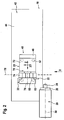
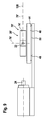
- a first embodiment of a machine tool according to the invention shown in Fig. 1, comprises a machine frame 10, opposite which a as a whole with 20 designated processing unit in a through two transverse mutually extending directions of movement, for example, the directions of movement X and Z, defined movement plane is movable, for example around with borne by the processing unit 20 processing tools 22 to edit a workpiece 24. But it is also conceivable with the processing unit 20 to position a workpiece.
- the workpiece 24 is for example in the first embodiment in a Workpiece holder 26 a workpiece spindle 28 is held and by means of Workpiece spindle 28 rotatable about a spindle axis 30, so that with the machining tools 22 performed, for example, a turning can be, alternatively or additionally but also a milling, for which the workpiece 24 about the spindle axis 30 in defined rotational positions can be brought and set in these.
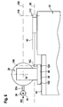
- the guide means 40 comprises a foot member 46 on which the Machining unit 20 is arranged and which a foot guide surface 48th facing the base guide surface 44 and, as shown in FIG. 3, via a hydrostatic sliding film 50 on the base guide surface 44 is supported and guided at a precisely defined distance from this.
- the guide device 40 For constructing the hydrostatic sliding film 50, the guide device 40, as shown in Fig. 1 to 3, provided with a plurality of feeders 52, via which the hydrostatic sliding film 50 with the same for training required sliding medium is supplied.
- the feeders 52 are, for example, as compared to the réelle arrangements character 48 set back provided in the foot member 46 pockets 54, which is supplied via a supply line 56, the sliding medium, wherein through the pockets 54 in this flowing in the sliding medium along in essentially in all directions parallel to the base guide surface 44 extending Flow directions 58 flows and thus on all sides of the each feed 52 exits and the hydrostatic lubricating film 50 between the base guide surface 44 and the foot guide surface 48 is maintained.
- the Amount of about the supply line 56, the pockets 54 of the feeders 52nd supplied lubricating medium can be preferably via a in the Control supply line 56 control valve 60 provided control.
- the sliding medium of the supply line 56 by as a whole with 62 supplied supply device, wherein the supply device 62 represents a pumping device in the simplest case, which is the Sliding medium with that necessary for the construction of the hydrostatic sliding film 50 Pressure into a supply line system 64, from which then the supply line 56 branches off.
- the supply device 62 represents a pumping device in the simplest case, which is the Sliding medium with that necessary for the construction of the hydrostatic sliding film 50 Pressure into a supply line system 64, from which then the supply line 56 branches off.
- the supply device 62 is designed so that they Sliding medium with a constant pressure in the supply line system 64th provides an adjustment of the control valve 60 as a throttle sufficient to maintain hydrostatic power at constant force ratios Sliding film 50 to produce with substantially constant film thickness, since In this case, the film thickness of the hydrostatic sliding film 50 automatically This regulates that a smaller distance between the base guide surface 44 and the foot guide surface 48 has a larger flow resistance in hydrostatic lubricating film 50 results so that the pressure in the pockets 54th rises and by this pressure increase the base guide surface 44 and the Foot guide surface 48 are pressed apart again and thus the original film thickness is restored.
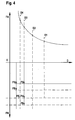
- the hydrostatic sliding film 50 thus creates one on the foot member 46 acting lifting force FA, which is directed perpendicular to the base guide surface 44 is, wherein this lifting force FA a perpendicular to the base guide surface 44th counteracts standing hold force FN, which consists of a vertical to the base guide surface 44 directed component of the weight FG and additional possibly even more perpendicular to the base guide surface 44 standing components FB on the processing unit 20 at the machining of the workpiece 24 acting forces composed.
- the hold-down force FN still includes the Component FB and consequently the lifting force FA must be the sum FG plus FB compensate, so that sets the film thickness D to the value D2, for example is about 70% of D1.
- the film thickness D of the hydrostatic sliding film 50 remains in any case obtained non-destructive, so that its sliding properties and damping properties essentially also preserved.
- a sensor 66 or more Provide sensors 66 to the foot member 46, which the distance between itself and the base guide surface 44 and thus also the distance determined between the base guide surface 44 and the foot guide surface 48. Due to the distance detected by the sensor 66 from the base guide surface 44 can thus via a controller 68 a corresponding control the control valve 60 for controlling the film thickness of the hydrostatic sliding film 50 done so that regardless of acting on the foot member 46 Hold down the film thickness of the hydrostatic sliding film 50 to a certain value is definable.
- the controller 68 with the sensor 66 either constantly in operation or at certain time intervals, to which with a variation of the Film thickness of the hydrostatic lubricating film 50 must be calculated activated to adjust the control valve 60 accordingly.
- the guide device 40 is basically the Possibility, the expansion of the base guide surface 44, by a multiple greater than the extension of the foot guide surface 48 to choose, the Basic guide surface 44 as continuous uninterrupted and recess-free designed surface formed so that at each point of the Base guide surface 44 of the hydrostatic lubricating film 50 between this and the Foot guide surface 48 can form.
- the extent of the base guide surface 44 is at least 1.5 times the maximum extent of the foot guide surface 48 in the Movement directions X, Z.
- Machine tool is the processing unit 20, for example, as a tool turret 70 formed, the turret housing 72 on the foot element 46 is arranged and which has a turret 74 which relative to Revolvergetude is rotatable about a turret axis 76.
- the turret axis runs 76 preferably approximately parallel to the base guide surface 44, so that the Turret 74 extends radially to the turret axis 76 in a plane 78, which then runs perpendicular to the base guide surface 44 in this case.
- the turret axis 76 is further aligned to approximately runs parallel to the spindle axis 30, the turret axis 76, however also include any angle with the spindle axis 30 or even vertically to the spindle axis 30 run.
- Turret 74 it would be possible to design the turret 74 as a star turret, more advantageous, however, due to the lower height, the formation of Turret 74 as a disc revolver, which thus on a the Revolvergeophuse 72 facing away from end face 80 with tool holders 82 for Recording the tools 22 can be fitted.
- This can be the radial Extension of the tools 22 relative to the turret axis 76 less hold than with a star turret and thus altogether the situation of the Revolverachse 76 relative to the base guide surface 44 hold lower than in the case a star turret.
- Moving the processing unit 20 with the foot member 46 relative to the guide base 42 can be done in a variety of ways.
- basically any type of displacement drive is suitable, which in is capable of, on one of the processing unit 20 side facing the Base guide surface 44, that is above the guide base 42 at the Machining unit 20 or the foot member 46 attack.
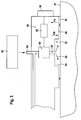
- drive means 90 which three Drive struts 92, 94, 96 which extends in a base guide surface 44th extend approximately parallel plane 98 and by a position control 100 for positioning the processing unit 20 on the guide base 42 are controllable.
- the drive struts 92, 94, 96 engage on the one hand, for example on the foot member 46 via joints 102, 104, 106 and are on the other hand, on the machine frame 10, as shown in Fig. 5, means Joints 112, 114, 116 stored.
- the drive struts 92, 94, 96 are preferably in the plane 98 so arranged that, for example, the drive struts 92 and 94 together Parallelogram form, so that can be ensured in a simple manner, that in all positions the alignment of the tools 22 parallel to the remaining positions.
- the drive means 90 is formed so that at least one of the drive struts 92, 94, 96, even better than the two Parallelogram cooperating drive struts 92, 94 on a the in Working position standing tool 22a opposite side of the processing unit 20 extend, so that a favorable support of the processing unit 20 against the occurring during the machining of the workpiece 24 Reaction forces RX in X-direction and RZ in Z-direction is possible.
- reaction forces RX and RZ act in one the spindle axis 30 cutting working plane 120, so that when the plane 98, in which the drive struts 92, 94, 96 extend deeper As the processing plane 120, the reaction forces RX and RZ on the Foot element 46 effect acting tilting moment, which thus to different Forces on the hydrostatic sliding film 50 leads, that is for example, the hydrostatic sliding film 50 in a working position standing tool 22a facing edge portion 122 of the foot member 46th load less than in this opposite edge region 124, which is therefore facing away from the standing in working position tool 22a.
- the level 98 ' in which the drive struts 92, 94, 96 extend to near the working plane 120 to lay down, preferably to lay so that this with the working plane 120 coincides, so that the reaction forces RX and RZ immediately can be received by the drive device 90 and no Tipping moment on the foot member 46 and thus to no uneven Loading the hydrostatic lubricating film 50 lead.
- hydrostatic lubricating film 50 substantially over the foot member 46 in essentially by a force FG contributing to the hold-down force FN, which is substantially perpendicular to the base guide surface 44th acting component of the weight of the processing unit 20 together corresponds to the foot member 46, wherein the force FG regardless of the Reaction forces RX and RZ is.
- the Drive device 90 ' also drive struts 92', 94 'and 96', however, the in this drive device 90 'are length invariant.
- the drive struts 92 ', 94' have such a length and the distance of the joints 102 and 104 and 112 and 114 is also identical, so that the Drive struts 92 'and 94' also form a parallelogram.
- the turret axis runs 76 of the tool turret 70 parallel or approximately parallel to the base guide surface 44, so that the turret 74 radially to the turret axis 76 always extends in a direction transverse to the base guide surface 44.
- FIGS. 9 and 10 In a fourth embodiment, shown in FIGS. 9 and 10 is the Tool turret 70 ', however, designed so that the turret 74' in the plane 78 'which extends parallel to the base guide surface 44, wherein in this case, the turret axis 76 'perpendicular or with a slight inclination is aligned with respect to a perpendicular to the base guide surface 44.
- the height of the processing unit 20 'and in particular the Distance of the working plane 120 of the base guide surface 44 worth mentioning reduce, so that due to the reaction forces RX and RZ occurring and on the processing unit 20 'acting tilting moment in the Processing of the workpiece 24 can also be reduced, whereby the hydrostatic sliding film 50 between the foot guide surface 48 and the base guide surface 44 is exposed to less fluctuations in power, even if the respective drive device 90 or 90 ', shown in connection with the first or third embodiment on the foot member 46th attacks.
- the fourth embodiment is either identical to the first one or the third embodiment, in particular with regard to the guide means 40, so that with respect to the not explicitly related Full content of the elements described with the fourth embodiment to these embodiments reference is made.
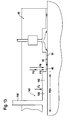
- a fifth embodiment of a machine tool according to the invention shown in Figs. 11, 12 and 13 are those features that are identical to those of the first embodiment, with the same Numeral provided so that with respect to the description of the same full content to the comments on the first embodiment reference can be taken.
- the holding device 140 operates without contact and generates in one Partial area between the base guide surface 44 and the foot guide surface 48th a vacuum pad 142, with a defined surface area FEX in Direction of the base guide surface 44 and the foot guide surface 48, so that a holding force corresponding to the negative pressure in the negative pressure cushion 142 FU is generated, which is perpendicular to the base guide surface 44th standing component of the weight FG added and consequently the hold-down force FN represents at least the sum of the force FU and the force FG, where appropriate, additional, when editing on the foot element 46 acting components FB contribute to the hold-down force FN.
- the vacuum pad 142 leaves with a defined surface area FEX
- FEX a vacuum line 146 opens, via the vacuum line 146 in the recess 144 of the negative pressure cushion 142 generating negative pressure
- the surface area FEX of the negative pressure pad corresponds 142 substantially the extent of the recess 144 in Direction parallel to the base guide surface 44th
- the vacuum pad 142 is arranged such that it surrounded by feeders 52 for sliding medium, and thus on all sides around the Vacuum pad 142 around the sliding film 50 provides a seal.
- Such a holding device 140 thus offers, as also shown in Fig. 4, the possibility of increasing the hold-down force FN, so that the lifting force FA, which counteracts this also larger must become.
- This has the consequence that sets the film thickness D to the value D3 and thus in the processing of the workpiece 24 with the Tool 22 occurring components FB lower on the film thickness D of the Sliding film 50 effect, since the difference in the adjusting processing Film thickness D4 compared to the film thickness D3 only about 20% is. It follows that with the holding device 140, the behavior of the hydrostatic sliding film 50, in particular the "stiffness" of the same can be adjusted to variations in the film thickness D.
- the holding device according to the invention also provides the Possibility to fix the foot member 46 on the guide base 42 in which the supply of the feeders 52 is interrupted with sliding medium, so that the hydrostatic sliding film 50 collapses and consequently the foot element 46 directly without the sliding film 50 on the guide base 42 touches and thus due to the friction between the two under the action of the Force FU the processing unit 20 is fixed stationary.
- Such a stationary fixing of the foot member would be, for example Processing breaks conceivable or even for processing with less Accuracy, but large, of the tool 22 in working order acting forces resulting from the fixation of the foot member 46 on the Intercept guide base 42 even better.
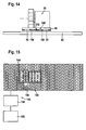
- a sixth embodiment shown in Figs. 14 and 15 are likewise those elements that correspond to those of the first embodiment are identical, provided with the same reference numerals, so that in terms of Description and training thereof to the full extent to the statements to the first embodiment reference is made.
- the holding device works 140 'in the fifth embodiment not with a vacuum pad 142nd but contactless in that the holding device 140 'an electromagnetic Attraction FE generates, which contributes to the hold-down force FN makes, and thus the foot member 46 in the direction of the guide base 42 charged.
- the holding device 140 'an electromagnetic Attraction FE generates, which contributes to the hold-down force FN makes, and thus the foot member 46 in the direction of the guide base 42 charged.
- the primary element 150 in turn comprises pole elements 154, not shown Have windings and pole shoes and by energizing the Windings are magnetizable.
- At least one primary element 150 preferably at least one electrically magnetizable primary element 150 is provided, which with at least a secondary element 152 provided in the foot member 46 interacts.
- the secondary element 152 in turn comprises magnetizable pole elements 156, the permanent magnets or magnetizable short-circuit windings can be according to secondary parts of linear motors.
- a controller 158 is preferably provided, which according to the position of the foot member 46 only those pole elements 154th the primary element 150 drives, over which the foot member 46 with his Secondary element 152 is.
- the controller 158 operates on the basis of information of the Position controller 100 for positioning the processing unit 20 relative to the machine frame 10.
- pole elements 154 of the primary element 150 are similar to a checkerboard pattern arranged so that each pole element 154 in each case in a limited partial area of the base guide surface 44 a magnetic field generated.
- At least one primary element 150 and at least one secondary element 152 are present, which also has a Allow operation as a linear motor, consists in the sixth embodiment also the possibility of the primary element 150 and the secondary element 152 not only to generate the force FE but also at the same time to be used as drive means 160, in which case the position control 100 with the control 158 for the selection of the pole elements 154th cooperates to form the pole elements 154 corresponding to a two-dimensional one To control linear motor, so that the one mechanical drive device 90, as related to the first, second and third Embodiment described for moving the processing unit 20th is not required.
- the tool turret 70 ' is only by represents the turret 74 'which is directly on the foot element 46 sits and is firmly connected to the foot member 46.
- the foot member 46 is the same as in the sixth embodiment by the drive means 160 relative to the guide base 42 movable, the drive means 160 not only exploited to is, the guide member 46 in the direction of movement directions X and Z move linearly, but with appropriate control of the pole elements 154th of the primary element 150 can be used to the guide element 46 about an axis perpendicular to the base guide surface 44 axis 162 turn, which in this case the rotation axis for the fixed to the foot element 46 connected turret 74 ', so that the drive device 160th at the same time capable of the turret 74 'about the axis 162 to rotate and thus different tools 22 in the working position in the same way as with a rotation of the turret 74 conventionally about the turret axis 76 takes place, such as in Described in connection with the first embodiment.
Landscapes
- Engineering & Computer Science (AREA)
- Mechanical Engineering (AREA)
- General Engineering & Computer Science (AREA)
- Machine Tool Units (AREA)
Abstract
Description
- Fig. 1
- eine Seitenansicht eines ersten Ausführungsbeispiels einer erfindungsgemäßen Werkzeugmaschine in Richtung eines Pfeils B in Fig. 2 ohne Antriebseinrichtung;
- Fig. 2
- eine Draufsicht auf das erste Ausführungsbeispiel in Richtung des Pfeils A in Fig. 1;
- Fig. 3
- eine vergrößerte ausschnittsweise Darstellung ähnlich Fig. 1 eines Teilbereichs eines in Fig. 1 dargestellten Fußelements;
- Fig. 4
- eine grafische Darstellung einer vom hydrostatischen Gleitfilm bei der erfindungsgemäßen Lösung erzeugten Abhebekraft in Abhängigkeit von dessen Filmdicke und eine Darstellung von einzelnen Komponenten einer von der Abhebekraft kompensierten Niederhaltekraft;
- Fig. 5
- eine Darstellung des ersten Ausführungsbeispiels ähnlich Fig. 2 mit einer erfindungsgemäßen Antriebseinrichtung;
- Fig. 6
- einen Schnitt längs Linie 6-6 in Fig. 5;
- Fig. 7
- einen Schnitt ähnlich Fig. 6 durch ein zweites Ausführungsbeispiel einer erfindungsgemäßen Werkzeugmaschine;
- Fig. 8
- eine Draufsicht ähnlich Fig. 5 auf eine Antriebseinrichtung eines dritten Ausführungsbeispiels einer erfindungsgemäßen Werkzeugmaschine;
- Fig. 9
- eine Ansicht ähnlich Fig. 1 eines vierten Ausführungsbeispiels der erfindungsgemäßen Werkzeugmaschine;
- Fig. 10
- eine Ansicht ähnlich Fig. 2 des vierten Ausführungsbeispiels der erfindungsgemäßen Werkzeugmaschine;
- Fig. 11
- eine Ansicht ähnlich Fig. 1 eines fünften Ausführungsbeispiels einer erfindungsgemäßen Werkzeugmaschine allerdings ohne Werkstückspindel;
- Fig. 12
- eine Darstellung ähnlich Fig. 2 beim fünften Ausführungsbeispiel der erfindungsgemäßen Werkzeugmaschine;
- Fig. 13
- eine ausschnittsweise vergrößerte Darstellung ähnlich Fig. 3 beim fünften Ausführungsbeispiel der erfindungsgemäßen Werkzeugmaschine;
- Fig. 14
- eine Darstellung ähnlich Fig. 1 eines sechsten Ausführungsbeispiels der erfindungsgemäßen Werkzeugmaschine;
- Fig. 15
- eine Darstellung ähnlich Fig. 2 des sechsten Ausführungsbeispiels der erfindungsgemäßen Werkzeugmaschine und
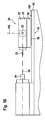
- Fig. 16
- eine Darstellung ähnlich Fig. 1 eines siebten Ausführungsbeispiels der erfindungsgemäßen Werkzeugmaschine.
Claims (36)
- Werkzeugmaschine umfassend ein Maschinengestell (10), eine gegenüber dem Maschinengestell (10) mindestens in einer zweidimensionalen Bewegungsebene (X/Z) bewegbare Bearbeitungseinheit (20) und eine Führungsrichtung (20) zur Führung der Bearbeitungseinheit (20) in der zweidimensionalen Bewegungsebene (X/Z) mit einer eine Basisführungsfläche (44) aufweisenden Führungsbasis (42) und mit einem die Bearbeitungseinheit (20) tragenden Fußelement (46), welches eine der Basisführungsfläche (44) zugewandte Fußführungsfläche (48) aufweist,
dadurch gekennzeichnet, daß zwischen der Fußführungsfläche (48) und der Basisführungsfläche (44) ein hydrostatischer Gleitfilm (50) vorgesehen ist, auf welchem das Fußelement (46) mit seiner Fußführungsfläche (48) relativ zur Führungsbasis gleitet. - Werkzeugmaschine nach Anspruch 1, dadurch gekennzeichnet, daß die Basisführungsfläche (44) in jeder der beiden die Bewegungsebene (X/Z) aufspannenden Bewegungsrichtungen (X/Z) eine Ausdehnung aufweist, die größer ist als die maximale Ausdehnung der Fußführungsfläche (48) in dieser Richtung.
- Werkzeugmaschine nach Anspruch 2, dadurch gekennzeichnet, daß die Ausdehnung der Basisführungsfläche (44) mindestens das 1,5-fache der maximalen Ausdehnung der Fußführungsfläche (48) in der jeweiligen Richtung beträgt.
- Werkzeugmaschine nach einem der voranstehenden Ansprüche, dadurch gekennzeichnet, daß die Basisführungsfläche (44) eine zusammenhängende Fläche ist.
- Werkzeugmaschine nach einem der voranstehenden Ansprüche, dadurch gekennzeichnet, daß die Basisführungsfläche (44) durchbruchsfrei ausgebildet ist.
- Werkzeugmaschine nach einem der voranstehenden Ansprüche, dadurch gekennzeichnet, daß die Basisführungsfläche (44) ausnehmungsfrei zusammenhängend ausgebildet ist.
- Werkzeugmaschine nach einem der voranstehenden Ansprüche, dadurch gekennzeichnet, daß das Fußelement (46) mit mindestens einer Zuführung (52) für ein den hydrostatischen Gleitfilm (50) bildendes Gleitmedium versehen ist.
- Werkzeugmaschine nach Anspruch 7, dadurch gekennzeichnet, daß das Fußelement (46) mit mehreren Zuführungen (52) für das Gleitmedium versehen ist.
- Werkzeugmaschine nach Anspruch 8, dadurch gekennzeichnet, daß das Fußelement (46) mit mindestens drei Zuführungen (52) für das Gleitmedium versehen ist.
- Werkzeugmaschine nach einem der Ansprüche 8 oder 9, dadurch gekennzeichnet, daß die Zuführungen (52) für das Gleitmedium in einem außenliegenden Bereich der Fußführungsfläche (48) angeordnet sind.
- Werkzeugmaschine nach einem der Ansprüche 7 bis 10, dadurch gekennzeichnet, daß der mindestens einen Zuführung (52) für Gleitmedium eine Einstelleinrichtung (60) für eine Einstellung einer Zuflußmenge des Gleitmediums zugeordnet ist.
- Werkzeugmaschine nach einem der voranstehenden Ansprüche, dadurch gekennzeichnet, daß der vom Gleitmedium erzeugte hydrostatische Gleitfilm (50) eine einem unmittelbaren Aufliegen der Fußführungsfläche (48) auf der Basisführungsfläche (44) entgegenwirkende Abhebekraft (FA) erzeugt.
- Werkzeugmaschine nach Anspruch 12, dadurch gekennzeichnet, daß die Abhebekraft (FA) eine auf das Fußelement (46) wirkende Niederhaltekraft (FN) kompensiert, welche zumindest eine senkrecht auf der Basisführungsfläche (44) stehende Komponente der Gewichtskraft (FG) der Bearbeitungseinheit (20) umfaßt.
- Werkzeugmaschine nach Anspruch 12 oder 13, dadurch gekennzeichnet, daß der hydrostatische Gleitfilm (50) sich derart verhält, daß die Abhebekraft (FA) durch zerstörungsfreie Kompression des hydrostatischen Gleitfilms (50) so weit vergrößerbar ist, daß mit der Abhebekraft (FA) sämtliche bei einer Bearbeitung eines Werkstücks (24) auftretenden Niederhaltekräfte (FN) kompensierbar sind.
- Werkzeugmaschine nach Anspruch 14, dadurch gekennzeichnet, daß der hydrostatische Gleitfilm (50) im bearbeitungsfreien Zustand durch eine derart große Niederhaltekraft (FN) beaufschlagt ist, daß der Anstieg der Niederhaltekraft (FN) bei Bearbeitung des Werkstücks (24) zu einer Verringerung der Dicke des hydrostatischen Gleitfilms (50) um ungefähr 50% oder weniger führt.
- Werkzeugmaschine nach einem der voranstehenden Ansprüche, dadurch gekennzeichnet, daß eine das Fußelement (46) und die Führungsbasis (42) mit einer der Abhebekraft (FA) entgegenwirkenden Anziehungskraft (FU, FE) beaufschlagende Halteeinrichtung (140) vorgesehen ist.
- Werkzeugmaschine nach Anspruch 16, dadurch gekennzeichnet, daß die Halteeinrichtung (140) berührungslos zwischen der Führungsbasis (42) und dem Fußelement (46) wirkt.
- Werkzeugmaschine nach Anspruch 17, dadurch gekennzeichnet, daß die Halteeinrichtung (140) zwischen der Führungsbasis (42) und dem Fußelement (46) ein Unterdruckpolster (142) erzeugt.
- Werkzeugmaschine nach Anspruch 18, dadurch gekennzeichnet, daß das Unterdruckpolster (142) durch eine Ausnehmung (144) im Fußelement (46) festgelegt ist.
- Werkzeugmaschine nach Anspruch 19, dadurch gekennzeichnet, daß die Zuführungen (52) für das Gleitmedium um die Ausnehmung (144) herum angeordnet sind.
- Werkzeugmaschine nach einem der Ansprüche 17 bis 20, dadurch gekennzeichnet, daß die Halteeinrichtung (140') die Anziehungskräfte (FE) durch magnetische Anziehung erzeugt.
- Werkzeugmaschine nach Anspruch 21, dadurch gekennzeichnet, daß die Halteeinrichtung (140') mindestens einen Elektromagnet (150) umfaßt.
- Werkzeugmaschine nach Anspruch 22, dadurch gekennzeichnet, daß die Halteeinrichtung (140') mindestens ein Primärteil (150) und mindestens ein Sekundärteil (152) aufweist, von denen eines in der Führungsbasis (42) und das andere in dem Fußelement (46) angeordnet ist.
- Werkzeugmaschine nach Anspruch 23, dadurch gekennzeichnet, daß das mindestens eine Sekundärteil (152) im Fußelement (46) angeordnet ist und das mindestens eine Primärteil (150) in der Führungsbasis (42) angeordnet ist.
- Werkzeugmaschine nach Anspruch 23 oder 24, dadurch gekennzeichnet, daß das Sekundärteil (152) mehrere Polelemente (156) umfaßt.
- Werkzeugmaschine nach einem der Ansprüche 23 bis 25, dadurch gekennzeichnet, daß das Primärteil (150) mehrere Polelemente (154) umfaßt.
- Werkzeugmaschine nach Anspruch 26, dadurch gekennzeichnet, daß die Polelemente (154) einzeln ansteuerbar sind.
- Werkzeugmaschine nach einem der voranstehenden Ansprüche, dadurch gekennzeichnet, daß die Bearbeitungseinheit (20) und das Fußelement (46) durch eine Antriebseinrichtung (90, 160) in der zweidimensionalen Bewegungsebene (X/Z) bewegbar sind.
- Werkzeugmaschine nach Anspruch 28, dadurch gekennzeichnet, daß die Antriebseinrichtung (90) stabkinematische Elemente (92, 94, 96) umfaßt, mit denen die Bearbeitungseinheit (20) in mindestens einer Bewegungsrichtung (X/Z) bewegbar ist.
- Werkzeugmaschine nach Anspruch 29, dadurch gekennzeichnet, daß die Antriebseinrichtung (90) als zweidimensional wirksame stabkinematischer Antrieb (90) ausgebildet ist.
- Werkzeugmaschine nach Anspruch 30, dadurch gekennzeichnet, daß der stabkinematische Antrieb (90) auf einer einem in Arbeitsstellung stehenden Werkzeug (22A) gegenüberliegenden Seite der Bearbeitungseinheit (20) angeordnet ist.
- Werkzeugmaschine nach Anspruch 30 oder 31, dadurch gekennzeichnet, daß der stabkinematische Antrieb (90) gelenkig gelagerte und längenveränderbare Antriebsstreben (92, 94, 96) aufweist.
- Werkzeugmaschine nach Anspruch 30 oder 31, dadurch gekennzeichnet, daß der stabkinematische Antrieb (90') gelenkig gelagerte längeninvariante, jedoch auf einer Linearführung (130) mit Schlitten (126, 128) relativ zueinander bewegbare Antriebsstreben (92', 94', 96') aufweist.
- Werkzeugmaschine nach Anspruch 30 oder 31, dadurch gekennzeichnet, daß die mindestens ein Primärteil (150) und mindestens ein Sekundärteil (152) aufweisende Halteeinrichtung (140') als Linearantrieb der Antriebseinrichtung (160) betreibbar ist.
- Werkzeugmaschine nach Anspruch 30 oder 31, dadurch gekennzeichnet, daß die mindestens ein Primärteil (150) und mindestens ein Sekundärteil (152) aufweisende Halteeinrichtung als zweidimensionale Antriebseinrichtung (160) betreibbar ist.
- Werkzeugmaschine nach Anspruch 35, dadurch gekennzeichnet, daß mit der Antriebseinrichtung (160) die Bearbeitungseinheit (20) um eine senkrecht zur Basisführungsfläche (44) stehende Achse (162) drehbar ist.
Applications Claiming Priority (2)
| Application Number | Priority Date | Filing Date | Title |
|---|---|---|---|
| DE102004004020 | 2004-01-20 | ||
| DE102004004020A DE102004004020A1 (de) | 2004-01-20 | 2004-01-20 | Werkzeugmaschine |
Publications (2)
| Publication Number | Publication Date |
|---|---|
| EP1557237A2 true EP1557237A2 (de) | 2005-07-27 |
| EP1557237A3 EP1557237A3 (de) | 2005-09-14 |
Family
ID=34625804
Family Applications (1)
| Application Number | Title | Priority Date | Filing Date |
|---|---|---|---|
| EP05000976A Ceased EP1557237A3 (de) | 2004-01-20 | 2005-01-19 | Werkzeugmaschine mit einem hydrostatischen Gleitfilm |
Country Status (2)
| Country | Link |
|---|---|
| EP (1) | EP1557237A3 (de) |
| DE (1) | DE102004004020A1 (de) |
Cited By (1)
| Publication number | Priority date | Publication date | Assignee | Title |
|---|---|---|---|---|
| EP1917447A4 (de) * | 2005-08-23 | 2011-11-23 | Korea Mach & Materials Inst | Fördereinrichtung für statische lager mit magnetischer vorspannung und bewegungsfehlerkorrekturfunktionen |
Families Citing this family (1)
| Publication number | Priority date | Publication date | Assignee | Title |
|---|---|---|---|---|
| DE102019005965B4 (de) * | 2019-08-23 | 2026-01-22 | Kern Microtechnik Gmbh | Lineares Antriebs- und Führungslager |
Family Cites Families (9)
| Publication number | Priority date | Publication date | Assignee | Title |
|---|---|---|---|---|
| FR1311765A (fr) * | 1960-05-23 | 1962-12-14 | Derefa Etablissement Pour Le D | Installation de graissage sous pression de glissières d'organes de machines-outils |
| NL276532A (de) * | 1962-03-28 | |||
| CA968019A (en) * | 1971-09-08 | 1975-05-20 | Walter E. Hinds | Positioning system using synchronous motor |
| US4080009A (en) * | 1976-09-29 | 1978-03-21 | Giddings & Lewis, Inc. | Servostatic bearing system with variable stiffness |
| CH633740A5 (fr) * | 1980-01-25 | 1982-12-31 | Charmilles Sa Ateliers | Machine-outil comprenant une table mobile. |
| US4798985A (en) * | 1987-02-17 | 1989-01-17 | Anwar Chitavat | Linear motor with air-lift bearing unloading |
| DE3888102D1 (de) * | 1987-11-25 | 1994-04-07 | Esec Sa | Einrichtung zur Durchführung der Zustellbewegung eines Arbeitsorgans zu einer Arbeitsstation. |
| JP3128709B2 (ja) * | 1992-08-04 | 2001-01-29 | 株式会社新川 | 非接触型移動テーブル |
| DE10019788A1 (de) * | 2000-04-20 | 2001-10-31 | Index Werke Kg Hahn & Tessky | Werkzeugmaschine |
-
2004
- 2004-01-20 DE DE102004004020A patent/DE102004004020A1/de not_active Ceased
-
2005
- 2005-01-19 EP EP05000976A patent/EP1557237A3/de not_active Ceased
Cited By (1)
| Publication number | Priority date | Publication date | Assignee | Title |
|---|---|---|---|---|
| EP1917447A4 (de) * | 2005-08-23 | 2011-11-23 | Korea Mach & Materials Inst | Fördereinrichtung für statische lager mit magnetischer vorspannung und bewegungsfehlerkorrekturfunktionen |
Also Published As
| Publication number | Publication date |
|---|---|
| EP1557237A3 (de) | 2005-09-14 |
| DE102004004020A1 (de) | 2005-08-11 |
Similar Documents
| Publication | Publication Date | Title |
|---|---|---|
| DE4495551C2 (de) | Z-Achsen-Antrieb für eine Werkzeugmaschine | |
| DE602004006807T2 (de) | Bearbeitungsmaschine | |
| EP2301712B1 (de) | Werkstückträger und Werkzeugmaschine | |
| EP2349639B1 (de) | Werkzeugmaschine mit schwimmend gelagerter trägereinrichtung | |
| DE102014118335A1 (de) | Linearantriebseinheit mit Linearmotor und eine Werkzeugmaschine damit | |
| DE3100141A1 (de) | Werkzeugmaschine mit einem beweglichen tisch fuer ein werkstueck | |
| DE112008000864T5 (de) | Spindelantriebsmechanismus für eine Werkzeugmaschine | |
| DE10116994A1 (de) | Werkzeugmaschine | |
| DE68926700T2 (de) | Schneidgerät für nichtkreisförmige Querschnitte | |
| DE69202003T2 (de) | Feinstbearbeitungsmaschine mit pneumatischer Kraftsteuerung des Werkzeuges. | |
| DE102015114727A1 (de) | Werkzeugmaschine mit einer Feinbearbeitungsspindel | |
| EP1189726B1 (de) | Werkzeugmaschine | |
| DE102013216175A1 (de) | Führung und Führungselement | |
| DE4241708C2 (de) | Elektroerodiermaschine | |
| DE10224100B9 (de) | Lagerung eines Rotationsteils | |
| EP1557237A2 (de) | Werkzeugmaschine mit einem hydrostatischen Gleitfilm | |
| DE102019106974A1 (de) | Werkzeugmaschine zum Bearbeiten eines Werkstückes | |
| EP1466684A1 (de) | Maschine zur Bearbeitung von Werkstücken, insbesondere von Kurbel- und Nockenwellen, mit mindestens einem Innen-Rundfräswerkzeug | |
| DE19904253A1 (de) | Werkzeugmaschine | |
| EP2185314B1 (de) | Werkzeugmaschine mit beweglichen werkstückschlitten | |
| DE19826519C2 (de) | Hydrostatische Führung | |
| DE112011103440B4 (de) | Kurbelwellenfräsmaschine | |
| DE3412576C1 (de) | Fraes-Bohrvorrichtung | |
| WO2005032754A1 (de) | Schweisszange | |
| DE60013448T2 (de) | Antriebssystem einer werkzeugmaschine |
Legal Events
| Date | Code | Title | Description |
|---|---|---|---|
| PUAI | Public reference made under article 153(3) epc to a published international application that has entered the european phase |
Free format text: ORIGINAL CODE: 0009012 |
|
| AK | Designated contracting states |
Kind code of ref document: A2 Designated state(s): AT BE BG CH CY CZ DE DK EE ES FI FR GB GR HU IE IS IT LI LT LU MC NL PL PT RO SE SI SK TR |
|
| AX | Request for extension of the european patent |
Extension state: AL BA HR LV MK YU |
|
| PUAL | Search report despatched |
Free format text: ORIGINAL CODE: 0009013 |
|
| AK | Designated contracting states |
Kind code of ref document: A3 Designated state(s): AT BE BG CH CY CZ DE DK EE ES FI FR GB GR HU IE IS IT LI LT LU MC NL PL PT RO SE SI SK TR |
|
| AX | Request for extension of the european patent |
Extension state: AL BA HR LV MK YU |
|
| 17P | Request for examination filed |
Effective date: 20060310 |
|
| AKX | Designation fees paid |
Designated state(s): AT BE BG CH CY CZ DE DK EE ES FI FR GB GR HU IE IS IT LI LT LU MC NL PL PT RO SE SI SK TR |
|
| 17Q | First examination report despatched |
Effective date: 20060727 |
|
| 17Q | First examination report despatched |
Effective date: 20060727 |
|
| STAA | Information on the status of an ep patent application or granted ep patent |
Free format text: STATUS: THE APPLICATION HAS BEEN REFUSED |
|
| 18R | Application refused |
Effective date: 20080707 |