EP1557138B1 - Stent expansible avec dispositif de couplage - Google Patents
Stent expansible avec dispositif de couplage Download PDFInfo
- Publication number
- EP1557138B1 EP1557138B1 EP05001229A EP05001229A EP1557138B1 EP 1557138 B1 EP1557138 B1 EP 1557138B1 EP 05001229 A EP05001229 A EP 05001229A EP 05001229 A EP05001229 A EP 05001229A EP 1557138 B1 EP1557138 B1 EP 1557138B1
- Authority
- EP
- European Patent Office
- Prior art keywords
- stent
- portions
- coupling device
- male
- expansion
- Prior art date
- Legal status (The legal status is an assumption and is not a legal conclusion. Google has not performed a legal analysis and makes no representation as to the accuracy of the status listed.)
- Expired - Fee Related
Links
Images


Classifications
-
- A—HUMAN NECESSITIES
- A61—MEDICAL OR VETERINARY SCIENCE; HYGIENE
- A61F—FILTERS IMPLANTABLE INTO BLOOD VESSELS; PROSTHESES; DEVICES PROVIDING PATENCY TO, OR PREVENTING COLLAPSING OF, TUBULAR STRUCTURES OF THE BODY, e.g. STENTS; ORTHOPAEDIC, NURSING OR CONTRACEPTIVE DEVICES; FOMENTATION; TREATMENT OR PROTECTION OF EYES OR EARS; BANDAGES, DRESSINGS OR ABSORBENT PADS; FIRST-AID KITS
- A61F2/00—Filters implantable into blood vessels; Prostheses, i.e. artificial substitutes or replacements for parts of the body; Appliances for connecting them with the body; Devices providing patency to, or preventing collapsing of, tubular structures of the body, e.g. stents
- A61F2/82—Devices providing patency to, or preventing collapsing of, tubular structures of the body, e.g. stents
- A61F2/86—Stents in a form characterised by the wire-like elements; Stents in the form characterised by a net-like or mesh-like structure
- A61F2/90—Stents in a form characterised by the wire-like elements; Stents in the form characterised by a net-like or mesh-like structure characterised by a net-like or mesh-like structure
- A61F2/91—Stents in a form characterised by the wire-like elements; Stents in the form characterised by a net-like or mesh-like structure characterised by a net-like or mesh-like structure made from perforated sheet material or tubes, e.g. perforated by laser cuts or etched holes
- A61F2/915—Stents in a form characterised by the wire-like elements; Stents in the form characterised by a net-like or mesh-like structure characterised by a net-like or mesh-like structure made from perforated sheet material or tubes, e.g. perforated by laser cuts or etched holes with bands having a meander structure, adjacent bands being connected to each other
-
- A—HUMAN NECESSITIES
- A61—MEDICAL OR VETERINARY SCIENCE; HYGIENE
- A61F—FILTERS IMPLANTABLE INTO BLOOD VESSELS; PROSTHESES; DEVICES PROVIDING PATENCY TO, OR PREVENTING COLLAPSING OF, TUBULAR STRUCTURES OF THE BODY, e.g. STENTS; ORTHOPAEDIC, NURSING OR CONTRACEPTIVE DEVICES; FOMENTATION; TREATMENT OR PROTECTION OF EYES OR EARS; BANDAGES, DRESSINGS OR ABSORBENT PADS; FIRST-AID KITS
- A61F2/00—Filters implantable into blood vessels; Prostheses, i.e. artificial substitutes or replacements for parts of the body; Appliances for connecting them with the body; Devices providing patency to, or preventing collapsing of, tubular structures of the body, e.g. stents
- A61F2/02—Prostheses implantable into the body
- A61F2/24—Heart valves ; Vascular valves, e.g. venous valves; Heart implants, e.g. passive devices for improving the function of the native valve or the heart muscle; Transmyocardial revascularisation [TMR] devices; Valves implantable in the body
- A61F2/2475—Venous valves
-
- A—HUMAN NECESSITIES
- A61—MEDICAL OR VETERINARY SCIENCE; HYGIENE
- A61F—FILTERS IMPLANTABLE INTO BLOOD VESSELS; PROSTHESES; DEVICES PROVIDING PATENCY TO, OR PREVENTING COLLAPSING OF, TUBULAR STRUCTURES OF THE BODY, e.g. STENTS; ORTHOPAEDIC, NURSING OR CONTRACEPTIVE DEVICES; FOMENTATION; TREATMENT OR PROTECTION OF EYES OR EARS; BANDAGES, DRESSINGS OR ABSORBENT PADS; FIRST-AID KITS
- A61F2/00—Filters implantable into blood vessels; Prostheses, i.e. artificial substitutes or replacements for parts of the body; Appliances for connecting them with the body; Devices providing patency to, or preventing collapsing of, tubular structures of the body, e.g. stents
- A61F2/82—Devices providing patency to, or preventing collapsing of, tubular structures of the body, e.g. stents
- A61F2/86—Stents in a form characterised by the wire-like elements; Stents in the form characterised by a net-like or mesh-like structure
- A61F2/90—Stents in a form characterised by the wire-like elements; Stents in the form characterised by a net-like or mesh-like structure characterised by a net-like or mesh-like structure
- A61F2/91—Stents in a form characterised by the wire-like elements; Stents in the form characterised by a net-like or mesh-like structure characterised by a net-like or mesh-like structure made from perforated sheet material or tubes, e.g. perforated by laser cuts or etched holes
- A61F2/915—Stents in a form characterised by the wire-like elements; Stents in the form characterised by a net-like or mesh-like structure characterised by a net-like or mesh-like structure made from perforated sheet material or tubes, e.g. perforated by laser cuts or etched holes with bands having a meander structure, adjacent bands being connected to each other
- A61F2002/91533—Stents in a form characterised by the wire-like elements; Stents in the form characterised by a net-like or mesh-like structure characterised by a net-like or mesh-like structure made from perforated sheet material or tubes, e.g. perforated by laser cuts or etched holes with bands having a meander structure, adjacent bands being connected to each other characterised by the phase between adjacent bands
- A61F2002/91541—Adjacent bands are arranged out of phase
-
- A—HUMAN NECESSITIES
- A61—MEDICAL OR VETERINARY SCIENCE; HYGIENE
- A61F—FILTERS IMPLANTABLE INTO BLOOD VESSELS; PROSTHESES; DEVICES PROVIDING PATENCY TO, OR PREVENTING COLLAPSING OF, TUBULAR STRUCTURES OF THE BODY, e.g. STENTS; ORTHOPAEDIC, NURSING OR CONTRACEPTIVE DEVICES; FOMENTATION; TREATMENT OR PROTECTION OF EYES OR EARS; BANDAGES, DRESSINGS OR ABSORBENT PADS; FIRST-AID KITS
- A61F2/00—Filters implantable into blood vessels; Prostheses, i.e. artificial substitutes or replacements for parts of the body; Appliances for connecting them with the body; Devices providing patency to, or preventing collapsing of, tubular structures of the body, e.g. stents
- A61F2/82—Devices providing patency to, or preventing collapsing of, tubular structures of the body, e.g. stents
- A61F2/86—Stents in a form characterised by the wire-like elements; Stents in the form characterised by a net-like or mesh-like structure
- A61F2/90—Stents in a form characterised by the wire-like elements; Stents in the form characterised by a net-like or mesh-like structure characterised by a net-like or mesh-like structure
- A61F2/91—Stents in a form characterised by the wire-like elements; Stents in the form characterised by a net-like or mesh-like structure characterised by a net-like or mesh-like structure made from perforated sheet material or tubes, e.g. perforated by laser cuts or etched holes
- A61F2/915—Stents in a form characterised by the wire-like elements; Stents in the form characterised by a net-like or mesh-like structure characterised by a net-like or mesh-like structure made from perforated sheet material or tubes, e.g. perforated by laser cuts or etched holes with bands having a meander structure, adjacent bands being connected to each other
- A61F2002/9155—Adjacent bands being connected to each other
- A61F2002/91566—Adjacent bands being connected to each other connected trough to trough
-
- A—HUMAN NECESSITIES
- A61—MEDICAL OR VETERINARY SCIENCE; HYGIENE
- A61F—FILTERS IMPLANTABLE INTO BLOOD VESSELS; PROSTHESES; DEVICES PROVIDING PATENCY TO, OR PREVENTING COLLAPSING OF, TUBULAR STRUCTURES OF THE BODY, e.g. STENTS; ORTHOPAEDIC, NURSING OR CONTRACEPTIVE DEVICES; FOMENTATION; TREATMENT OR PROTECTION OF EYES OR EARS; BANDAGES, DRESSINGS OR ABSORBENT PADS; FIRST-AID KITS
- A61F2/00—Filters implantable into blood vessels; Prostheses, i.e. artificial substitutes or replacements for parts of the body; Appliances for connecting them with the body; Devices providing patency to, or preventing collapsing of, tubular structures of the body, e.g. stents
- A61F2/82—Devices providing patency to, or preventing collapsing of, tubular structures of the body, e.g. stents
- A61F2/86—Stents in a form characterised by the wire-like elements; Stents in the form characterised by a net-like or mesh-like structure
- A61F2/90—Stents in a form characterised by the wire-like elements; Stents in the form characterised by a net-like or mesh-like structure characterised by a net-like or mesh-like structure
- A61F2/91—Stents in a form characterised by the wire-like elements; Stents in the form characterised by a net-like or mesh-like structure characterised by a net-like or mesh-like structure made from perforated sheet material or tubes, e.g. perforated by laser cuts or etched holes
- A61F2/915—Stents in a form characterised by the wire-like elements; Stents in the form characterised by a net-like or mesh-like structure characterised by a net-like or mesh-like structure made from perforated sheet material or tubes, e.g. perforated by laser cuts or etched holes with bands having a meander structure, adjacent bands being connected to each other
- A61F2002/9155—Adjacent bands being connected to each other
- A61F2002/91591—Locking connectors, e.g. using male-female connections
Definitions
- the invention relates to a stent for insertion and / or expansion in a lumen or for implanting in a living body, with at least two sections of a stent structure, which are moved towards each other during expansion of the stent.
- Stents of the above type are used to protect a lumen of a living body, such as blood vessels, esophagus, urethra or kidney ducts, from collapsing or occluding by expanding a substantially tubular wall structure of the stent within the channel.
- the stent used can increase the flow cross-section of the lumen for a medium flowing therein or permanently keep sufficiently large.
- stents are used as carriers of medicaments which make at least local therapy possible in a body passageway.
- stents can be used as aneurysm stent or endoprosthesis for intracular vessel bagging or as an intraluminal stent.
- stents or spreading structures are used as carriers for implants.
- the wall or stent structure of such stents has a plurality of webs, which are connected to each other at web connectors or nodes.
- the webs are made of a flexible material, such as Nitinol or stainless steel, so that the stent has a slightly flexible wall structure as a whole.
- a once inserted and expanded stent In order to ensure the desired flow cross-section of the lumen, it is desirable for a once inserted and expanded stent to retain its shape as permanently as possible and not further expand or compress later. Further, it would be desirable if the stent took on a predefined shape and then retained it.
- US2002 / 111671 A1 discloses a locking stent having a lockable stent cell having first and second locking members. In the locking position in the expanded state of the stent, a supporting strength due to the locked stent cell is increased.
- US2003 / 0199969 A1 discloses an expandable stent with radial sliding and locking elements that allow expansion of the stent while preventing collapse of an expanded stent.
- the object of the invention is to provide a stent in which unwanted deformations can be reliably prevented.
- the object is according to the invention by a stent.
- a coupling is provided between two sections of the stent or the spreading or support structure, which move relative to one another during an expansion of the stent or the spreading or support structure, which fixes the sections in their staggered position relative to one another and in this way no longer allows undefined further expansion and / or compression of the stent.
- the sections of the stent to be moved assume a predetermined position relative to one another, so that the stent as a whole is likewise brought into a predefined shape with its multiplicity of sections during expansion and also remains in this form.
- the coupling device is designed with a male and a female plug element, of which in particular one is attached to a first of the two sections and the other to the second section substantially stationary.
- the plug-in elements form a non-positive and / or positive connection by means of which the sections are fixed relative to one another in the compressed state of the stent. Further expansion or compression would deform the provided plug-in elements.
- the plug-in elements are therefore designed so stiff that a certain residual flexibility of the stent is maintained in the expanded state, but that nevertheless the desired dimensional accuracy is achieved in this expanded state.
- the coupling device is formed with two web halves, which are aligned substantially coaxially and have opposite end portions, on which at a first end portion of the male and at the second end portion of the female plug element is formed.
- the web halves can be cut out of a single web in the production of the stent according to the invention and thereby also the male and the female plug element can be formed on them.
- the single coupling device is designed with a guide element with which the male plug element is guided into the female plug element when the two sections move towards each other become.
- the coupling device is further formed with two web halves, which are aligned substantially coaxially and at opposite end regions as a guide element for a guide rod and on the other hand have a guide groove.
- the guide rod and the guide groove can be cut particularly cost-effectively during the production of support webs of the stent structure from the material of the stent (for example a shape memory material, in particular nitinol), for example by a laser welding process.
- the axis of the two web halves can advantageously extend substantially parallel to the longitudinal axis of the stent, because in this way it can advantageously be ensured that during the expansion of the stent, the guide rod is almost not bent, but only offset together with the guide groove in parallel. The guide rod therefore also does not pass out of the guide groove radially.
- the two sections are already guided relative to each other with the guide element in the unexpanded state of the stent.
- the coupling device may be designed with at least one hook element or tongue / groove element, for example, latched to an associated female plug element when the two sections are moved towards each other.
- both the stent structure and the therein provided coupling devices can be cut out of the material of the stent in only one operation, are preferably provided as a single structural element of the stent structure at least four webs which are pivotally connected to nodes or bendable and in the expanded state of the stent a closed (essentially polygonal) Ring form, in particular form a diamond shape, in the interior of the coupling device is arranged.
- the coupling device may be formed in this embodiment by means of two web halves, which form a diagonal substantially within the ring shape.
- the coupling device may further be formed with two opposing web halves which are each articulated individually together with two adjacent support webs at a node of the stent structure.
- a heart valve carrier having such a stent.
- a venous valve carrier a vena cava filter, a prostatic sphincter body, and / or an antireflux stent having such a stent.
- a total of substantially circular cylindrical stent or spreading or support structure 10 for insertion or insertion and / or expanding or supporting or carrying in a lumen the stent structure is composed of a plurality of support webs 12.
- the support webs 12 each terminate at nodes 14, which serve as connecting portions for the support webs 12.
- the support webs 12 extend in the compressed state of the stent 10 substantially in the direction of a longitudinal axis 16 of the stent 10 and thereby form a kind of flattened rhombus in which two coaxially arranged web halves 18 and 20 are arranged inside.
- the web halves 18 and 20 are hinged at their ends facing away from each other at one of the nodes 14 and point to their mutually facing end portions on a male or a female plug element 22 and 24.
- the male or female plug element 22 or 24 formed plug or snap connection is merged and locked in this position.
- the latching is done by means of one or more detents 26 which are provided on the male plug element and which engage in each case on a corresponding recess 28 of the female plug element 24.
- the locking lugs 26 can be inserted into the female plug element 24, this is designed by means of two spring arms 30 in which the recesses 28 are formed.
- the locking lug (s) 26 is or are preferably hook-shaped or double-hooked or arrow-shaped, while the corresponding recess (s) 28 have a substantially complementary shape.
- the final step of heat treating such a stent should bridge the difference from stent placement to snapping its snap connections.
- austenite finish (Af) temperature of the stent material may be adjusted to allow manipulation of the stent 10 at normal ambient temperature, ie, at a temperature of about 20 ° C to 25 ° C.
- Externally controlled expanding stents 10 are expanded manually or separately only when the stent is used. In such stents 10 must be ensured that the spring arms 30 at the snap connections in Do not expand permanently or plastically deformed.
- a guide rod 32 is further formed in the foremost region, which is already performed in the compressed state of the stent 10 in a guide groove 34 of the female plug element 24 and further displaced therein.
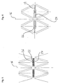
- FIGS. 5 and 6 a second coupling device is shown in which the plug-in elements 22, 24 are provided in the circumferential direction of the stent 10, ie substantially perpendicular to the longitudinal axis 16 of the stent 10.
- the plug-in elements 22, 24 are moved away from each other in the expansion of the stent 10, as in Fig. 6 is shown.
- the plug elements 22, 24 are in this stent 10 in the compressed state of the stent 10 in the approximate position, as in Fig. 5 is shown and move away from each other when the stent 10 is expanded, as in FIG Fig. 6 is shown.
- the detent (s) 26 of the male connector element 22 and the recess (s) 28 of the female plug element 24 are formed so that a latching takes place in the mutually moved away state. It can be formed in the formation of multiple locking lugs 26 and / or recesses 28 a multi-stage latching.
- plug elements 22, 24 are used in combination both in the circumferential direction and in the axial direction.
- different shapes of an expanded stent 10 can be formed by different configuration of the plug elements of a circular shape, as in Fig. 7 is shown.
- stent 10 has three constrictions on its circumference in the expanded state, which are formed by forming different plug-in elements 22, 24.
- other shapes of the expanded stent 10 may be formed by different male members 22, 24, such as an ellipse shape, a cone shape, a waveform, etc.
- the preparation of the stent according to the invention or a preferred Embodiment hereof can take place both from raw material and from flat material, wherein in the latter the stent is later rolled, welded and / or finished.
- the production of the stent can be carried out by means of laser cutting, laser ablation, photochemical etching and / or erosion.
- the production of the stent may also be such that the stent structure is made in an at least partially expanded form and the stent is then reduced to a compressed shape for insertion into the catheter, for example, before it is subsequently at least partially expanded again in the body.
- the invention is particularly useful with balloon expanded stents made of stainless steel, tantalum, niobium, cobalt alloys and other materials such as e.g. Polymers, self-degradable materials (e.g., lactic acid materials or derivatives); and stents of nitinol (nickel-titanium alloys) and / or other self-expanding materials.
- materials such as e.g. Polymers, self-degradable materials (e.g., lactic acid materials or derivatives); and stents of nitinol (nickel-titanium alloys) and / or other self-expanding materials.
- the stent or spreading or support structure according to the invention is particularly preferably used for stabilizing vessels, in particular blood vessels or as a tracheal stent, bronchial stent, transhepatic portosystemic shunt, transhepatic intravenous portosystemic shunt (TIPS), bile duct stent and / or protective device Embolisms (English: Embolic Protective Device).
- the stent or spreading or support structure according to the invention is preferably used as a carrier stent for implants, in particular for a heart valve, a venous valve, a vena cava filter, a prostatic sphincter body and / or as an antireflux stent (gastric valve).
Claims (10)
- Stent (10) destiné à être introduit et/ou expansé dans une lumière, avec au moins deux tronçons (14) d'une structure de stent qui peuvent être déplacés l'un vers l'autre lors de l'expansion du stent (10),
au moins un dispositif de couplage (36) étant disposé entre les deux tronçons (14), au moyen duquel, après au moins un mouvement (X) prédéfini des deux tronçons (14), ces tronçons (14) sont couplés l'un à l'autre,
un éloignement des deux tronçons (14) l'un de l'autre étant empêché par le dispositif de couplage (36) quand le dispositif de couplage (36), après le mouvement (X) prédéfini des deux tronçons (14), couple ces tronçons (14) l'un à l'autre de sorte que la forme globale expansée du stent (10) est fixée de sorte qu'elle ne peut plus être modifiée,
le dispositif de couplage (36) étant formé avec deux moitiés d'entretoise (18 ; 20) qui sont orientées de façon coaxiale et qui présentent, au niveau de zones d'extrémité se faisant face l'une l'autre, un élément de connexion mâle (22) et un élément de connexion femelle (24), un ou plusieurs becs d'encliquetage (26) étant prévus sur l'élément de connexion mâle (22), et un ou plusieurs évidements (28) correspondants étant prévus sur l'élément de connexion femelle (24), caractérisé en ce que, sur l'élément de connexion mâle (22), il est constitué dans la zone la plus en avant une tige de guidage (32), la tige de guidage (32) étant, déjà dans l'état comprimé du stent (10), guidée dans une rainure de guidage (34) de l'élément de connexion femelle (24) et pouvant y être déplacée davantage intérieurement. - Stent (10) selon la revendication 1, en outre avec au moins deux tronçons d'une structure de stent qui, lors de l'expansion du stent (10), sont éloignés l'un de l'autre, au moins un deuxième dispositif de couplage étant disposé entre les deux tronçons, dispositif de couplage au moyen duquel, après un mouvement (X) prédéfini des deux tronçons, ces tronçons sont couplés l'un à l'autre de sorte qu'un déplacement des deux tronçons l'un vers l'autre est empêché.
- Stent selon la revendication 1 ou 2, un élément de connexion parmi l'élément de connexion mâle (22) et l'élément de connexion femelle (24) étant mis en place de façon fixe sur un premier des deux tronçons (14), et l'autre élément de connexion étant mis en place de façon fixe sur le deuxième tronçon (14).
- Stent selon une des revendications précédentes, au moins quatre entretoises d'appui (12) étant prévues qui sont raccordées les unes aux autres en pivotement au niveau de noeuds (14) et forment, dans l'état expansé du stent (10), une forme d'anneau fermée à l'intérieur de laquelle est disposé le dispositif de couplage (36).
- Stent selon la revendication 4, la forme d'anneau fermée formant une forme de losange.
- Stent selon une des revendications précédentes, chaque moitié d'entretoise (18 ; 20) étant articulée au niveau de deux entretoises d'appui (12) voisines au niveau d'un noeud (14) de la structure de stent.
- Stent selon une des revendications précédentes, le dispositif de couplage (36) s'étendant essentiellement en direction d'un axe longitudinal (16) du stent (10).
- Stent selon une des revendications 2 à 6, le deuxième dispositif de couplage s'étendant essentiellement dans la direction circonférentielle du stent (10).
- Support pour une valvule cardiaque avec au moins un stent selon une des revendications précédentes.
- Support pour une valvule veineuse, filtre de veine cave, corps de sphincter prostatique et/ou stent anti-reflux avec au moins un stent selon une des revendications précédentes.
Priority Applications (1)
| Application Number | Priority Date | Filing Date | Title |
|---|---|---|---|
| EP05001229A EP1557138B1 (fr) | 2004-01-21 | 2005-01-21 | Stent expansible avec dispositif de couplage |
Applications Claiming Priority (5)
| Application Number | Priority Date | Filing Date | Title |
|---|---|---|---|
| DE102004003093 | 2004-01-21 | ||
| DE102004003093A DE102004003093B4 (de) | 2004-01-21 | 2004-01-21 | Stent zum Einsetzen und Expandieren in einem Lumen |
| EP04026619 | 2004-11-09 | ||
| EP04026619 | 2004-11-09 | ||
| EP05001229A EP1557138B1 (fr) | 2004-01-21 | 2005-01-21 | Stent expansible avec dispositif de couplage |
Publications (2)
| Publication Number | Publication Date |
|---|---|
| EP1557138A1 EP1557138A1 (fr) | 2005-07-27 |
| EP1557138B1 true EP1557138B1 (fr) | 2012-12-05 |
Family
ID=34636837
Family Applications (1)
| Application Number | Title | Priority Date | Filing Date |
|---|---|---|---|
| EP05001229A Expired - Fee Related EP1557138B1 (fr) | 2004-01-21 | 2005-01-21 | Stent expansible avec dispositif de couplage |
Country Status (1)
| Country | Link |
|---|---|
| EP (1) | EP1557138B1 (fr) |
Cited By (14)
| Publication number | Priority date | Publication date | Assignee | Title |
|---|---|---|---|---|
| US8828079B2 (en) | 2007-07-26 | 2014-09-09 | Boston Scientific Scimed, Inc. | Circulatory valve, system and method |
| US10856984B2 (en) | 2017-08-25 | 2020-12-08 | Neovasc Tiara Inc. | Sequentially deployed transcatheter mitral valve prosthesis |
| US10940001B2 (en) | 2012-05-30 | 2021-03-09 | Neovasc Tiara Inc. | Methods and apparatus for loading a prosthesis onto a delivery system |
| US11311376B2 (en) | 2019-06-20 | 2022-04-26 | Neovase Tiara Inc. | Low profile prosthetic mitral valve |
| US11357622B2 (en) | 2016-01-29 | 2022-06-14 | Neovase Tiara Inc. | Prosthetic valve for avoiding obstruction of outflow |
| US11389291B2 (en) | 2013-04-04 | 2022-07-19 | Neovase Tiara Inc. | Methods and apparatus for delivering a prosthetic valve to a beating heart |
| US11413139B2 (en) | 2011-11-23 | 2022-08-16 | Neovasc Tiara Inc. | Sequentially deployed transcatheter mitral valve prosthesis |
| US11419720B2 (en) | 2010-05-05 | 2022-08-23 | Neovasc Tiara Inc. | Transcatheter mitral valve prosthesis |
| US11464631B2 (en) | 2016-11-21 | 2022-10-11 | Neovasc Tiara Inc. | Methods and systems for rapid retraction of a transcatheter heart valve delivery system |
| US11491006B2 (en) | 2019-04-10 | 2022-11-08 | Neovasc Tiara Inc. | Prosthetic valve with natural blood flow |
| US11497602B2 (en) | 2012-02-14 | 2022-11-15 | Neovasc Tiara Inc. | Methods and apparatus for engaging a valve prosthesis with tissue |
| US11602429B2 (en) | 2019-04-01 | 2023-03-14 | Neovasc Tiara Inc. | Controllably deployable prosthetic valve |
| US11737872B2 (en) | 2018-11-08 | 2023-08-29 | Neovasc Tiara Inc. | Ventricular deployment of a transcatheter mitral valve prosthesis |
| US11779742B2 (en) | 2019-05-20 | 2023-10-10 | Neovasc Tiara Inc. | Introducer with hemostasis mechanism |
Families Citing this family (8)
| Publication number | Priority date | Publication date | Assignee | Title |
|---|---|---|---|---|
| WO2008016578A2 (fr) | 2006-07-31 | 2008-02-07 | Cartledge Richard G | Implants endovasculaires scellables et leurs procédés d'utilisation |
| US9585743B2 (en) | 2006-07-31 | 2017-03-07 | Edwards Lifesciences Cardiaq Llc | Surgical implant devices and methods for their manufacture and use |
| US9408607B2 (en) | 2009-07-02 | 2016-08-09 | Edwards Lifesciences Cardiaq Llc | Surgical implant devices and methods for their manufacture and use |
| US9566178B2 (en) | 2010-06-24 | 2017-02-14 | Edwards Lifesciences Cardiaq Llc | Actively controllable stent, stent graft, heart valve and method of controlling same |
| EP2438872B1 (fr) * | 2010-10-08 | 2020-11-04 | Biotronik AG | Implant médical, notamment stent, pour l'implantation dans un corps animal et/ou humain |
| US9827093B2 (en) | 2011-10-21 | 2017-11-28 | Edwards Lifesciences Cardiaq Llc | Actively controllable stent, stent graft, heart valve and method of controlling same |
| CA2865013C (fr) | 2012-02-22 | 2020-12-15 | Syntheon Cardiology, Llc | Endoprothese a commande active, greffe d'endoprothese, valve cardiaque et methode de commande de celles-ci |
| AU2019290674B2 (en) * | 2018-06-20 | 2022-08-18 | W. L. Gore & Associates, Inc. | Support structure for an implantable device with enhanced compressive stiffness region(s) |
Citations (3)
| Publication number | Priority date | Publication date | Assignee | Title |
|---|---|---|---|---|
| US5019102A (en) * | 1987-12-10 | 1991-05-28 | Eberhard Hoene | Anti-refluxive internal ureteral stent with a dynamic hood-valve at the vesical end for prevention of urinary reflux into the upper urinary tract upon increase of vesical pressure |
| DE19728337A1 (de) * | 1997-07-03 | 1999-01-07 | Inst Mikrotechnik Mainz Gmbh | Implantierbare Gefäßstütze |
| US6245102B1 (en) * | 1997-05-07 | 2001-06-12 | Iowa-India Investments Company Ltd. | Stent, stent graft and stent valve |
Family Cites Families (3)
| Publication number | Priority date | Publication date | Assignee | Title |
|---|---|---|---|---|
| US6623521B2 (en) | 1998-02-17 | 2003-09-23 | Md3, Inc. | Expandable stent with sliding and locking radial elements |
| US6540777B2 (en) | 2001-02-15 | 2003-04-01 | Scimed Life Systems, Inc. | Locking stent |
| DE202004000896U1 (de) * | 2004-01-21 | 2004-03-18 | Admedes Schuessler Gmbh | Stent |
-
2005
- 2005-01-21 EP EP05001229A patent/EP1557138B1/fr not_active Expired - Fee Related
Patent Citations (3)
| Publication number | Priority date | Publication date | Assignee | Title |
|---|---|---|---|---|
| US5019102A (en) * | 1987-12-10 | 1991-05-28 | Eberhard Hoene | Anti-refluxive internal ureteral stent with a dynamic hood-valve at the vesical end for prevention of urinary reflux into the upper urinary tract upon increase of vesical pressure |
| US6245102B1 (en) * | 1997-05-07 | 2001-06-12 | Iowa-India Investments Company Ltd. | Stent, stent graft and stent valve |
| DE19728337A1 (de) * | 1997-07-03 | 1999-01-07 | Inst Mikrotechnik Mainz Gmbh | Implantierbare Gefäßstütze |
Cited By (18)
| Publication number | Priority date | Publication date | Assignee | Title |
|---|---|---|---|---|
| US8828079B2 (en) | 2007-07-26 | 2014-09-09 | Boston Scientific Scimed, Inc. | Circulatory valve, system and method |
| US11419720B2 (en) | 2010-05-05 | 2022-08-23 | Neovasc Tiara Inc. | Transcatheter mitral valve prosthesis |
| US11413139B2 (en) | 2011-11-23 | 2022-08-16 | Neovasc Tiara Inc. | Sequentially deployed transcatheter mitral valve prosthesis |
| US11497602B2 (en) | 2012-02-14 | 2022-11-15 | Neovasc Tiara Inc. | Methods and apparatus for engaging a valve prosthesis with tissue |
| US11617650B2 (en) | 2012-05-30 | 2023-04-04 | Neovasc Tiara Inc. | Methods and apparatus for loading a prosthesis onto a delivery system |
| US10940001B2 (en) | 2012-05-30 | 2021-03-09 | Neovasc Tiara Inc. | Methods and apparatus for loading a prosthesis onto a delivery system |
| US11389294B2 (en) | 2012-05-30 | 2022-07-19 | Neovasc Tiara Inc. | Methods and apparatus for loading a prosthesis onto a delivery system |
| US11389291B2 (en) | 2013-04-04 | 2022-07-19 | Neovase Tiara Inc. | Methods and apparatus for delivering a prosthetic valve to a beating heart |
| US11357622B2 (en) | 2016-01-29 | 2022-06-14 | Neovase Tiara Inc. | Prosthetic valve for avoiding obstruction of outflow |
| US11464631B2 (en) | 2016-11-21 | 2022-10-11 | Neovasc Tiara Inc. | Methods and systems for rapid retraction of a transcatheter heart valve delivery system |
| US10856984B2 (en) | 2017-08-25 | 2020-12-08 | Neovasc Tiara Inc. | Sequentially deployed transcatheter mitral valve prosthesis |
| US11793640B2 (en) | 2017-08-25 | 2023-10-24 | Neovasc Tiara Inc. | Sequentially deployed transcatheter mitral valve prosthesis |
| US11737872B2 (en) | 2018-11-08 | 2023-08-29 | Neovasc Tiara Inc. | Ventricular deployment of a transcatheter mitral valve prosthesis |
| US11602429B2 (en) | 2019-04-01 | 2023-03-14 | Neovasc Tiara Inc. | Controllably deployable prosthetic valve |
| US11491006B2 (en) | 2019-04-10 | 2022-11-08 | Neovasc Tiara Inc. | Prosthetic valve with natural blood flow |
| US11779742B2 (en) | 2019-05-20 | 2023-10-10 | Neovasc Tiara Inc. | Introducer with hemostasis mechanism |
| US11311376B2 (en) | 2019-06-20 | 2022-04-26 | Neovase Tiara Inc. | Low profile prosthetic mitral valve |
| US11931254B2 (en) | 2019-06-20 | 2024-03-19 | Neovasc Tiara Inc. | Low profile prosthetic mitral valve |
Also Published As
| Publication number | Publication date |
|---|---|
| EP1557138A1 (fr) | 2005-07-27 |
Similar Documents
| Publication | Publication Date | Title |
|---|---|---|
| EP1557138B1 (fr) | Stent expansible avec dispositif de couplage | |
| DE102004003093B4 (de) | Stent zum Einsetzen und Expandieren in einem Lumen | |
| DE102009060228B4 (de) | Medizinische Vorrichtungen | |
| DE60206694T2 (de) | Ballonbetätigter Stent mit verriegelbaren Elementen | |
| DE69928915T2 (de) | Expandierbare einheitszelle und intraluminaler stent | |
| DE60121947T2 (de) | Intraluminaler stent | |
| DE602004012037T2 (de) | Abdeckvorrichtung für einen Aneurysemhals | |
| DE69829494T2 (de) | Nachgiebige intraluminale stents | |
| DE69828220T2 (de) | Expandierbare intraluminale Endoprothese | |
| EP0536610B1 (fr) | Dispositif pour la dilatation d'une sténose | |
| DE102008010507B3 (de) | Stent und Verfahren zum Herstellen eines derartigen Stents | |
| EP0734698B9 (fr) | Stent pour implantation transluminale dans des organes creux | |
| DE69533289T2 (de) | Anordnungsverfahren von einem umhüllten, endoluminalen stent | |
| EP3217927B1 (fr) | Stent prothétique | |
| DE60211999T2 (de) | Flexibler Stent | |
| DE10109508A1 (de) | In Längsrichtung flexibler Stent | |
| EP0481365A1 (fr) | Dispositif pour dilater une sténose dans un conduit corporel | |
| CH693441A5 (de) | Ein flexibler ausdehnbarer Stent. | |
| EP3213714A1 (fr) | Catheter de largage et systeme de catheter | |
| EP2799036A1 (fr) | Endoprthèse intraluminale et son procédé de fabrication | |
| EP1555959B1 (fr) | Endoprothese a implanter dans ou autour d'un organe creux | |
| EP1844740B1 (fr) | Stent auto-extensible doté d'une structure à ressort | |
| DE69924260T2 (de) | Expandierbarer stent für kleinlumige gefässe | |
| DE202004000896U1 (de) | Stent | |
| EP1491161B1 (fr) | Arbre flexible |
Legal Events
| Date | Code | Title | Description |
|---|---|---|---|
| PUAI | Public reference made under article 153(3) epc to a published international application that has entered the european phase |
Free format text: ORIGINAL CODE: 0009012 |
|
| AK | Designated contracting states |
Kind code of ref document: A1 Designated state(s): AT BE BG CH CY CZ DE DK EE ES FI FR GB GR HU IE IS IT LI LT LU MC NL PL PT RO SE SI SK TR |
|
| AX | Request for extension of the european patent |
Extension state: AL BA HR LV MK YU |
|
| 17P | Request for examination filed |
Effective date: 20050908 |
|
| AKX | Designation fees paid |
Designated state(s): DE FR GB |
|
| 17Q | First examination report despatched |
Effective date: 20070327 |
|
| REG | Reference to a national code |
Ref country code: DE Ref legal event code: R079 Ref document number: 502005013309 Country of ref document: DE Free format text: PREVIOUS MAIN CLASS: A61F0002060000 Ipc: A61F0002900000 |
|
| GRAP | Despatch of communication of intention to grant a patent |
Free format text: ORIGINAL CODE: EPIDOSNIGR1 |
|
| RIC1 | Information provided on ipc code assigned before grant |
Ipc: A61F 2/90 20060101AFI20120621BHEP |
|
| GRAS | Grant fee paid |
Free format text: ORIGINAL CODE: EPIDOSNIGR3 |
|
| GRAA | (expected) grant |
Free format text: ORIGINAL CODE: 0009210 |
|
| AK | Designated contracting states |
Kind code of ref document: B1 Designated state(s): DE FR GB |
|
| REG | Reference to a national code |
Ref country code: GB Ref legal event code: FG4D Free format text: NOT ENGLISH |
|
| REG | Reference to a national code |
Ref country code: DE Ref legal event code: R096 Ref document number: 502005013309 Country of ref document: DE Effective date: 20130131 |
|
| PLBE | No opposition filed within time limit |
Free format text: ORIGINAL CODE: 0009261 |
|
| STAA | Information on the status of an ep patent application or granted ep patent |
Free format text: STATUS: NO OPPOSITION FILED WITHIN TIME LIMIT |
|
| 26N | No opposition filed |
Effective date: 20130906 |
|
| REG | Reference to a national code |
Ref country code: DE Ref legal event code: R097 Ref document number: 502005013309 Country of ref document: DE Effective date: 20130906 |
|
| PGFP | Annual fee paid to national office [announced via postgrant information from national office to epo] |
Ref country code: GB Payment date: 20141104 Year of fee payment: 11 Ref country code: FR Payment date: 20141028 Year of fee payment: 11 |
|
| PGFP | Annual fee paid to national office [announced via postgrant information from national office to epo] |
Ref country code: DE Payment date: 20160126 Year of fee payment: 12 |
|
| GBPC | Gb: european patent ceased through non-payment of renewal fee |
Effective date: 20160121 |
|
| REG | Reference to a national code |
Ref country code: FR Ref legal event code: ST Effective date: 20160930 |
|
| PG25 | Lapsed in a contracting state [announced via postgrant information from national office to epo] |
Ref country code: GB Free format text: LAPSE BECAUSE OF NON-PAYMENT OF DUE FEES Effective date: 20160121 |
|
| PG25 | Lapsed in a contracting state [announced via postgrant information from national office to epo] |
Ref country code: FR Free format text: LAPSE BECAUSE OF NON-PAYMENT OF DUE FEES Effective date: 20160201 |
|
| REG | Reference to a national code |
Ref country code: DE Ref legal event code: R119 Ref document number: 502005013309 Country of ref document: DE |
|
| PG25 | Lapsed in a contracting state [announced via postgrant information from national office to epo] |
Ref country code: DE Free format text: LAPSE BECAUSE OF NON-PAYMENT OF DUE FEES Effective date: 20170801 |