EP1556680B1 - Method and apparatus for receiving a removable media member - Google Patents
Method and apparatus for receiving a removable media member Download PDFInfo
- Publication number
- EP1556680B1 EP1556680B1 EP03793098.9A EP03793098A EP1556680B1 EP 1556680 B1 EP1556680 B1 EP 1556680B1 EP 03793098 A EP03793098 A EP 03793098A EP 1556680 B1 EP1556680 B1 EP 1556680B1
- Authority
- EP
- European Patent Office
- Prior art keywords
- removable media
- leg
- cleat
- removable
- receiving
- Prior art date
- Legal status (The legal status is an assumption and is not a legal conclusion. Google has not performed a legal analysis and makes no representation as to the accuracy of the status listed.)
- Expired - Lifetime
Links
- 238000000034 method Methods 0.000 title claims description 5
- 239000012530 fluid Substances 0.000 description 37
- 239000000523 sample Substances 0.000 description 27
- 230000003287 optical effect Effects 0.000 description 26
- 210000004369 blood Anatomy 0.000 description 18
- 239000008280 blood Substances 0.000 description 18
- 239000000872 buffer Substances 0.000 description 6
- 230000000994 depressogenic effect Effects 0.000 description 5
- 238000010586 diagram Methods 0.000 description 4
- 210000000265 leukocyte Anatomy 0.000 description 4
- 230000015572 biosynthetic process Effects 0.000 description 3
- 210000004027 cell Anatomy 0.000 description 3
- 238000004891 communication Methods 0.000 description 3
- 238000010790 dilution Methods 0.000 description 3
- 239000012895 dilution Substances 0.000 description 3
- 238000009652 hydrodynamic focusing Methods 0.000 description 3
- 230000002934 lysing effect Effects 0.000 description 3
- 229920000642 polymer Polymers 0.000 description 3
- 230000009471 action Effects 0.000 description 2
- 238000003491 array Methods 0.000 description 2
- 239000010796 biological waste Substances 0.000 description 2
- 238000010276 construction Methods 0.000 description 2
- 230000008878 coupling Effects 0.000 description 2
- 238000010168 coupling process Methods 0.000 description 2
- 238000005859 coupling reaction Methods 0.000 description 2
- 238000013500 data storage Methods 0.000 description 2
- 239000007788 liquid Substances 0.000 description 2
- 230000007246 mechanism Effects 0.000 description 2
- 238000012545 processing Methods 0.000 description 2
- 238000012360 testing method Methods 0.000 description 2
- 239000002699 waste material Substances 0.000 description 2
- 230000003466 anti-cipated effect Effects 0.000 description 1
- 238000000149 argon plasma sintering Methods 0.000 description 1
- 238000005520 cutting process Methods 0.000 description 1
- 238000004163 cytometry Methods 0.000 description 1
- 238000001514 detection method Methods 0.000 description 1
- 230000004069 differentiation Effects 0.000 description 1
- 201000010099 disease Diseases 0.000 description 1
- 208000037265 diseases, disorders, signs and symptoms Diseases 0.000 description 1
- 238000000684 flow cytometry Methods 0.000 description 1
- 230000006870 function Effects 0.000 description 1
- 238000003780 insertion Methods 0.000 description 1
- 230000037431 insertion Effects 0.000 description 1
- 238000010030 laminating Methods 0.000 description 1
- 238000004519 manufacturing process Methods 0.000 description 1
- 238000005259 measurement Methods 0.000 description 1
- 230000008569 process Effects 0.000 description 1
Images


Classifications
-
- G—PHYSICS
- G01—MEASURING; TESTING
- G01N—INVESTIGATING OR ANALYSING MATERIALS BY DETERMINING THEIR CHEMICAL OR PHYSICAL PROPERTIES
- G01N15/00—Investigating characteristics of particles; Investigating permeability, pore-volume or surface-area of porous materials
- G01N15/10—Investigating individual particles
- G01N15/14—Optical investigation techniques, e.g. flow cytometry
- G01N15/1456—Optical investigation techniques, e.g. flow cytometry without spatial resolution of the texture or inner structure of the particle, e.g. processing of pulse signals
- G01N15/1459—Optical investigation techniques, e.g. flow cytometry without spatial resolution of the texture or inner structure of the particle, e.g. processing of pulse signals the analysis being performed on a sample stream
-
- G—PHYSICS
- G01—MEASURING; TESTING
- G01N—INVESTIGATING OR ANALYSING MATERIALS BY DETERMINING THEIR CHEMICAL OR PHYSICAL PROPERTIES
- G01N15/00—Investigating characteristics of particles; Investigating permeability, pore-volume or surface-area of porous materials
- G01N15/10—Investigating individual particles
- G01N15/14—Optical investigation techniques, e.g. flow cytometry
- G01N2015/1486—Counting the particles
Definitions
- the present invention generally relates to removable media, and more particularly, to methods and apparatus for receiving a removable media member.
- removable media members include, for example, removable or replaceable filters, removable ink and toner cartridges, removable data storage devices such as magnetic or optical disks, removable magnetic tape cartridges, removable memory sticks, etc.
- a limitation of many of the existing systems is that the alignment tolerance between the inserted removable media member and the receiving device is often not very precise.
- the receiving device simply includes a slot for receiving the removable media member.
- a more complex mechanical mechanism is provided, such as the mechanical mechanism used in a conventional Video Cassette Recorder (VCR) for receiving VCR tapes.
- VCR Video Cassette Recorder
- two L-shaped cleats are provided for providing two spaced channels for receiving opposing sides of the removable media member. That is, the channel or slot of the first L-shaped cleat and the channel or slot of the second L-shaped cleat may be arranged so that the removable media member slides into both channels when it is inserted between the first member and the second member.
- the second member may include one or more alignment pins that extend toward the first member.
- the removable media member may then include one or more receiving holes for receiving the one or more alignment pins.
- the alignment pins and receiving holes may provide improved alignment between the removable media member and the first and/or second members when the removable media member is secured between the first member and the second member.
- the one or more L-shaped cleats may be used to pull the removable media member away from the second member, thereby separating the one or more receiving holes of the removable media member from the one or more alignment pins that are extending from the second member. With the one or more receiving holes separated from the alignment pins, the removable media member then may be more easily removed from between the first member and the second member.
- a portable flow cytometer system is described in detail below.
- the present invention has wide applicability to numerous other removable media systems including, for example, removable or replaceable filters, removable ink and toner cartridges, removable data storage devices such as magnetic or optical disks, removable magnetic tape cartridges, removable memory sticks, as well as many other systems and/or devices that use removable media.
- FIG. 1 is a perspective view of an illustrative portable cytometer.
- the portable cytometer is generally shown at 10, and includes a housing 12 and a removable or replaceable cartridge 14.
- the removable cartridge 14 may have a front side, a back side, and one or more lateral sides extending between the front side and the back side.
- the illustrative housing 12 includes a base 16, a cover 18, and a hinge 20 that attaches the base 16 to the cover 18.
- the base 16 includes an array of light sources 22, associated optics and the necessary electronics for operation of the cytometer.
- the cover 12 includes a manual pressurizing element, pressure-chambers with control microvalves, and an array of light detectors 24 with associated optics, as further described in U.S. Patent Application Serial No.
- the removable member (e.g. cartridge) 14 preferably receives a sample fluid via a sample collector port 32.
- a cap 38 may be used to protect the sample collector port 32 when the removable cartridge 14 is not in use.
- the removable cartridge 14 may perform blood dilution, red cell lysing, and hydrodynamic focusing for core formation.
- the removable cartridge 14 may be constructed similar to the fluidic circuits available from Micronics Inc., some of which are fabricated using a laminated structure with etched fluid channels.
- the removable cartridge 14 is inserted into the housing when the cover 18 is in the open position.
- the removable cartridge 14 may include holes 26a and 26b for receiving registration pins 28a and 28b in the base 16, which help provide alignment and coupling between the different parts of the instrument.
- the removable cartridge 14 also preferably includes a transparent flow stream window 30, which is in alignment with the array of the light sources 22 and light detectors 24.
- the cover 18 is lifted and a new cartridge 14 is placed and registered onto the base 16.
- a blood sample is introduced into the sample collector 32.
- the cover 18 is closed and the system is manually pressurized. Once pressurized, the instrument performs a white blood cell cytometry measurement.
- the removable cartridge 14 provides blood dilution, red cell lysing, and hydrodynamic focusing for core formation.
- the light sources 22, light detectors 24 and associated control and processing electronics perform differentiation and counting of white blood cells based on light scattering signals received by the light detectors 24.
- a sliding cartridge slot or any other suitable construction may be used, including that described further below with respect to Figures 5-12 .
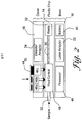
- FIG 2 is a schematic view of the illustrative portable cytometer of Figure 1 .
- the base 16 may include an array of light sources 22, associated optics and the necessary control and processing electronics 40 for operation of the cytometer.
- the base 16 may also include a battery 42 for powering the cytometer.
- the cover 12 is shown having a manual pressurizing element 44, pressure-chambers 46a, 46b and 46c with control microvalves, and an array of light detectors 24 with associated optics.
- the removable cartridge 14 may receive a sample fluid via the sample collector port 32. When pressurized by the cover 18, the removable cartridge 14 performs blood dilution, red cell lysing, and hydrodynamic focusing for core formation in a preferred embodiment.
- the core is provided down a flow stream path 50, which passes the flow stream window 30 of Figure 1 .
- the array of light sources 22 and associated optics in the base provide light through the core stream via the flow stream window 30.
- the array of light detectors and associated optics receive scattered and non-scattered light from the core, also via the flow stream window 30.
- the controller or processor 40 receives output signals from the array of detectors, and differentiates and counts selected white blood cells that are present in the core stream.
- the removable cartridge 14 may include a fluid control block 48 for helping to control the velocity of each of the fluids.
- the fluid control block 48 includes flow sensors for sensing the velocity of the various fluids and report the velocities to the controller or processor 40. The controller or processor 40 may then adjust the microvalves associated with pressure-chambers 46a, 46b and 46c to achieve the desired pressures and thus desired fluid velocities for proper operation of the cytometer.
- one or more electrical, optical and/or wireless connections may be provided between the processor 40 in the base 16 and the flow sensors on the removable cartridge 14.
- the removable cartridge 14 preferably has a waste reservoir 52 downstream of the flow stream window 30.
- the waste reservoir 52 receives and stores the fluid of the flow stream in the removable cartridge 14.
- the removable cartridge may be removed and disposed of, preferably in a container compatible with biological waste.
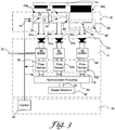
- Figure 3 is a more detailed schematic diagram showing the portable cytometer of Figure 2 with the cover 18 not yet depressed.
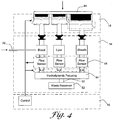
- Figure 4 is a more detailed schematic diagram showing the portable cytometer of Figure 2 with the cover depressed.
- the cover 18 is shown having a manual pressurizing element 44, pressure-chambers 46a, 46b and 46c, and control microvalves generally shown at 60.
- the array of light sources and detectors are not shown in these Figures.
- pressure chamber 46a provides pressure to a blood sample reservoir 62
- pressure chamber 46b provides pressure to a lyse reservoir 64
- pressure chamber 46c provides pressure to a sheath reservoir 66.
- the size and shape of each pressure chamber 46a, 46b and 46c may be tailored to provide the desired pressure characteristics to the corresponding fluid.
- Pressure chamber 46a includes a first pressure chamber 70 and a second pressure chamber 72.
- a first valve 74 is provided between the first pressure chamber 70 and the second pressure chamber 72 for controllably releasing the pressure in the first pressure chamber 70 to a second pressure chamber 72.
- a second valve 76 in fluid communication with the second pressure chamber 72, controllably vents the pressure in the second pressure chamber 72.
- Each valve is preferably an array of electrostatically actuated microvalves that are individually addressable and controllable, as described in, for example, co-pending U.S. Patent Application Serial Number 09/404,560 , entitled "ADDRESSABLE VALVE ARRAYS FOR PROPORTIONAL PRESSURE OR FLOW CONTROL".
- Pressure chambers 46b and 46c include similar valves to control the pressures applied to the lyse reservoir 64 and sheath reservoir 66, respectively.
- each valve may be an array of electrostatically actuated microvalves that are pulse modulated with a controllable duty cycle to achieve a controlled "effective" flow or leak rate.
- each valve may be a similar to that described in co-pending U.S. Patent Application Serial Number 1100.1174101, entitled “ELECTROSTATICALLY ACTUATED VALVE".
- the removable cartridge 14 has pressure receiving ports 34a, 34b, and 34c for receiving the controlled pressures from the cover 18.
- the controlled pressures are provided to the blood reservoir 62, lyse reservoir 64 and sheath reservoir 66, as shown.
- the lyse reservoir 64 and sheath reservoir 66 are preferably filled before the removable cartridge 14 is shipped for use, while the blood reservoir 62 is filled from sample collector port 32.
- a blood sample may be provided to the sample collector port 32, and through capillary action, the blood sample may be drawn into the blood reservoir 62. Once the blood sample is in the blood reservoir 62, the cover 18 may be closed and the system may be pressurized.
- a flow sensor is provided in-line with each fluid prior to hydrodynamic focussing.
- Each flow sensor 80, 100 and 102 measures the velocity of the corresponding fluid.
- the flow sensors are preferably thermal anemometer type flow sensors, and more preferably microbridge or microbrick type flow sensor.
- Microbridge flow sensors are described in, for example, U.S. Patent No. 4,478,076 , U.S. Patent No. 4,478,077 , U.S. Patent No. 4,501,144 , U.S. Patent No. 4,651,564 , U.S. Patent No.4,683,159 , and U.S. Patent No. 5,050429 .
- An output signal from each flow sensor 80, 100 and 102 is provided to controller or processor 40 via one or more electrical connection between the removable cartridge and the base.
- one or more optical transmitters and/or optical receivers may be provided on the removable cartridge 14. The one or more optical transmitters and/or optical receivers may be used to, for example, help provide optical communication between the removable cartridge 14 and the controller or processor 40 in the base 16.
- one or more RF transmitters and/or receivers may be provided on or in the removable cartridge. The one or more RF transmitters and/or receivers may be used to, for example, help provide wireless communication between the removable cartridge and the base 16.
- the controller or processor 40 opens the first valve 74 when the velocity of the blood sample drops below a first predetermined value and opens the second valve 76 when the velocity of the blood sample increases above a second predetermined value.
- Valves 84, 86, 94 and 96 operate in a similar manner to control the velocities of the lyse and sheath fluids.
- the manual pressurizing element 44 During operation, and to pressurize the system, the manual pressurizing element 44 is depressed.
- the manual pressurizing element 44 includes three plungers, with each plunger received within a corresponding one of the first pressure chambers.
- the plungers create a relatively high non-precision pressure in the first pressure chambers.
- Lower, controlled pressures are built in the secondary chambers by opening the first valves 70, 84 and 94, which produce a controllable leak into the secondary chambers. If two much pressure builds up in the secondary pressure chambers, the corresponding vent valve 76, 86 and 96 are opened to relieve the pressure.
- the normally open first valves 74, 84 and 94 are closed while the vent valves 76, 86 and 96 are open.
- a predetermined pressure P is achieved in the first pressure chambers
- the vent valves 76, 86 and 96 are closed, and the first valves 74, 84 and 94 are opened to build a lower pressure P' in the secondary pressure chambers.
- the controlled pressure in the secondary pressure chambers provide the necessary pressures to the fluidic circuit of the removable cartridge 14 to produce fluid flow for the blood, lyse and sheath.
- the velocity of the fluid flow is then measured by the downstream flow sensors 80, 100 and 102.
- Each flow sensor provides an output signal that is used by the controller or processor 40 to control the operation of the corresponding first valve and vent valve to provide a desired and constant flow rate for each fluid.
- Downstream valves generally shown at 110 may also be provided. Controller or processor 40 may close downstream valves 110 until the system is pressurized. This may help prevent the blood, lyse and sheath from flowing into the fluid circuit before the circuit is pressurized. In another embodiment, downstream valves 110 are opened by mechanical action when the cover is closed.
- pressure generated in pressure-chambers 46a, 46b or 46c, or some other pressure chamber may be used to control one or more pneumatic valves placed on or in the removable cartridge 14.
- the one or more pneumatic valves may be used to control, for example, a flow path, a flow rate or some other flow property associated with a fluid or gas on or in the removable cartridge 14.
- the pressure generated in pressure-chambers 46a, 46b or 46c, or some other pressure chamber may be used to control one or more pneumatically controlled elements that provide some other mechanical movement on or in the removable cartridge 14, such as a pneumatically controlled pump, plunger, gear, etc.
- FIG. 5 is a perspective view of another illustrative portable cytometer in accordance with the present invention.
- the basic operation of the portable cytometer of Figure 5 is similar to that described above with respect to Figures 1-4 above.
- the portable cytometer of Figure 5 is generally shown at 120, and includes a base 122, a first member 124, a second member 126, a clamp frame 128 with clamp lever 130, an air buffer module 132, a valve module assembly 134 with polymer microvalves, an air accumulator module 136, and an optics assembly 140.
- the second member 126 is fixed to the base 122.
- a number of shoulder screws 142a, 142b, 142c and 142d pass through holes in the first member 124 and are secured to the second member 126.
- Springs 144a, 144b, 144c and 144d (144d not shown in Figure 5 ) are placed between the first member 124 and the head of the corresponding shoulder screw 142a, 142b, 142c and 142d.
- the springs 144a, 144b, 144c and 144d provide a bias force to the first member 124 toward the second member 126.
- the clamp frame 128 is secured to the second member 126 as shown.
- the clamp lever 130 interacts with the clamp frame to provide an outward bias force to the first member away from the second member 126.
- the first member 124 is moved away from the second member 126 by overcoming the inward bias force provided of spring 144a, 144b, 144c and 144d.
- the clamp lever 130 moves the clamp lever 130 in a second opposite direction, the first member 124 is moved toward the second member 126, assisted by the inward bias force provided of spring 144a, 144b, 144c and 144d.
- the clamp lever 130 may be moved in the first direction to move the first member 124 away from the second member 126, leaving a space therebetween.
- a removable media member such as a removable fluidic cartridge 150, may then be slid into the space.
- the removable cartridge 150 may have a front side, a back side, and one or more lateral sides extending between the front side and the back side, as shown.
- the clamp lever 130 may then be moved in the second direction to move the first member 124 toward the second member 136 to secure and/or engage the removable media member 150, as shown in Figure 5 .
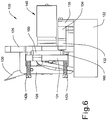
- Figure 6 is a perspective side view of the illustrative portable cytometer of Figure 5 .
- the removable media member 150 has one or more fluid ports in the front and/or back sides, similar to that described above with respect to Figures 1-4 . It is contemplated that the one or more fluid ports may be adapted to accept either a gas or a liquid, depending on the application.
- the second member 126 of the illustrative embodiment includes corresponding fluid ports that align with the one or more fluid ports of the removable media member 150. One such fluid port is shown at 160 in Figure 6 .
- a fluid port gasket (see Figure 12 below) may be secured to the second member 126 to help provide a better seal, if desired.
- a fluid control module may then be fluidly coupled to the fluid ports of the second member 126.
- the fluid control module includes the air accumulator module 136, the valve module assembly 134 with polymer microvalves, and the air buffer module 132.
- the air accumulator module 136 includes an internal chamber for accumulating air pressure.
- a port (not shown) may be provided from the internal chamber of the air accumulator 136 to an air pressure source.
- the accumulated air pressure may be supplied to the valve module assembly 134.
- the valve module assembly may include one or more microvalves, such as polymer microvalves as disclosed in U.S. Patent Application Serial Number 1100.1174101 , entitled "ELECTROSTATICALLY ACTUATED VALVE".
- the valve module assembly 134 may provide three separate pressure channels including a blood channel, a lyse channel and a sheath channel, as shown and described above with respect to Figures 1-4 .
- the valve module assembly 134 is preferably controlled by a controller in base 122 to provide three separate controlled pressures to air buffer module 132.
- Air buffer module 132 buffers the controlled pressures, and delivers the pressurized air to the fluid ports of the removable media member 150 via the fluid ports that pass in or through the second member 126.
- the removable media member 150 may include one or more electrical and/or optical devices.
- the removable media member 150 may include three flow sensors, with each flow sensor measuring the flow rate of the pressurized fluid through one of the three separate pressure channels of the removable media member 150.
- the flow sensors are preferably thermal anemometer type flow sensors, and more preferably microbridge or microbrick type flow sensor, commercially available from Honeywell International. Microbridge flow sensors are described in, for example, U.S. Patent No. 4,478,076 , U.S. Patent No. 4,478,077 , U.S. Patent No. 4,501,144 , U.S. Patent No. 4,651,564 , U.S.
- Patent No.4,683,159 and U.S. Patent No. 5,050429 .
- An output signal from each flow sensor is provided to controller or processor in base 122, preferably via an electrical, optical and/or wireless coupling between the removable media member and the second member 126.
- the optical assembly module 140 preferably includes one or more light sources (e.g. VCSELs) on one side of the removable cartridge 150, one or more light detectors on the opposite side of the removable cartridge 150, and associated optics.
- the removable cartridge 150 may include a transparent flow stream window, which is in alignment with the one or more light sources and one or more light detectors.
- the air buffer module 132, valve module assembly 134, and air accumulator module 136 are preferably controlled to form a core stream down a flow stream path that passes the flow stream window in the removable cartridge 150.
- the light sources when activated, provide light through the core stream via one side of the flow stream window.
- the optical detectors receive scattered and non-scattered light from the core stream via the opposite side of the flow stream window.
- a controller or processor in the base 122 then receives output signals from the detectors, and differentiates and counts selected white blood cells that are present in the core stream.
- Figure 7 is another perspective view of the illustrative portable cytometer of Figure 5 , further illustrating additional detail.
- Figure 7 shows a hole 170 through the first member 124 and second member 126.
- the hole 170 may allow the one or more light sources and one or more light detectors of the optical assembly module 140 to directly access the flow stream window of the removable cartridge (not shown in Figure 7 ).
- Figure 7 also shows one or more spring biased probes secured to the first member 124.
- the one or more spring biased probes are preferably positioned to align with the one or more electrical contact pads on the removable cartridge when the removable cartridge is at a desired positioned between the first member 124 and the second member 126.
- three arrays of spring biased probes 174a, 174b and 174c are provided, with each array mounted via a small PC board and secured within a corresponding hole in the first member 124.
- the holes in the first member 124 may provide access to the reverse side of the spring bias probes, which in some embodiments, may provide a convenient location to make an electrical connection between a controller in the base 122 and each spring bias probe.
- one or more optical transmitters and/or optical detectors may be secured to the first and/or second member.
- the one or more optical transmitters and/or optical detectors are preferably positioned to align with the one or more optical detectors and/or optical transmitters on the removable cartridge when the removable cartridge is at a desired positioned between the first member 124 and the second member 126. This may provide an optical link between the removable cartridge and the first member and/or second member 126, as desired.
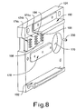
- FIG 8 is a perspective view of the first member 124 of the illustrative portable cytometer of Figure 5 .
- Figure 8 shows the opposite side of the three arrays of spring biased probes 174a, 174b and 174c of Figure 7 .
- each spring bias probes is biased by a spring in an outward direction away from the first member 124 and toward the removable cartridge (not shown in Figure 8 ).
- the spring biased probes are preferably positioned to align with the one or more electrical contact pads on the removable cartridge when the removable cartridge is at a desired positioned between the first member 124 and the second member 126.
- the spring biased probes preferably make electrical contact with the one or more electrical contact pads on the removable cartridge.
- an outward or separating bias 178 may be provided between the first member 124 and the removable cartridge.
- the outward bias 178 may include a wedge 180 and a spring 182.
- the spring 182 may be positioned in a recess 184 in the first member 124, with the wedge 180 biased in an outward direction by the spring 182.
- the outward bias 178 may be overcome when the first member 124 and the second member 126 are moved toward each other to secure and/or engage the removable cartridge. However, when the first member 124 and the second member 126 are moved away from each other to release the removable cartridge, the outward bias 178 may separate the one or more spring biased probes 174a, 174b and 174c from the one or more electrical contact pads of the removable cartridge, which may make the removal of the removable cartridge from between the first member 124 and the second member 126 easier and may help protect the spring bias probes from damage during the removal process.
- the first member 124 may also have one or more L-shaped cleats that provide a slot to receive the removable cartridge.
- an upper L-shaped cleat 190 and a lower L-shaped cleat 192 are provided.
- the L-shaped cleats 190 and 192 may each include, for example, a first leg 194 that extends away from the first member 124 and toward the second member, and a second leg 196 that extends from a distal end of the first leg 194 and in a perpendicular direction relative to the first leg 194 so that a channel or receiving slot 198 is formed.
- the channel or receiving slot 198 may then receive one side of the removable media member.
- the upper L-shaped cleat 190 includes a second leg 196 that extends in a downward direction
- the lower L-shaped cleat 192 includes a second leg that extends in an upward direction
- the upper L-shaped cleat 190 and the lower L-shaped cleat 192 are spaced so that two spaced channels 196 are provided for receiving opposing sides (e.g. upper side and lower side) of the removable cartridge. That is, the channel or slot of the upper L-shaped cleat 190 and the channel or slot of the lower L-shaped cleat 192 are arranged so that the removable cartridge slides into both channels when it is inserted between the first member 124 and the second member 126.
- the two L-shaped cleats are secured to the first member 124.
- An alignment pin 200 may be provided toward the back of the first member 124 to engage the back of the removable cartridge.
- the alignment pin 200 is preferably positioned to stop the removable cartridge at or near the desired insertion position between the first member 124 and the second member 126.
- the first member 124 and the second member 126 may be moved away from one another, and the removable cartridge may be slid into the channel or receiving slots 198 provided by the L-shaped cleats 190 and 192 until the removable cartridge engages the alignment pin 200.
- the L-shaped cleats 190 and 192 are preferably positioned so that that when the removable cartridge is received by the L-shaped cleats 190 and 192, the removable cartridge is at least roughly aligned with a desired position relative to the first member 124 and/or second member 126.
- the first member 124 and the second member 126 may then be moved toward one another to engage and/or secure the removable cartridge therebetween.
- the first member 124 and the second member 126 may be moved away from each other. Because the upper and lower edges of the removable cartridge are positioned in the channel or slot 198 of the L-shaped cleats 190 and 192, the removable cartridge is pulled away from the second member 126 by the second legs 196 of the L-shaped cleats 190 and 192 as the first member 124 and second member 126 are moved away from each other.
- the second member 126 may include one or more alignment pins 200a-200c that extend toward the first member (see Figure 12 ).
- the removable media member 150 may then include one or more receiving holes for receiving the one or more alignment pins 200a-200c.
- the alignment pins 200a-200c and receiving holes may provide improved alignment between the removable media member 150 and the first member 124 and/or second member 126 when the removable media member 150 is secured between the first member 124 and the second member 126.
- the L-shaped cleats 190 and 192 may be used to pull the removable media member 150 away from the second member 126, thereby separating the one or more receiving holes of the removable media member 150 from the one or more alignment pins 200a-200c that are extending from the second member 126. With the one or more receiving holes separated from the alignment pins 200a-200c, the removable media member 150 then may be more easily removed from between the first member 124 and the second member 126.
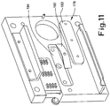
- FIG 9 is a perspective view of the lower cleat 192 of Figure 8 .
- the illustrative lower cleat 192 includes a first leg 194a and a second leg 196a, wherein the second leg 196a extends from a distal end of the first leg 194a and in a perpendicular direction to form a channel or receiving slot 198a.
- a mounting leg 202a may extend from the first leg 194 as shown, for mounting the lower cleat 192 to the first member 124.
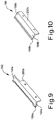
- FIG 10 is a perspective view of the upper cleat 190 of Figure 8 .
- the illustrative upper cleat 190 includes a first leg 194b and a second leg 196b, wherein the second leg 196b extends from a distal end of the first leg 194b and in a perpendicular direction to form a channel or receiving slot 198b.
- a mounting leg 202b may extend from the first leg 194b as shown, for mounting the upper cleat 190 to the first member 124.
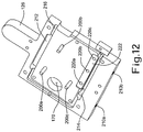
- Figure 12 is a perspective view of the second plate or member 126 of the illustrative portable cytometer of Figure 5 .
- the second member 126 may be fixed to the base 122 by screws that are threaded into screw holes 210a and 210b.
- the second member 126 may further include a hole 170 that may allow the one or more light sources and one or more light detectors of the optical assembly module 140 to directly access the flow stream window of the removable cartridge.
- the second member 126 includes a flat major surface with a recessed portion for receiving the removable cartridge.
- the second member 126 may include one or more alignment pins 200a-200c that extend toward the first member.
- the removable cartridge 150 may then include one or more receiving holes for receiving the one or more alignment pins 200a-200c.
- the alignment pins 200a-200c and receiving holes may provide improved alignment between the removable cartridge and the first member 124 and/or second member 126 when the removable cartridge is secured between the first member 124 and the second member 126.
- Additional recesses 212 and 214 may be included to receive the second legs 196a and 196b of the upper L-shaped cleat 190 and lower L-shaped cleat 192, respectively (see Figures 8-10 ). By providing relief for the second legs 196a and 196b of the upper L-shaped cleat 190 and lower L-shaped cleat 192, the removable cartridge may directly engage the surface of the second member 126.
- the manufacture of the removable cartridge may create a ridge, a burr, or other imperfections, particularly around the outer perimeter of the removable cartridge.
- a fluidic cartridge may be manufactured by laminating several layers or sheets together, and then cutting individual fluidic cartridges from the laminated structure. At the cut lines, ridges, burrs, and/or other imperfections may arise.
- a groove 216 or other relief structure may be provided in the receiving surface of the second member 126 to accommodate the one or more imperfections in the removable cartridge.
- a groove 216 may extend along a groove path that extends around the perimeter of the removable cartridge.
- a groove or other relief structure may be provided at any location where an anticipated imperfection might occur in the removable cartridge. It is also contemplated that a groove or other relief structure may be provided in the receiving surface of the first member 124, if desired.
- the removable cartridge has one or more fluid ports, similar to that described above with respect to Figures 1-4 . It is contemplated that the one or more fluid ports may be adapted to accept either a gas or a liquid, depending on the application.
- the second member 126 of the illustrative embodiment includes corresponding fluid ports 220a-220c that align with the one or more fluid ports of the removable cartridge.
- a fluid port gasket 222 may be secured to the second member 126 to help provide a better seal, if desired.
Landscapes
- Chemical & Material Sciences (AREA)
- Dispersion Chemistry (AREA)
- Physics & Mathematics (AREA)
- Health & Medical Sciences (AREA)
- Life Sciences & Earth Sciences (AREA)
- Analytical Chemistry (AREA)
- Biochemistry (AREA)
- General Health & Medical Sciences (AREA)
- General Physics & Mathematics (AREA)
- Immunology (AREA)
- Pathology (AREA)
- Automatic Analysis And Handling Materials Therefor (AREA)
- Mechanical Coupling Of Light Guides (AREA)
Applications Claiming Priority (5)
| Application Number | Priority Date | Filing Date | Title |
|---|---|---|---|
| US40487602P | 2002-08-21 | 2002-08-21 | |
| US404876P | 2002-08-21 | ||
| US10/612,664 US7000330B2 (en) | 2002-08-21 | 2003-07-02 | Method and apparatus for receiving a removable media member |
| US612664 | 2003-07-02 | ||
| PCT/US2003/025779 WO2004019013A2 (en) | 2002-08-21 | 2003-08-15 | Method and apparatus for receiving a removable media member |
Publications (2)
| Publication Number | Publication Date |
|---|---|
| EP1556680A2 EP1556680A2 (en) | 2005-07-27 |
| EP1556680B1 true EP1556680B1 (en) | 2020-04-01 |
Family
ID=31949875
Family Applications (1)
| Application Number | Title | Priority Date | Filing Date |
|---|---|---|---|
| EP03793098.9A Expired - Lifetime EP1556680B1 (en) | 2002-08-21 | 2003-08-15 | Method and apparatus for receiving a removable media member |
Country Status (6)
| Country | Link |
|---|---|
| US (1) | US7000330B2 (enExample) |
| EP (1) | EP1556680B1 (enExample) |
| JP (1) | JP4171744B2 (enExample) |
| CN (1) | CN1688875B (enExample) |
| AU (1) | AU2003258281A1 (enExample) |
| WO (1) | WO2004019013A2 (enExample) |
Families Citing this family (30)
| Publication number | Priority date | Publication date | Assignee | Title |
|---|---|---|---|---|
| US8518328B2 (en) * | 2005-12-27 | 2013-08-27 | Honeywell International Inc. | Fluid sensing and control in a fluidic analyzer |
| US8383043B2 (en) | 2004-05-14 | 2013-02-26 | Honeywell International Inc. | Analyzer system |
| US7641856B2 (en) * | 2004-05-14 | 2010-01-05 | Honeywell International Inc. | Portable sample analyzer with removable cartridge |
| US7061595B2 (en) | 2000-08-02 | 2006-06-13 | Honeywell International Inc. | Miniaturized flow controller with closed loop regulation |
| EP3270156A1 (en) | 2004-04-07 | 2018-01-17 | Abbott Laboratories | Disposable chamber for analyzing biologic fluids |
| US8323564B2 (en) * | 2004-05-14 | 2012-12-04 | Honeywell International Inc. | Portable sample analyzer system |
| US8097225B2 (en) * | 2004-07-28 | 2012-01-17 | Honeywell International Inc. | Microfluidic cartridge with reservoirs for increased shelf life of installed reagents |
| US7333197B2 (en) * | 2004-11-17 | 2008-02-19 | Honeywell International Inc. | Raman detection based flow cytometer |
| US20070045128A1 (en) * | 2005-08-19 | 2007-03-01 | Honeywell International Inc. | Chlorine dioxide sensor |
| US7731901B2 (en) | 2005-10-19 | 2010-06-08 | Abbott Laboratories | Apparatus and method for performing counts within a biologic fluid sample |
| US7485153B2 (en) * | 2005-12-27 | 2009-02-03 | Honeywell International Inc. | Fluid free interface for a fluidic analyzer |
| US8182767B2 (en) * | 2005-12-27 | 2012-05-22 | Honeywell International Inc. | Needle-septum interface for a fluidic analyzer |
| WO2007111906A2 (en) * | 2006-03-22 | 2007-10-04 | Wms Gaming Inc. | Wagering game machine with a toolless hard drive mount |
| WO2007115378A1 (en) * | 2006-04-11 | 2007-10-18 | Minifab (Australia) Pty Ltd | Microfluidic package housing |
| WO2008049447A1 (en) | 2006-10-25 | 2008-05-02 | Fraunhofer-Gesellschaft Zur Foerderung Der Angewandten Forschung E.V. | Chip holder, fluidic system and chip holder system |
| US20090038171A1 (en) * | 2007-08-08 | 2009-02-12 | International Business Machines Corporation | Alignment tool for assembly of microprocessor board to server chassis |
| US9034277B2 (en) | 2008-10-24 | 2015-05-19 | Honeywell International Inc. | Surface preparation for a microfluidic channel |
| CN106110923A (zh) | 2009-12-18 | 2016-11-16 | 艾博特健康公司 | 生物流体样本分析卡盒 |
| WO2012092593A1 (en) | 2010-12-30 | 2012-07-05 | Abbott Point Of Care, Inc. | Biologic fluid analysis cartridge with sample handling portion and analysis chamber portion |
| US8951781B2 (en) | 2011-01-10 | 2015-02-10 | Illumina, Inc. | Systems, methods, and apparatuses to image a sample for biological or chemical analysis |
| CN202649594U (zh) * | 2011-01-10 | 2013-01-02 | 伊鲁米那股份有限公司 | 光学组件、激发光模块以及光学成像系统 |
| EP2748618A1 (en) | 2011-08-24 | 2014-07-02 | Abbott Point of Care Inc. | Biologic fluid sample analysis cartridge |
| US9207166B2 (en) * | 2013-01-31 | 2015-12-08 | Honeywell International Inc. | Micro-molded cytometer cartridge with integrated optics |
| WO2015138818A1 (en) * | 2014-03-12 | 2015-09-17 | Theranos, Inc. | Systems, devices, and methods for bodily fluid sample collection |
| US10471425B2 (en) * | 2017-02-16 | 2019-11-12 | International Business Machines Corporation | Automated machine for sorting of biological fluids |
| US11067526B2 (en) | 2017-08-17 | 2021-07-20 | Abbott Point Of Care Inc. | Devices, systems, and methods for performing optical and electrochemical assays |
| WO2019035077A1 (en) | 2017-08-17 | 2019-02-21 | Abbott Point Of Care Inc. | DEVICES, SYSTEMS AND METHODS FOR PERFORMING OPTICAL ASSAYS |
| CN111774115B (zh) * | 2020-05-29 | 2021-09-07 | 东南大学 | 一种用于固定带电极微流控芯片的夹具装置 |
| CN120303559A (zh) * | 2022-10-21 | 2025-07-11 | 普罗比斯蒂斯公司 | 模块化分析物感测系统 |
| WO2024247490A1 (ja) * | 2023-05-30 | 2024-12-05 | 株式会社ジャパンディスプレイ | 画像取得装置 |
Family Cites Families (113)
| Publication number | Priority date | Publication date | Assignee | Title |
|---|---|---|---|---|
| US2403692A (en) | 1944-12-29 | 1946-07-09 | George C Tibbetts | Piezoelectric device |
| US2975307A (en) | 1958-01-02 | 1961-03-14 | Ibm | Capacitive prime mover |
| US3304446A (en) | 1963-12-26 | 1967-02-14 | Union Oil Co | Electrostrictive fluid transducer |
| US3414010A (en) | 1965-11-01 | 1968-12-03 | Honeywell Inc | Control apparatus |
| US3381623A (en) | 1966-04-26 | 1968-05-07 | Harold F Elliott | Electromagnetic reciprocating fluid pump |
| CH511476A (de) | 1968-10-08 | 1971-03-15 | Proctor Ets | Vorrichtung zum Erzeugen von periodischen, mechanischen Schwingungen in einem Uhrwerk |
| US3726296A (en) | 1971-08-09 | 1973-04-10 | Process Systems | Fluidic control system and method for calibrating same |
| JPS4829420A (enExample) | 1971-08-20 | 1973-04-19 | ||
| US3803424A (en) | 1972-05-08 | 1974-04-09 | Physics Int Co | Piezoelectric pump system |
| JPS5146965Y2 (enExample) | 1972-06-17 | 1976-11-12 | ||
| US3827457A (en) | 1973-06-22 | 1974-08-06 | Westinghouse Air Brake Co | Fluid pressure system for converting digital signals to analog signals |
| US3976862A (en) | 1975-03-18 | 1976-08-24 | Block Engineering, Inc. | Flow stream processor |
| GB1530662A (en) | 1976-03-01 | 1978-11-01 | Mullard Ltd | Peristaltic pump |
| US4244109A (en) * | 1976-10-19 | 1981-01-13 | Pertec Computer Corporation | Apparatus for mounting and aligning printed circuit board |
| US4197737A (en) | 1977-05-10 | 1980-04-15 | Applied Devices Corporation | Multiple sensing device and sensing devices therefor |
| US4140936A (en) | 1977-09-01 | 1979-02-20 | The United States Of America As Represented By The Secretary Of The Navy | Square and rectangular electroacoustic bender bar transducer |
| SU744877A1 (ru) | 1978-01-09 | 1980-06-30 | Институт математики СО АН СССР | Электростатический двигатель с возвратно-поступательным движением |
| IL59942A (en) | 1980-04-28 | 1986-08-31 | D P Lab Ltd | Method and device for fluid transfer |
| DE3108693A1 (de) | 1981-03-07 | 1982-09-23 | Walter Ing.(grad.) 7758 Meersburg Holzer | Elektromagnetventil, insbesondere fuer hausgeraete |
| US4498112A (en) | 1982-03-22 | 1985-02-05 | Data Electronics, Inc. | Tape cartridge receptacle |
| US4453169A (en) | 1982-04-07 | 1984-06-05 | Exxon Research And Engineering Co. | Ink jet apparatus and method |
| US4478076A (en) | 1982-09-30 | 1984-10-23 | Honeywell Inc. | Flow sensor |
| US4478077A (en) | 1982-09-30 | 1984-10-23 | Honeywell Inc. | Flow sensor |
| US4501144A (en) | 1982-09-30 | 1985-02-26 | Honeywell Inc. | Flow sensor |
| US4651564A (en) | 1982-09-30 | 1987-03-24 | Honeywell Inc. | Semiconductor device |
| US4683159A (en) | 1982-09-30 | 1987-07-28 | Honeywell Inc. | Semiconductor device structure and processing |
| US4539614A (en) | 1983-05-18 | 1985-09-03 | Drivetec, Inc. | Flexible magnetic disk clamping an injector mechanism |
| DE3320441A1 (de) | 1983-06-06 | 1984-12-06 | Siemens AG, 1000 Berlin und 8000 München | Mit fluessigkeitstroepfchen arbeitendes schreibgeraet mit an beiden enden starr mit einer duesenplatte verbundenen stabfoermigen piezoelektrischen wandlern |
| DE3515499C2 (de) | 1984-05-01 | 1994-08-04 | Smc Kk | Elektropneumatischer Wandler |
| US4673995A (en) | 1984-07-06 | 1987-06-16 | Kennedy Company | Cartridge tape drive with friction roller to open cartridge door |
| US4576050A (en) | 1984-08-29 | 1986-03-18 | General Motors Corporation | Thermal diffusion fluid flow sensor |
| US4654546A (en) | 1984-11-20 | 1987-03-31 | Kari Kirjavainen | Electromechanical film and procedure for manufacturing same |
| JPS61123868A (ja) * | 1984-11-21 | 1986-06-11 | キヤノン株式会社 | パネル基板の位置合せ保証方法 |
| JPS61173319A (ja) | 1985-01-26 | 1986-08-05 | Shoketsu Kinzoku Kogyo Co Ltd | 流体用レギユレ−タ |
| US4756508A (en) | 1985-02-21 | 1988-07-12 | Ford Motor Company | Silicon valve |
| US4745279A (en) | 1986-01-02 | 1988-05-17 | American Hospital Supply Corporation | Hematocrit measuring apparatus |
| JPH0729414B2 (ja) | 1987-01-22 | 1995-04-05 | 株式会社テック | 弁素子及びその製造方法 |
| US4874949A (en) | 1987-09-14 | 1989-10-17 | Vanderbilt University | Method of measuring lung vascular function and transcapillary transport by the use of nonradioactive markers |
| JPH01174278A (ja) | 1987-12-28 | 1989-07-10 | Misuzu Erii:Kk | インバータ |
| US4911616A (en) | 1988-01-19 | 1990-03-27 | Laumann Jr Carl W | Micro miniature implantable pump |
| US4938742A (en) | 1988-02-04 | 1990-07-03 | Smits Johannes G | Piezoelectric micropump with microvalves |
| US5065978A (en) | 1988-04-27 | 1991-11-19 | Dragerwerk Aktiengesellschaft | Valve arrangement of microstructured components |
| JP2709318B2 (ja) | 1988-08-31 | 1998-02-04 | セイコープレシジョン株式会社 | 液晶パネルおよび液晶パネルを用いた変換装置 |
| JPH0286258A (ja) | 1988-09-21 | 1990-03-27 | Nec Corp | 信号検出回路 |
| CH679555A5 (enExample) | 1989-04-11 | 1992-03-13 | Westonbridge Int Ltd | |
| JPH04501449A (ja) | 1989-06-14 | 1992-03-12 | ウエストンブリッジ インターナショナル リミティド | マイクロポンプ |
| US5069419A (en) | 1989-06-23 | 1991-12-03 | Ic Sensors Inc. | Semiconductor microactuator |
| DE3925749C1 (enExample) | 1989-08-03 | 1990-10-31 | Fraunhofer-Gesellschaft Zur Foerderung Der Angewandten Forschung Ev, 8000 Muenchen, De | |
| DE3926066A1 (de) | 1989-08-07 | 1991-02-14 | Ibm Deutschland | Mikromechanische kompressorkaskade und verfahren zur druckerhoehung bei extrem niedrigem arbeitsdruck |
| CH681168A5 (en) | 1989-11-10 | 1993-01-29 | Westonbridge Int Ltd | Micro-pump for medicinal dosing |
| US5171132A (en) | 1989-12-27 | 1992-12-15 | Seiko Epson Corporation | Two-valve thin plate micropump |
| US5096388A (en) | 1990-03-22 | 1992-03-17 | The Charles Stark Draper Laboratory, Inc. | Microfabricated pump |
| EP0483469B1 (en) | 1990-10-30 | 1994-10-12 | Hewlett-Packard Company | Micropump |
| DE69129260T2 (de) | 1990-11-03 | 1998-11-19 | Horiba Ltd | Gerät zur Messung der Teilchengrössenverteilung |
| US5206557A (en) | 1990-11-27 | 1993-04-27 | Mcnc | Microelectromechanical transducer and fabrication method |
| DE4119955C2 (de) | 1991-06-18 | 2000-05-31 | Danfoss As | Miniatur-Betätigungselement |
| US5176358A (en) | 1991-08-08 | 1993-01-05 | Honeywell Inc. | Microstructure gas valve control |
| US5192197A (en) | 1991-11-27 | 1993-03-09 | Rockwell International Corporation | Piezoelectric pump |
| JP3144500B2 (ja) | 1992-02-10 | 2001-03-12 | 富士電機株式会社 | 静電式アクチュエータ |
| JPH0678566A (ja) | 1992-08-25 | 1994-03-18 | Kanagawa Kagaku Gijutsu Akad | 静電アクチュエータ |
| US5441597A (en) | 1992-12-01 | 1995-08-15 | Honeywell Inc. | Microstructure gas valve control forming method |
| JPH06338116A (ja) | 1993-03-31 | 1994-12-06 | Canon Inc | 光学的情報記録/再生装置 |
| US5642015A (en) | 1993-07-14 | 1997-06-24 | The University Of British Columbia | Elastomeric micro electro mechanical systems |
| US5368704A (en) | 1993-08-06 | 1994-11-29 | Teknekron Corporation | Micro-electrochemical valves and method |
| JPH07184377A (ja) | 1993-10-21 | 1995-07-21 | Mitsubishi Chem Corp | 静電アクチュエータ |
| US5499909A (en) | 1993-11-17 | 1996-03-19 | Aisin Seiki Kabushiki Kaisha Of Kariya | Pneumatically driven micro-pump |
| DE69410487T2 (de) | 1993-12-28 | 1998-11-05 | Westonbridge Int Ltd | Mikropumpe |
| CH689836A5 (fr) | 1994-01-14 | 1999-12-15 | Westonbridge Int Ltd | Micropompe. |
| DE4402119C2 (de) | 1994-01-25 | 1998-07-23 | Karlsruhe Forschzent | Verfahren zur Herstellung von Mikromembranpumpen |
| GB9406551D0 (en) | 1994-03-31 | 1994-05-25 | Hjelm Nils M | Chromatography system and methodology |
| US5585069A (en) | 1994-11-10 | 1996-12-17 | David Sarnoff Research Center, Inc. | Partitioned microelectronic and fluidic device array for clinical diagnostics and chemical synthesis |
| US5601080A (en) | 1994-12-28 | 1997-02-11 | Coretech Medical Technologies Corporation | Spectrophotometric blood analysis |
| US5793485A (en) | 1995-03-20 | 1998-08-11 | Sandia Corporation | Resonant-cavity apparatus for cytometry or particle analysis |
| US5788833A (en) | 1995-03-27 | 1998-08-04 | California Institute Of Technology | Sensors for detecting analytes in fluids |
| US5571401A (en) | 1995-03-27 | 1996-11-05 | California Institute Of Technology | Sensor arrays for detecting analytes in fluids |
| US5528045A (en) | 1995-04-06 | 1996-06-18 | Becton Dickinson And Company | Particle analyzer with spatially split wavelength filter |
| US5869916A (en) | 1995-05-26 | 1999-02-09 | Asmo Co., Ltd. | Electrostatic actuator with different electrode spacing |
| US5716852A (en) | 1996-03-29 | 1998-02-10 | University Of Washington | Microfabricated diffusion-based chemical sensor |
| EP0871539B1 (en) | 1995-06-16 | 2002-02-20 | University of Washington | Tangential flow planar microfabricated fluid filter |
| WO1997000442A1 (en) | 1995-06-16 | 1997-01-03 | The University Of Washington | Microfabricated differential extraction device and method |
| US5633724A (en) | 1995-08-29 | 1997-05-27 | Hewlett-Packard Company | Evanescent scanning of biochemical array |
| US5726751A (en) | 1995-09-27 | 1998-03-10 | University Of Washington | Silicon microchannel optical flow cytometer |
| JP3308441B2 (ja) | 1995-12-19 | 2002-07-29 | シスメックス株式会社 | 尿中有形成分分析装置 |
| US5863502A (en) | 1996-01-24 | 1999-01-26 | Sarnoff Corporation | Parallel reaction cassette and associated devices |
| US5948684A (en) | 1997-03-31 | 1999-09-07 | University Of Washington | Simultaneous analyte determination and reference balancing in reference T-sensor devices |
| US6014358A (en) | 1996-04-04 | 2000-01-11 | Teac Corporation | Recording medium cartridge loading device |
| DE19617852A1 (de) | 1996-04-23 | 1997-10-30 | Karlsruhe Forschzent | Verfahren zur planaren Herstellung von pneumatischen und fluidischen Miniaturmanipulatoren |
| EP0910474B1 (en) | 1996-06-14 | 2004-03-24 | University of Washington | Absorption-enhanced differential extraction method |
| US5764674A (en) | 1996-06-28 | 1998-06-09 | Honeywell Inc. | Current confinement for a vertical cavity surface emitting laser |
| US5799030A (en) | 1996-07-26 | 1998-08-25 | Honeywell Inc. | Semiconductor device with a laser and a photodetector in a common container |
| US5897097A (en) | 1996-09-06 | 1999-04-27 | Xerox Corporation | Passively addressable fluid valves having S-shaped blocking films |
| US5683159A (en) | 1997-01-03 | 1997-11-04 | Johnson; Greg P. | Hardware mounting rail |
| US5974867A (en) | 1997-06-13 | 1999-11-02 | University Of Washington | Method for determining concentration of a laminar sample stream |
| US6139800A (en) | 1997-06-23 | 2000-10-31 | Luminex Corporation | Interlaced lasers for multiple fluorescence measurement |
| US6082185A (en) | 1997-07-25 | 2000-07-04 | Research International, Inc. | Disposable fluidic circuit cards |
| US5880474A (en) | 1997-08-29 | 1999-03-09 | Becton Dickinson And Company | Multi-illumination-source flow particle analyzer with inter-location emissions crosstalk cancelation |
| US6007775A (en) | 1997-09-26 | 1999-12-28 | University Of Washington | Multiple analyte diffusion based chemical sensor |
| US5836750A (en) | 1997-10-09 | 1998-11-17 | Honeywell Inc. | Electrostatically actuated mesopump having a plurality of elementary cells |
| US5822170A (en) | 1997-10-09 | 1998-10-13 | Honeywell Inc. | Hydrophobic coating for reducing humidity effect in electrostatic actuators |
| US5901939A (en) | 1997-10-09 | 1999-05-11 | Honeywell Inc. | Buckled actuator with enhanced restoring force |
| US6106245A (en) | 1997-10-09 | 2000-08-22 | Honeywell | Low cost, high pumping rate electrostatically actuated mesopump |
| CA2320296A1 (en) | 1998-05-18 | 1999-11-25 | University Of Washington | Liquid analysis cartridge |
| JP3522535B2 (ja) | 1998-05-29 | 2004-04-26 | 忠弘 大見 | 圧力式流量制御装置を備えたガス供給設備 |
| US6215221B1 (en) | 1998-12-29 | 2001-04-10 | Honeywell International Inc. | Electrostatic/pneumatic actuators for active surfaces |
| US6184607B1 (en) | 1998-12-29 | 2001-02-06 | Honeywell International Inc. | Driving strategy for non-parallel arrays of electrostatic actuators sharing a common electrode |
| US6249341B1 (en) | 1999-01-25 | 2001-06-19 | Amnis Corporation | Imaging and analyzing parameters of small moving objects such as cells |
| US6097485A (en) | 1999-03-08 | 2000-08-01 | Integrated Waveguides, Inc. | Microchip optical transport technology for use in a personal flow cytometer |
| WO2001009598A1 (en) | 1999-07-28 | 2001-02-08 | University Of Washington | Fluidic interconnect, interconnect manifold and microfluidic devices for internal delivery of gases and application of vacuum |
| US6179586B1 (en) | 1999-09-15 | 2001-01-30 | Honeywell International Inc. | Dual diaphragm, single chamber mesopump |
| US6383005B2 (en) * | 1999-12-07 | 2002-05-07 | Urex Precision, Inc. | Integrated circuit socket with contact pad |
| US6597438B1 (en) * | 2000-08-02 | 2003-07-22 | Honeywell International Inc. | Portable flow cytometry |
| JP2001357654A (ja) | 2000-06-16 | 2001-12-26 | Sony Corp | テープカセット及びカセットホルダー |
| TW580207U (en) * | 2003-03-05 | 2004-03-11 | Hon Hai Prec Ind Co Ltd | Electrical connector assembly |
-
2003
- 2003-07-02 US US10/612,664 patent/US7000330B2/en not_active Expired - Lifetime
- 2003-08-15 EP EP03793098.9A patent/EP1556680B1/en not_active Expired - Lifetime
- 2003-08-15 AU AU2003258281A patent/AU2003258281A1/en not_active Abandoned
- 2003-08-15 CN CN03824344XA patent/CN1688875B/zh not_active Expired - Fee Related
- 2003-08-15 WO PCT/US2003/025779 patent/WO2004019013A2/en not_active Ceased
- 2003-08-15 JP JP2005501758A patent/JP4171744B2/ja not_active Expired - Fee Related
Non-Patent Citations (1)
| Title |
|---|
| None * |
Also Published As
| Publication number | Publication date |
|---|---|
| JP2006514742A (ja) | 2006-05-11 |
| CN1688875B (zh) | 2010-10-27 |
| US7000330B2 (en) | 2006-02-21 |
| WO2004019013A2 (en) | 2004-03-04 |
| US20040211077A1 (en) | 2004-10-28 |
| AU2003258281A1 (en) | 2004-03-11 |
| CN1688875A (zh) | 2005-10-26 |
| WO2004019013A3 (en) | 2004-06-03 |
| JP4171744B2 (ja) | 2008-10-29 |
| EP1556680A2 (en) | 2005-07-27 |
Similar Documents
| Publication | Publication Date | Title |
|---|---|---|
| EP1556680B1 (en) | Method and apparatus for receiving a removable media member | |
| EP1882174B1 (en) | Cytometer analysis cartridge optical configuration | |
| JP2006514742A5 (enExample) | ||
| US6970245B2 (en) | Optical alignment detection system | |
| US7420659B1 (en) | Flow control system of a cartridge | |
| US6549275B1 (en) | Optical detection system for flow cytometry | |
| EP1393143B1 (en) | Portable flow cytometer | |
| US6382228B1 (en) | Fluid driving system for flow cytometry | |
| US9993817B2 (en) | Biologic fluid analysis cartridge | |
| CN101379386B (zh) | 便携式样品分析仪系统 | |
| US20030002027A1 (en) | Optical detection system for flow cytometry | |
| US8822207B2 (en) | Cartridge for MEMS particle sorting system | |
| WO2006029358A2 (en) | Dual use detectors for flow cytometry | |
| US7215425B2 (en) | Optical alignment for flow cytometry | |
| TW202221248A (zh) | 致動系統及方法 | |
| CN116490278A (zh) | 用于分析的系统 | |
| WO2025019841A2 (en) | Multiplex assay reader and microfluidic test cartridge |
Legal Events
| Date | Code | Title | Description |
|---|---|---|---|
| PUAI | Public reference made under article 153(3) epc to a published international application that has entered the european phase |
Free format text: ORIGINAL CODE: 0009012 |
|
| 17P | Request for examination filed |
Effective date: 20050302 |
|
| AK | Designated contracting states |
Kind code of ref document: A2 Designated state(s): AT BE BG CH CY CZ DE DK EE ES FI FR GB GR HU IE IT LI LU MC NL PT RO SE SI SK TR |
|
| AX | Request for extension of the european patent |
Extension state: AL LT LV MK |
|
| DAX | Request for extension of the european patent (deleted) | ||
| RBV | Designated contracting states (corrected) |
Designated state(s): DE FR GB |
|
| 17Q | First examination report despatched |
Effective date: 20080409 |
|
| RAP1 | Party data changed (applicant data changed or rights of an application transferred) |
Owner name: HONEYWELL INTERNATIONAL INC. |
|
| GRAP | Despatch of communication of intention to grant a patent |
Free format text: ORIGINAL CODE: EPIDOSNIGR1 |
|
| INTG | Intention to grant announced |
Effective date: 20191105 |
|
| GRAS | Grant fee paid |
Free format text: ORIGINAL CODE: EPIDOSNIGR3 |
|
| GRAJ | Information related to disapproval of communication of intention to grant by the applicant or resumption of examination proceedings by the epo deleted |
Free format text: ORIGINAL CODE: EPIDOSDIGR1 |
|
| GRAL | Information related to payment of fee for publishing/printing deleted |
Free format text: ORIGINAL CODE: EPIDOSDIGR3 |
|
| GRAP | Despatch of communication of intention to grant a patent |
Free format text: ORIGINAL CODE: EPIDOSNIGR1 |
|
| GRAA | (expected) grant |
Free format text: ORIGINAL CODE: 0009210 |
|
| STAA | Information on the status of an ep patent application or granted ep patent |
Free format text: STATUS: THE PATENT HAS BEEN GRANTED |
|
| INTG | Intention to grant announced |
Effective date: 20200221 |
|
| AK | Designated contracting states |
Kind code of ref document: B1 Designated state(s): DE FR GB |
|
| REG | Reference to a national code |
Ref country code: GB Ref legal event code: FG4D |
|
| REG | Reference to a national code |
Ref country code: DE Ref legal event code: R096 Ref document number: 60352431 Country of ref document: DE |
|
| PGFP | Annual fee paid to national office [announced via postgrant information from national office to epo] |
Ref country code: DE Payment date: 20200827 Year of fee payment: 18 Ref country code: FR Payment date: 20200824 Year of fee payment: 18 |
|
| REG | Reference to a national code |
Ref country code: DE Ref legal event code: R097 Ref document number: 60352431 Country of ref document: DE |
|
| PLBE | No opposition filed within time limit |
Free format text: ORIGINAL CODE: 0009261 |
|
| STAA | Information on the status of an ep patent application or granted ep patent |
Free format text: STATUS: NO OPPOSITION FILED WITHIN TIME LIMIT |
|
| 26N | No opposition filed |
Effective date: 20210112 |
|
| PGFP | Annual fee paid to national office [announced via postgrant information from national office to epo] |
Ref country code: GB Payment date: 20210826 Year of fee payment: 19 |
|
| REG | Reference to a national code |
Ref country code: DE Ref legal event code: R119 Ref document number: 60352431 Country of ref document: DE |
|
| PG25 | Lapsed in a contracting state [announced via postgrant information from national office to epo] |
Ref country code: FR Free format text: LAPSE BECAUSE OF NON-PAYMENT OF DUE FEES Effective date: 20210831 Ref country code: DE Free format text: LAPSE BECAUSE OF NON-PAYMENT OF DUE FEES Effective date: 20220301 |
|
| GBPC | Gb: european patent ceased through non-payment of renewal fee |
Effective date: 20220815 |
|
| PG25 | Lapsed in a contracting state [announced via postgrant information from national office to epo] |
Ref country code: GB Free format text: LAPSE BECAUSE OF NON-PAYMENT OF DUE FEES Effective date: 20220815 |