EP1556305B1 - Sacs grande capacite - Google Patents
Sacs grande capacite Download PDFInfo
- Publication number
- EP1556305B1 EP1556305B1 EP03809790A EP03809790A EP1556305B1 EP 1556305 B1 EP1556305 B1 EP 1556305B1 EP 03809790 A EP03809790 A EP 03809790A EP 03809790 A EP03809790 A EP 03809790A EP 1556305 B1 EP1556305 B1 EP 1556305B1
- Authority
- EP
- European Patent Office
- Prior art keywords
- members
- spacer
- tubular
- pair
- bag
- Prior art date
- Legal status (The legal status is an assumption and is not a legal conclusion. Google has not performed a legal analysis and makes no representation as to the accuracy of the status listed.)
- Expired - Lifetime
Links
- 125000006850 spacer group Chemical group 0.000 claims abstract description 74
- 239000000463 material Substances 0.000 claims abstract description 29
- 238000003860 storage Methods 0.000 claims abstract description 5
- 229920000114 Corrugated plastic Polymers 0.000 claims 3
- -1 polypropylene Polymers 0.000 description 17
- 239000004743 Polypropylene Substances 0.000 description 15
- 229920001155 polypropylene Polymers 0.000 description 15
- 229920002923 Correx Polymers 0.000 description 10
- REWXUTPFTIKUDX-UHFFFAOYSA-N methyl n-(1h-benzimidazol-2-yl)carbamate;phosphoric acid Chemical compound OP(O)(O)=O.C1=CC=C2NC(NC(=O)OC)=NC2=C1 REWXUTPFTIKUDX-UHFFFAOYSA-N 0.000 description 10
- 239000002184 metal Substances 0.000 description 9
- 239000004744 fabric Substances 0.000 description 5
- 229920003023 plastic Polymers 0.000 description 5
- 239000004033 plastic Substances 0.000 description 5
- 230000008901 benefit Effects 0.000 description 4
- 238000000034 method Methods 0.000 description 4
- 230000001413 cellular effect Effects 0.000 description 3
- 230000006378 damage Effects 0.000 description 3
- 238000005728 strengthening Methods 0.000 description 3
- 239000004677 Nylon Substances 0.000 description 2
- 239000004698 Polyethylene Substances 0.000 description 2
- 208000027418 Wounds and injury Diseases 0.000 description 2
- 238000010276 construction Methods 0.000 description 2
- 229920001778 nylon Polymers 0.000 description 2
- 239000004417 polycarbonate Substances 0.000 description 2
- 229920000515 polycarbonate Polymers 0.000 description 2
- 229920000573 polyethylene Polymers 0.000 description 2
- 230000008569 process Effects 0.000 description 2
- 238000000926 separation method Methods 0.000 description 2
- 238000003466 welding Methods 0.000 description 2
- 239000004952 Polyamide Substances 0.000 description 1
- 230000009471 action Effects 0.000 description 1
- 230000005540 biological transmission Effects 0.000 description 1
- 238000005097 cold rolling Methods 0.000 description 1
- 230000001419 dependent effect Effects 0.000 description 1
- 239000013013 elastic material Substances 0.000 description 1
- 229920001971 elastomer Polymers 0.000 description 1
- 238000009963 fulling Methods 0.000 description 1
- 208000014674 injury Diseases 0.000 description 1
- 238000003780 insertion Methods 0.000 description 1
- 230000037431 insertion Effects 0.000 description 1
- 238000004519 manufacturing process Methods 0.000 description 1
- 238000012986 modification Methods 0.000 description 1
- 230000004048 modification Effects 0.000 description 1
- 229920002647 polyamide Polymers 0.000 description 1
- 229920006149 polyester-amide block copolymer Polymers 0.000 description 1
- 238000003825 pressing Methods 0.000 description 1
- 239000005060 rubber Substances 0.000 description 1
- 238000009958 sewing Methods 0.000 description 1
- 229920001169 thermoplastic Polymers 0.000 description 1
- 239000012815 thermoplastic material Substances 0.000 description 1
- 239000004416 thermosoftening plastic Substances 0.000 description 1
- 239000002023 wood Substances 0.000 description 1
Images


Classifications
-
- B—PERFORMING OPERATIONS; TRANSPORTING
- B66—HOISTING; LIFTING; HAULING
- B66C—CRANES; LOAD-ENGAGING ELEMENTS OR DEVICES FOR CRANES, CAPSTANS, WINCHES, OR TACKLES
- B66C1/00—Load-engaging elements or devices attached to lifting or lowering gear of cranes or adapted for connection therewith for transmitting lifting forces to articles or groups of articles
- B66C1/10—Load-engaging elements or devices attached to lifting or lowering gear of cranes or adapted for connection therewith for transmitting lifting forces to articles or groups of articles by mechanical means
- B66C1/22—Rigid members, e.g. L-shaped members, with parts engaging the under surface of the loads; Crane hooks
- B66C1/226—Rigid members, e.g. L-shaped members, with parts engaging the under surface of the loads; Crane hooks for flexible intermediate bulk containers [FIBC]
-
- B—PERFORMING OPERATIONS; TRANSPORTING
- B25—HAND TOOLS; PORTABLE POWER-DRIVEN TOOLS; MANIPULATORS
- B25B—TOOLS OR BENCH DEVICES NOT OTHERWISE PROVIDED FOR, FOR FASTENING, CONNECTING, DISENGAGING OR HOLDING
- B25B5/00—Clamps
- B25B5/06—Arrangements for positively actuating jaws
-
- B—PERFORMING OPERATIONS; TRANSPORTING
- B65—CONVEYING; PACKING; STORING; HANDLING THIN OR FILAMENTARY MATERIAL
- B65D—CONTAINERS FOR STORAGE OR TRANSPORT OF ARTICLES OR MATERIALS, e.g. BAGS, BARRELS, BOTTLES, BOXES, CANS, CARTONS, CRATES, DRUMS, JARS, TANKS, HOPPERS, FORWARDING CONTAINERS; ACCESSORIES, CLOSURES, OR FITTINGS THEREFOR; PACKAGING ELEMENTS; PACKAGES
- B65D88/00—Large containers
- B65D88/16—Large containers flexible
- B65D88/1612—Flexible intermediate bulk containers [FIBC]
- B65D88/1675—Lifting fittings
- B65D88/1681—Flexible, e.g. loops, or reinforcements therefor
- B65D88/1687—Flexible, e.g. loops, or reinforcements therefor specially adapted for the forks of a forklift
-
- B—PERFORMING OPERATIONS; TRANSPORTING
- B65—CONVEYING; PACKING; STORING; HANDLING THIN OR FILAMENTARY MATERIAL
- B65D—CONTAINERS FOR STORAGE OR TRANSPORT OF ARTICLES OR MATERIALS, e.g. BAGS, BARRELS, BOTTLES, BOXES, CANS, CARTONS, CRATES, DRUMS, JARS, TANKS, HOPPERS, FORWARDING CONTAINERS; ACCESSORIES, CLOSURES, OR FITTINGS THEREFOR; PACKAGING ELEMENTS; PACKAGES
- B65D90/00—Component parts, details or accessories for large containers
- B65D90/12—Supports
- B65D90/20—Frames or nets, e.g. for flexible containers
- B65D90/205—Frames or nets, e.g. for flexible containers for flexible containers, i.e. the flexible container being permanently connected to the frame
-
- B—PERFORMING OPERATIONS; TRANSPORTING
- B66—HOISTING; LIFTING; HAULING
- B66F—HOISTING, LIFTING, HAULING OR PUSHING, NOT OTHERWISE PROVIDED FOR, e.g. DEVICES WHICH APPLY A LIFTING OR PUSHING FORCE DIRECTLY TO THE SURFACE OF A LOAD
- B66F9/00—Devices for lifting or lowering bulky or heavy goods for loading or unloading purposes
- B66F9/06—Devices for lifting or lowering bulky or heavy goods for loading or unloading purposes movable, with their loads, on wheels or the like, e.g. fork-lift trucks
- B66F9/075—Constructional features or details
- B66F9/12—Platforms; Forks; Other load supporting or gripping members
- B66F9/18—Load gripping or retaining means
Definitions
- the present invention relates to bulk bags for the storage and transport of bulk materials, and to support devices for making such bulk bags.
- Bags for storage and transport of bulk materials are typically of generally cuboid shape, formed from a fabric material such as polypropylene.
- the weight of fabric material will be from about 180 g/m 2 to 400 g/m 2 depending on the intended load and operating conditions.
- the fabric may be reinforced for extra strength.
- the bags have a top which is either permanently fully open or which can be opened, for loading.
- the bottoms of the bags are typically provided with a discharge spout through which the contents of the bag can be emptied when the spout is opened.
- the base of the bag may be cut to discharge the contents if the bag is not to be re-used.
- each bag is typically provided with a lifting strap at each corner.
- Such bags are often called Flexible Intermediate Bulk Containers (FIBC), or bulk bags.
- FIBC Flexible Intermediate Bulk Containers
- bulk bags will be used herein to denote such bags.
- a fork-lift operator brings the tines of the fork close to the top of one edge of the filled bag so that each tine is adjacent to a lifting strap.
- An assistant lifts up each lifting strap to enable a tine to pass through the strap while the operator moves the tines forward over the bag.
- the fork-lift operator moves the tines further over the top of the bag until the tines are adjacent the rear pair of lifting straps, and the process is repeated so that the tines are disposed through the rear lifting straps.
- the bulk bag can then be lifted and moved.
- a problem with this procedure is that there is a danger of injury to the assistant when the tines or the fork are moved. This is a particular problem when filled bulk bags are stacked high, on top of each other. The fork-lift operator is unable to see the rear pair of lifting straps when the stack is too high, and the assistant may be injured by a tine or pushed off a ladder. It is also costly to employ two men to secure the bulk bag on the fork.
- the fork-lift operator must move the truck so that the tines of the fork are positioned near the front straps. He must then get out of the cab of the truck, hook the front straps over the tines, and get back in the cab. He must then drive the truck forward as far as he thinks necessary, get out again, hook the rear straps onto the tines (if he has judged the forward distance correctly), get back in the cab, drive further forward to pick up the bulk bag. The procedure is slow and can be dangerous.
- the tubular members may be formed from rubber or reinforced with a helically-wound wire of metal or a plastics material so that they lie flat when under load but revert to a predetermined sectional shape when the load is removed.
- the resilience of the tubular members allows stacking of filled bulk bags without significant wasted space.
- Bulk bags with self-raising straps are also described in US 4,300,608. A problem we have found with such devices is that, if a heavy load is applied for a long time, the strap straps or tubular members may not recover, or not fully recover, their initial shape so that insertion of a fork-lift's tines may be difficult or impossible without manual intervention.
- a device for stopping leaks in pipes comprises two jaws having half-cylindrical inner surfaces hinged together and characterised by each jaw having an outwardly projecting heel on the opposite side of its hinge-pin, an elastic impervious pad extending along the inner faces of the jaws and means for forcing the heels together or apart in order to close the jaws around a leak.
- a bulk bag for the storage and transport of bulk materials, as specified in claim 1.
- Preferred features are specified in the dependent claims.
- the bottom panel and the side panels may be separately formed and joined together, or some or all of the panels may be of unitary construction.
- any suitable spring means may be used, but a preferred spring means is at least one coil spring, notably of metal. Such springs are of low cost and are readily available in a range of strengths and sizes. Preferably two springs are provided for the spacer, each preferably close to a tubular member to improve the transmission of spring force thereto.
- the spacer comprises a pair of axially stiff elongate members connected together by spring means, each end of one of the elongate members comprising one of the first jaw members and each end of the other elongate member comprising one of the second jaw members.
- spring means could be provided by the elongate members themselves, which could be formed in whole or in part from a spring material, notably from spring metal.
- a pair of elongate members could also be connected scissor-fashion, so that one end provides a first jaw member of one of the pair of jaws and the other end provides a second jaw member of the other of the pair of jaws.
- the jaws may be connected together around the outside portion of each tubular member, so that the spacer could comprise a band, notably of spring metal. It will be appreciated that the spacer needs sufficient axial stiffness to maintain the necessary separation between the tubular members to enable the tines of a fork-lift, suitably spaced apart, to be inserted into the tubular members. The spacer therefore need not be totally axially unyielding, particularly where the tubular members are dimensioned to allow some tolerance for receiving the tines.
- both lower jaw members of the spacer are preferably secured directly to a tubular member.
- either or both of the lower jaw members of the spacer could instead be secured indirectly to a tubular member. This could be achieved, for example, by fixing the lower jaw to a panel of the bag or integrally forming the lower jaw with such a panel, the panel in turn being connected to the tubular member.
- a single sprung spacer is sufficient to permit opening of the first ends of the tubular guide members to permit access to the tines of a fork-lift.
- the guide members may then be opened out by the tines as the tines are progressively pushed through the tubes.
- a second spacer is not needed to permit engagement of the bag by the tines of a fork-lift, although provision of a second spacer between the second ends of the guide members may be desirable to permit access of the tines from either end.
- the guide members may be permanently or releasably secured to the side panels, and the spacer or spacers may be permanently or releasably secured to the guide members.
- the bag may be manufactured with the spacer and tubular guide members built-in, or a conventional bulk bag may be modified by securing a suitable support device to it, notably by means of the bag's lifting straps.
- the conventional bag may optionally have the straps secured to fabric tubes formed from the material of the bulk bag, and this may be modified to form a bag in accordance with the invention by fitting a suitable spacer.
- spacers may be manufactured and sold separately. Accordingly, a further aspect of the invention provides a spacer as specified in claim 27.
- each elongate member of each spacer is connected to each tubular member at a substantially opposite surface to that to which the other elongate member is connected.
- the connections could be circumferentially closer together if full opening of the tubular members is not necessary for them to receive the tines of a fork-lift, or if the tubular members have some resilience or elasticity so that they will spontaneously open further once they have been partially opened by the elongate members.
- the elongate members should be sufficiently stiff to maintain the necessary separation between the tubular members to enable them to receive the tines of a fork-lift.
- the elongate members may be formed from any suitable structural materials, for example metal, wood, or structural plastics materials such as nylon, polycarbonate, polypropylene, polyethylene or other thermoplastics material.
- a cellular or corrugated structure is preferred.
- a particularly preferred material is extruded cellular polypropylene sheet, or "corrugated polypropylene", which combines lightness, strength, and low cost.
- a corrugated polypropylene which we have found works well is Correx® from Kaysersberg Plastics, Gloucester UK.
- Correx® is an extruded material which essentially comprises front and back sheets of polypropylene separated by webs of polypropylene to define a row of parallel channels of substantially square cross section.
- a preferred thickness is in the range 6 to 10 mm, notably about 8 mm (1800 g/m 2) .
- the upper limit is practical rather than critical. Additional thickness adds weight and increases manufacturing costs without providing a technical benefit.
- the elongate members may be connected together only by the spring means; for example they may comprise a pair of opposed planks with one or more springs connected between them. In a preferred embodiment, however, the elongate members are also hingedly connected together along a long edge so that the spring means functions to bias the elongate members to a rest configuration in which the free long edges are separated by a specified distance.
- the invention will, for convenience, be described with reference to this preferred embodiment hereinafter.
- the tubular members need to be able to withstand the large sideways crushing forces exerted on them by the lifting straps of the bulk bags when loaded.
- the tubular members may be formed from a plastics material, notably a thermoplastic material. Suitable plastics materials include nylon, polycarbonate, polypropylene and polyethylene. For increased strength the material may be cellular or corrugated.
- a particularly preferred material for the tubular members is a corrugated polypropylene, typically of a thinner material than that used for the spacers.
- a preferred thickness of Correx ® is 2 to 4 mm, notably about 3 mm (450 g/m 2 ).
- the tubular members may be of any suitable width to accept the tines of a fork-lift; for example they may have a diameter in the range 100 to 300 mm, notably about 200 mm.
- the tubular members may be of any sectional shape which will accept the tines of a fork-lift, for example circular, square, rectangular, or oval in cross section.
- the device may support the lifting straps of a bulk bag by having those straps disposed around the tubular members or integrated with the tubular members.
- each tubular member is provided with a slot or cut-out portion adjacent each end to receive at least a top portion of each strap, so that when the tines of a fork-lift are inserted into the tubular members under the top portions of the straps and lifted, the weight of the bulk bag will be carried by the straps.
- Tabs may be provided on the tubular members to cover the lifting straps and help retain the straps on the support device. Locking tabs may be provided on the strap-cover tabs to keep the strap-cover tabs in position over the straps.
- a support device for modifying a conventional bulk bag may be separately manufactured and sold. Accordingly other aspects of the invention provide a support device as specified in claim 10 or claim 32
- the tubular members may be of unitary construction, or they may comprise an inner tube and an outer tube. This arrangement may be desirable where the outer tubes are permanently secured to the bulk bag, perhaps formed from the relatively inexpensive material of the bulk bag, optionally with strengthening means incorporated.
- the inner tubes may be secured at each end of a spacer by releasable securing means, and those securing means may be used to releasably secure together the spacer and both the inner and outer tubes.
- the invention also provides advantages in stacking of the bags.
- filled bulk bags may not be stacked more than three high because the stack tends to become progressively more tilted and unstable the more bags are stacked.
- bags according the invention, or bags fitted with a device in accordance with the invention have less tendency to tilt or slip. Accordingly, they may be stacked higher and more safely.
- the spacers although axially stiff, are formed from a material or materials that have some lateral flexibility so that they can at least partly conform to the shape of the bag beneath or to the shape of surfaces between bags when stacked.
- spacers formed from corrugated polypropylene for example, Correx ®
- the invention therefore also provides a device for improving stacking of filled bulk bags.
- the support device 2 shown in Figure 1 comprises a pair of collapsible tubular guide members 4 connected together near their ends by spacers 6.
- Each tubular member 4 has a hexagonal cross section and is formed from 3 mm thick 450 g/m 2 Correx ® corrugated polypropylene.
- the tubular members 4 are formed by cold-rolling score lines in a sheet of Correx ® to define fold or hinge lines, and then hot-welding the sheet to itself at an overlapping region 30, as best shown in Figure 7.
- the tubular member 4 has a hexagonal sectional shape, with a flat top and flat bottom. The two side apices are opposed to each other with substantially equal circumferential edge lengths above and below them. This facilitates flattening of the tubular members under a suitable load in a controlled manner and without inward folding of the walls which would interfere with full flattening of the tubes.
- each tube there is partially cut out a strap-cover tab 12 and, from a region either side of the hinge 40 of the strap-cover tab 12, a locking tab 14.
- These tabs 12, 14 are used to secure the lifting straps 26 of a bulk bag to the support device 2 as best shown in Figure 6.
- a lifting strap 26 of a bulk bag is located in the resulting cut-out portion 8 of the tubular member 4 (right side of Figure 6).
- the strap-cover tab 12 is then pushed down and locked in place over the strap 26 by tucking the locking tab 14 under the edge of the cut-out portion 8 opposite the hinge 40 (left side of Figure 6). This arrangement holds the lifting straps 26 securely in the tubular members 4.
- each strap-cover tab 12 may be provided on each strap-cover tab 12.
- the strap-cover tabs 12 are cut so as to be wider than the width of the top flat surface of the tubular members 4, thereby providing a gap at each side sufficient to accommodate the lifting straps 26.
- Each spacer 6 comprises a pair of parallel stiff elongate members 32, in this example connected by central hinge portions 18, as best shown in Figures 2 and 3.
- Each end of each elongate member comprises a first jaw member 7 and a second jaw member 9 and is secured to a surface of a tubular member 4 by securing means, in this example, a heat weld.
- the spacer 6 is formed from a single sheet of Correx® corrugated polypropylene (8 mm thick, 1800 gsm).
- the Correx® is cut to the desired shape, and three parallel axial slits are cut in the back surface, defining a central hinge line 34 and side hinge lines 36.
- Central slots 16 are cut out so as to leave central hinge portions 18, and side slots 20 are cut out to leave corresponding side hinge portions 38.
- the slitting of the back surface of the Correx ® causes the spacer 6 to bow inwardly.
- each spring 10 in this embodiment is a coil spring of 2 mm spring metal and provided with a barb 24 at each end (European Springs and Pressings, Beckenham, UK).
- each barb 24 is inserted into a flute of the Correx ® in a side of the hole 22. The barb 24 bends the flute and engages with it so as to prevent or inhibit removal of the spring 10 from the spacer 6.
- the springs 10 permit the spacer 6 to be folded flat when under load so that the elongate members 32 lie on top of each other, but they urge the elongate members apart when the spacer 6 is flat and will restore the spacer 6 to a rest configuration in which the free edges of the elongate members are spaced apart when the load is removed.
- the elongate members hold the tubular members 4 open to receive the tines 28 of a fork-lift, as illustrated in Figure 8.
- the tubular members 4 act as guides for the tines 28 but they do not carry the load, which is borne by the lifting straps 26 of the bulk bag.
- the tubular members 4 will lie flat when under an applied load, for example when a filled bulk bag is staked on top, but will be returned to the illustrated hexagonal sectional shape by the action of the spacers when the load is removed.
- FIGs 9 and 10 illustrate fastening means for releasably securing a jaw of an elongate member to an end of a tubular member.
- the fastening means comprises a hasp 46 which has a central ridge 56 and lateral flanges 50.
- the ridge 56 has a closed-top channel 48 formed therein for receiving a pin 42.
- each elongate member 32 has a slot 52 through which the ridge 56 of the hasp 46 will be disposed.
- the pin 42 may optionally be provided with a projecting latch 44 to inhibit or prevent removal of the pin 42 from the channel 48 if desired.
- outer tubular members 4b which in this example are formed from the woven polypropylene material of the bulk bag (not shown) to which they are attached. Lifting straps 26 of the bag are secured to the edges of the outer tubes 4b, in this example by sewing.
- the inner tubes 4a are inserted into the outer tubes 4b so that the slots in the inner tubes are in register with corresponding slots 54 in the outer tubes.
- a hasp 46 is inserted in the inner tube and pushed through so that its ridge 56 passes through the inner and outer tubes and is disposed through the slot 54 in the outer tube 4b.
- the spacer 6 is then arranged in position with opposed ends of each elongate member 32 on either side of each outer tube 4b and with each slot 52 in register with a corresponding slot 54 in the outer tubes.
- the locking pins 42 are then pushed fully into the channels 48 so as to secure together the ends of the elongate members, the inner tubular members 4a and the outer tubular members 4b.
- the spacer 6 holds the inner and outer tubes open, permitting a fork-lift's tines to be inserted into the inner tube 4a and progressively through the outer tube 4b, which guides the tines through the other lifting straps (not shown) which are secured to the outer tube 4b.
- the bulk bag may then be lifted, with the lifting straps taking the weight.
- the inner tube 4a may not be needed if the outer tube 4b is sufficiently resilient to afford suitable access to the tines when held open by the spacer 6.
- the outer tube 4b may optionally be reinforced or strengthened for this purpose, for example by the provision of one or more internal or external supporting members.
- each lifting strap may be provided with a slot, and the jaw members may be secured directly to the lifting straps by means of releasable connecting means such as illustrated in Figures 9 and 10, in the manner described above.
- the inner tube 4a may be of any desired length, from a length which projects just beyond the associated lifting strap to a length which extends to the lifting strap at the other end of the external tube 4b.
- the inner tube arrangement shown in Figure 12 may therefore be used to modify a conventional bulk bag with fabric tubes formed along parallel top edges and carrying a lifting strap at each end.
- tines With the spacer 6 holding open the first ends of the tubular members 4, tines may be inserted into the first ends and progressively pushed further through the tubular members, causing them progressively to open up and permit further travel of the tines until the tines are disposed through both pairs of lifting straps.
- the tubular members 4 return to a tubular shape spontaneously when an applied load is removed, this may not be essential providing that the first ends are open to receive the tines.
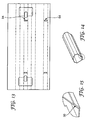
- tubular member an alternative preferred embodiment of tubular member is illustrated.
- the blank shown in Figure 13 has axial scores or cuts to form an octagonal tubular member, as shown in Figure 14.
- the tubular member is formed from corrugated polypropylene and secured by heat-welding overlapping portions, as illustrated in Figure 15.
- Figure 16 shows an alternative embodiment in which the tubular member 4 is provided with opposed pockets 54.
- a strengthening member 52 formed from a structural material, for example polypropylene, polyester or polyamide, is held in each pocket and the jaws 7, 9 are releasably secured to the strengthening members.
- Figure 17 illustrates an alternative embodiment in which the spacer 6 comprises a band of spring metal that surrounds the first end of each tubular member 4.
- the band and the tubular members lie flat when under a suitable applied load, but the band reverts to the illustrated rest position when the load is removed, causing at least the first end of the tubular members to open up sufficiently to receive a fork-lift tine.
- spacer 6 comprises a pair of elongate members 32 formed from spring metal and joined by fastening means 33, in this example a rivet.
- fastening means 33 in this example a rivet.
- the spring metal from which the spacer is formed provides the necessary spring means which bias the jaw members 7, 9 to the open position.
- FIG 19 A preferred embodiment of the invention is shown in Figure 19, which is similar to that of Figure 1 but with the following differences.
- the upper part of each end 62 of each tubular member 4 has a chamfered edge which is cut away to points underneath the strap-cover tab 12.
- the strap-cover tab 12 is held in place by an elastic loop 58 with toggles 60 at each end, like a large elastic treasury tag.
- the toggles 60 are axially pushed through holes in the tabs 12 and then turned to retain the loop 58 under the tab 12.
- the lifting straps 26 of a bulk bag are secured under the strap-cover tabs 12, and the tabs 12 are then secured in place by pulling the elastic straps 58 underneath the tubular members 4.
- the fork-lift operator On seeing the tabs 12 open, the fork-lift operator is alerted to a problem and can lower the tines 28 before damage is done to the tubular members 4. The operator can then re-engage the tabs 12 and elastic loops 58 before proceeding again.
- the loops 58 are elastic because they are formed from an elastic material.
- the loops 58 could alternatively be elastic by virtue of being formed from a spring material, for example one or more coil springs or other mechanical equivalents.
- each tubular member 4 has a lower lip 64 which projects beyond the upper part of the tubular member.
- This feature enables a fork-lift tine to engage initially with the tubular member from above. By doing this, a fork-lift operator does not initially need to engage both tines in the tubular members by driving forward, which may not be feasible if the device 2 is not sitting substantially horizontally. This may be the case when the device is mounted on a bag that is stacked on one or more other bags and is tilted from the horizontal.
- the lip 64 enables a fork-lift operator to bring the tines 28 down until one of them engages with a lip 64.
- the fork-lift operator will see that engagement has taken place because the end of the tubular member(s) will be displaced downwardly. If one tubular member 4 is above the other, the upper one will be engaged first and pushed down by the tine. As the tines continue to be lowered, the other tine will subsequently engage with the other lip 64 so that the operator can see that both lips 64 are engaged. The operator can then drive forwards so as to insert both tines 28 into both tubular members 4. The entire process can be a one-man operation.
- the invention provides an improved bulk bag, a support device for supporting lifting straps of a bulk bag to facilitate handling by a fork-lift, and a spacer for use in the bag or support device.
- the support device will lie flat when under load but will reliably raise the lifting straps when the load has been removed, even after a long period of time under load.
Landscapes
- Engineering & Computer Science (AREA)
- Mechanical Engineering (AREA)
- Structural Engineering (AREA)
- Transportation (AREA)
- Geology (AREA)
- Life Sciences & Earth Sciences (AREA)
- Civil Engineering (AREA)
- Bag Frames (AREA)
- Medicines Containing Plant Substances (AREA)
- Air Bags (AREA)
- Control And Other Processes For Unpacking Of Materials (AREA)
- Crystals, And After-Treatments Of Crystals (AREA)
- Auxiliary Apparatuses For Manual Packaging Operations (AREA)
- Fertilizing (AREA)
Claims (32)
- Sac à grande capacité pour le stockage et le transport des matériaux en vrac, comprenant :un panneau inférieur ;une pluralité de panneaux latéraux ;une paire d'éléments de guidage tubulaires repliables (4) sensiblement parallèles, chaque élément de guidage tubulaire (4) ayant une première extrémité et une seconde extrémité et étant fixé sur ou adjacent à la partie supérieure d'un panneau latéral ; etune pluralité de sangles de levage (26) ;chaque extrémité de chaque élément de guidage tubulaire (4) supportant une sangle de levage (26) et les éléments tubulaires (4) étant raccordés ensemble par un premier dispositif d'espacement (6) qui comprend au moins un élément allongé axialement rigide (32) ;caractérisé en ce que le premier dispositif d'espacement (6) est doté d'une paire de mâchoires (7, 9) à chaque extrémité, chaque paire de mâchoires (7, 9) comprenant un premier élément de mâchoire (7) et un second élément de mâchoire (9) et pouvant être réglée entre une position ouverte et une position fermée et sollicitée dans la position ouverte par des moyens de ressort (10) ;chaque paire de mâchoires (7, 9) étant raccordée à un élément tubulaire (4) au niveau de ou adjacent à sa première extrémité moyennant quoi lorsque les mâchoires sont dans la position fermée, elles amènent au moins la première extrémité de chaque élément tubulaire (4) à se trouver sensiblement à plat et lorsque les mâchoires sont dans la position ouverte, elles provoquent ou permettent au moins à la première extrémité de chacun des éléments tubulaires (4) d'adopter une forme qui est appropriée pour recevoir une dent (28) d'un chariot élévateur à fourche.
- Sac selon la revendication 1, dans lequel le dispositif d'espacement (6) comprend une paire d'éléments allongés rigides (32) raccordés ensemble par des moyens de ressort (10), chaque extrémité de l'un des éléments allongés (32) comprenant l'un desdits premiers éléments de mâchoire (7) et chaque extrémité de l'autre élément allongé (32) comprenant l'un desdits seconds éléments de mâchoire (9).
- Sac selon la revendication 2, dans lequel les éléments allongés (32) de chaque dispositif d'espacement (6) sont raccordés ensemble de manière articulée.
- Sac selon l'une quelconque des revendications précédentes, dans lequel chaque élément tubulaire (4) a une fente ou une partie découpée (8) adjacente à chaque extrémité pour recevoir une partie de l'une des sangles de levage (26) et est prévu avec une languette de recouvrement de sangle (12) pour chaque fente ou partie découpée (8), qui est raccordée de manière articulée le long de son bord.
- Sac selon la revendication 4, dans lequel chaque languette de recouvrement de sangle (12) est solidaire de l'élément tubulaire (4) et formée par découpe, et dans lequel chaque languette de recouvrement de sangle (12) est prévue avec une languette de blocage (14) qui est découpée à partir d'une région qui recouvre le raccordement d'articulation et laquelle languette de blocage peut être glissée au-dessous d'un bord libre de la partie découpée (8) pour retenir la languette de recouvrement de sangle (12) sur la partie découpée (8).
- Sac selon l'une quelconque des revendications précédentes, dans lequel les éléments de guidage tubulaires (4) sont raccordés ensemble au niveau de ou adjacents à leurs secondes extrémités par un second dispositif d'espacement (6).
- Sac selon la revendication 1, dans lequel chacune desdites sangles de levage (26) est intégrée avec l'un desdits éléments de guidage tubulaires (4).
- Sac selon l'une quelconque des revendications précédentes, dans lequel chacun desdits éléments tubulaires (4) est intégré avec un bord supérieur d'un panneau latéral.
- Sac selon l'une quelconque des revendications précédentes, dans lequel au moins ladite première extrémité de chaque élément tubulaire (4) est prévue avec une lèvre inférieure en saillie (64) qui, lorsqu'elle est utilisée, permet aux dents (28) d'un chariot élévateur à fourche de mettre en prise lesdites lèvres (64) en abaissant lesdites dents (28) depuis le dessus desdits éléments tubulaires (4).
- Dispositif de support (2) pour la fixation à un sac à grande capacité comprenant un panneau inférieur, une pluralité de panneaux latéraux et une pluralité de sangles de levage, le dispositif (2) comprenant une paire d'éléments de guidage tubulaires repliables (4) sensiblement parallèles, ayant chacun une première extrémité et une seconde extrémité et qui sont raccordés ensemble par un dispositif d'espacement (6) qui comprend au moins un élément allongé axialement rigide (32) ;
caractérisé en ce que le premier élément d'espacement (6) est prévu avec une paire de mâchoires (7, 9) à chaque extrémité, chaque paire de mâchoires comprenant un premier élément de mâchoire (7) et un second élément de mâchoire (9) et pouvant être réglable entre une position ouverte et une position fermée et sollicitée dans la position ouverte par des moyens de ressort (10) ;
chaque paire de mâchoires (7, 9) étant raccordée à un élément tubulaire (4) au niveau de ou adjacent à sa première extrémité moyennant quoi lorsque les mâchoires sont dans la position fermée, elles amènent au moins la première extrémité de chaque élément tubulaire (4) à se trouver sensiblement à plat et lorsque les mâchoires sont dans la position ouverte, elles provoquent ou permettent au moins à la première extrémité de chacun des éléments tubulaires (4) d'adopter une forme qui est appropriée pour recevoir une dent (28) d'un chariot élévateur à fourche. - Dispositif selon la revendication 10, dans lequel le premier dispositif d'espacement (6) comprend une paire d'éléments allongés rigides (32) raccordés ensemble par des moyens de ressort (10), chaque extrémité de l'un des éléments allongés (32) comprenant l'un desdits premiers éléments de mâchoire (7) et chaque extrémité de l'autre élément allongé (32) comprenant l'un desdits seconds éléments de mâchoire (9).
- Dispositif selon la revendication 11, dans lequel les éléments allongés (32) du premier dispositif d'espacement (6) sont raccordés ensemble de manière articulée.
- Dispositif selon la revendication 11 ou la revendication 12, dans lequel les éléments allongés (32) sont formés à partir d'une matière plastique ondulée.
- Dispositif selon l'une quelconque des revendications 10 à 12, dans lequel les moyens de ressort (10) comprennent au moins un ressort hélicoïdal.
- Dispositif selon la revendication 13, dans lequel les moyens de ressort (10) comprennent au moins un ressort hélicoïdal ayant des extrémités libres équipées d'ardillons (24) et dans lequel le ou chaque ressort (10) est raccordé entre les éléments allongés (32) par la mise en prise des ardillons (24) dans des canaux dans les éléments allongés (32).
- Dispositif selon l'une quelconque des revendications 10 à 15, dans lequel les éléments tubulaires (4) ont une section transversale hexagonale.
- Dispositif selon l'une quelconque des revendications 10 à 15, dans lequel les éléments tubulaires (4) ont une section transversale octogonale.
- Dispositif selon l'une quelconque des revendications 10 à 17, dans lequel les éléments tubulaires (4) sont formés à partir d'une matière plastique ondulée.
- Dispositif selon l'une quelconque des revendications 10 à 18, dans lequel les éléments tubulaires (4) peuvent être fixés sur les panneaux latéraux d'un sac à grande capacité au moyen des sangles de levage (26).
- Dispositif selon la revendication 19, dans lequel chaque élément tubulaire (4) a une fente ou partie découpée (8) adjacente aux première et seconde extrémités pour recevoir une partie d'une sangle de levage (26) d'un sac à grande capacité et est prévu avec une languette de recouvrement de sangle (12) pour chaque fente ou partie découpée (8) qui est raccordée de manière articulée le long de son bord.
- Dispositif selon la revendication 20, dans lequel chaque languette de recouvrement de sangle (12) est solidaire de l'élément tubulaire (4) et formée par découpe, et dans lequel chaque languette de recouvrement de sangle (12) est équipée d'une languette de blocage (14) qui est découpée à partir d'une région qui recouvre le raccordement d'articulation et laquelle languette de blocage (14) peut être glissée au-dessous d'un bord libre de la partie découpée (8) pour retenir la languette de recouvrement de sangle (12) sur la partie découpée (8).
- Dispositif selon l'une quelconque des revendications 10 à 21, dans lequel les éléments de guidage tubulaires (4) sont raccordés ensemble au niveau de ou adjacents à leurs secondes extrémités par un second dispositif d'espacement (6).
- Dispositif selon l'une quelconque des revendications 10 à 22, dans lequel chaque élément tubulaire (4) comprend un tube externe (4b) et un tube interne (4a) qui sont raccordés ensemble, le premier dispositif d'espacement (6) étant raccordé à au moins l'un parmi le tube interne et le tube externe de chaque élément de guidage.
- Dispositif selon la revendication 23, dans lequel une seule fixation (42, 46) raccorde de manière amovible un élément de mâchoire (7) du premier dispositif d'espacement (6) conjointement au tube interne (4a) et au tube externe (4b).
- Dispositif selon la revendication 19, dans lequel au moins l'élément tubulaire (4) a une fente ou partie découpée (8) adjacente à au moins l'une desdites première et seconde extrémités pour recevoir une partie d'une sangle de levage (26) d'un sac à grande capacité et est prévu avec un languette de recouvrement de sangle (12) pour ladite fente ou partie découpée (8), qui est raccordée de manière articulée le long de son bord ;
dans lequel ladite languette de recouvrement de sangle (12) est prévue avec une boucle élastique (58) pour maintenir en place ladite languette (12) de manière amovible lorsque ladite boucle élastique (58) est disposée autour dudit élément tubulaire (4) ; et
dans lequel ledit élément tubulaire (4) a une partie chanfreinée ou progressivement rétrécie (62) s'étendant vers le haut à l'usage à partir de ladite extrémité vers ladite fente ou partie découpée (8). - Dispositif selon la revendication 10, dans lequel au moins ladite première extrémité de chaque élément tubulaire (4) est prévue avec une lèvre inférieure en saillie (64) qui, lorsqu'elle est utilisée, permet aux dents (28) d'un chariot élévateur à fourche de se mettre en prise avec lesdites lèvres (64) en abaissant lesdites dents depuis le dessus desdits éléments tubulaires (4).
- Dispositif d'espacement (6) pour la fixation entre des éléments de guidage tubulaires (4) sensiblement parallèles sur les bords supérieurs opposés d'un sac à grande capacité, approprié pour être utilisé dans un sac selon la revendication 1 ou un dispositif selon la revendication 10, le dispositif d'espacement comprenant une paire d'éléments allongés axialement rigides (32) raccordés ensemble par des moyens de ressort (10) et étant prévu avec une paire de mâchoires (7, 9) à chaque extrémité ; chaque paire de mâchoires comprenant un premier élément de mâchoire (7) et un second élément de mâchoire (9) et étant réglable entre une position ouverte et une position fermée et sollicitée dans la position ouverte par les moyens de ressort (10), chaque extrémité de l'un des éléments allongés (32) comprenant l'un desdits premiers éléments de mâchoire (7) et chaque extrémité de l'autre élément allongé (32) comprenant l'un desdits seconds éléments de mâchoire (9) ;
caractérisé en ce que les moyens de ressort (10) permettent de replier à plat le dispositif d'espacement (6) lorsqu'il est sous une charge, de sorte que les éléments allongés (32) se trouvent les uns au-dessus des autres, mais les moyens de ressort (10) poussent les éléments allongés (32) à distance lorsque le dispositif d'espacement (6) est plat et ramènent le dispositif d'espacement (6) à une configuration de repos dans laquelle les extrémités libres des éléments allongés (32) sont éloignées lorsque la charge est retirée. - Dispositif d'espacement (6) selon la revendication 27, dans lequel les éléments allongés (32) sont raccordés ensemble de manière articulée.
- Dispositif d'espacement (6) selon la revendication 27 ou la revendication 28, dans lequel les éléments allongés (32) sont formés à partir d'une matière plastique ondulée.
- Dispositif d'espacement (6) selon l'une quelconque des revendications 27 à 29, dans lequel les moyens de ressort (10) comprennent au moins un ressort hélicoïdal.
- Dispositif d'espacement (6) selon la revendication 29, dans lequel les moyens de ressort (10) comprennent au moins un ressort hélicoïdal ayant des extrémités libres dotées d'ardillons (24) et dans lequel le ou chaque ressort est raccordé entre les éléments allongés (32) par la mise en prise des ardillons (24) dans les canaux dans les éléments allongés (32).
- Dispositif de support (2) pour la fixation à un sac à grande capacité, le dispositif comprenant une paire d'éléments de guidage tubulaires repliables (4) sensiblement parallèles qui sont raccordés ensemble au niveau de ou adjacents à chaque extrémité par des dispositifs d'espacement (6) ;
caractérisé en ce que chaque dispositif d'espacement (6) comprend une paire d'éléments allongés rigides (32) raccordés ensemble par des moyens de ressort (10) ;
chaque élément allongé (32) de chaque dispositif d'espacement (6) étant raccordé à chaque élément tubulaire (4) au niveau d'un emplacement différent de celui auquel l'autre élément allongé (32) est raccordé ;
moyennant quoi le dispositif de support (2) est à plat lorsqu'il est sous une charge appropriée mais les moyens de ressort (10) provoquent l'éloignement des éléments allongés (32) de chaque dispositif d'espacement (6) l'un de l'autre lorsque la charge est retirée, amenant ainsi les éléments tubulaires (6) à adopter une forme qui est appropriée pour recevoir et guider les dents (28) d'un chariot élévateur à fourche.
Applications Claiming Priority (5)
| Application Number | Priority Date | Filing Date | Title |
|---|---|---|---|
| GB0225235A GB0225235D0 (en) | 2002-10-30 | 2002-10-30 | Support Device |
| GB0225235 | 2002-10-30 | ||
| GB0307769 | 2003-04-04 | ||
| GB0307769A GB2396146B (en) | 2002-10-30 | 2003-04-04 | Bulk bags |
| PCT/GB2003/004698 WO2004039718A1 (fr) | 2002-10-30 | 2003-10-29 | Sacs grande capacite |
Publications (2)
| Publication Number | Publication Date |
|---|---|
| EP1556305A1 EP1556305A1 (fr) | 2005-07-27 |
| EP1556305B1 true EP1556305B1 (fr) | 2007-05-09 |
Family
ID=32232394
Family Applications (1)
| Application Number | Title | Priority Date | Filing Date |
|---|---|---|---|
| EP03809790A Expired - Lifetime EP1556305B1 (fr) | 2002-10-30 | 2003-10-29 | Sacs grande capacite |
Country Status (7)
| Country | Link |
|---|---|
| US (1) | US7226209B2 (fr) |
| EP (1) | EP1556305B1 (fr) |
| AT (1) | ATE361894T1 (fr) |
| AU (1) | AU2003276429B2 (fr) |
| CA (1) | CA2504360A1 (fr) |
| DE (1) | DE60313788T2 (fr) |
| WO (1) | WO2004039718A1 (fr) |
Cited By (1)
| Publication number | Priority date | Publication date | Assignee | Title |
|---|---|---|---|---|
| CN101531267B (zh) * | 2009-04-23 | 2012-12-05 | 周超 | 用于搬运多个袋装物的方法 |
Families Citing this family (4)
| Publication number | Priority date | Publication date | Assignee | Title |
|---|---|---|---|---|
| US8322924B2 (en) * | 2008-11-06 | 2012-12-04 | Robert Noble | Trash collection and removal system |
| EP2785616B1 (fr) * | 2011-11-28 | 2019-07-03 | Blue Ocean Containers B.V. | Système comprenant un récipient dit "big bag", un support et une corde |
| US11186470B2 (en) * | 2018-03-30 | 2021-11-30 | Deloren E. Anderson | Multi-tine lifting implement |
| US11148919B1 (en) * | 2020-02-27 | 2021-10-19 | Timothy Lane Middleton | Method and apparatus for lifting heavy load |
Family Cites Families (31)
| Publication number | Priority date | Publication date | Assignee | Title |
|---|---|---|---|---|
| GB210647A (en) | 1923-03-06 | 1924-02-07 | Ernest Charles Baldwin | Improvements in and relating to devices for stopping leaks in pipes and the like |
| US1512053A (en) | 1923-05-29 | 1924-10-21 | Ridlinghafer Charles | Market-bag carrier |
| GB340466A (en) | 1930-05-26 | 1931-01-01 | Crampton Brothers Ltd | Improvements in or relating to plumbers' pipe cramps |
| US3131832A (en) * | 1963-02-15 | 1964-05-05 | Strandberg Arne | Collapsible container and support therefor |
| US3282621A (en) | 1963-12-26 | 1966-11-01 | Thomas G Peterson | Combination lifting pallet and collapsible storage and shipping container |
| FR2229574B1 (fr) | 1973-05-17 | 1977-01-07 | Burel Sa Ets F | |
| FR2306134A1 (fr) | 1975-04-02 | 1976-10-29 | Pedelucq Jean Michel | Perfectionnements aux conteneurs |
| DE7607644U1 (de) | 1976-03-12 | 1976-07-22 | Krause Walter | Transportbehaelter aus biegeschlaffem Material |
| US4271883A (en) * | 1978-03-10 | 1981-06-09 | Walter Krause | Storage arrangement |
| US4759473A (en) | 1979-06-08 | 1988-07-26 | Super Sack Manufacturing Corporation | Collapsible receptacle with integral sling |
| GB2050298B (en) | 1979-06-08 | 1984-04-04 | Super Sack Mfg Corp | Collapsible receptable with integral sling |
| US4300608A (en) | 1980-05-07 | 1981-11-17 | Bonar Industries Inc. | Self-raising strap loop |
| DK147881C (da) | 1981-02-13 | 1985-07-15 | Nyborg Plast | Saek til rislegods og fremgangsmaade til fremstilling af denne |
| GB2097755A (en) | 1981-05-01 | 1982-11-10 | Mulox Ibc Ltd | Container bag |
| US4457456A (en) | 1981-12-31 | 1984-07-03 | Super Sack Manufacturing Company | Collapsible receptacle with static electric charge elimination |
| US4499599A (en) | 1983-01-03 | 1985-02-12 | Polett Walter J | Stackable flexible bulk container |
| US4597749A (en) | 1984-01-16 | 1986-07-01 | Mobil Oil Corporation | Thermoplastic bag having reinforced handles and method of manufacture |
| USH37H (en) * | 1985-06-03 | 1986-03-04 | Polaroid Corporation | Film pack having improved pack spring |
| FR2603259B1 (fr) * | 1986-09-03 | 1989-06-30 | Mecaroute Sa | Dispositif pour faciliter la manutention de sacs de grande capacite, remplis de materiaux pulverulents ou granules |
| GB8925870D0 (en) * | 1989-11-15 | 1990-01-04 | Jaguar Cars | Belt drives |
| DE9404642U1 (de) * | 1994-03-18 | 1994-05-19 | Friedrich Knapp GmbH, 85591 Vaterstetten | Verbindungselement |
| US5542767A (en) * | 1994-05-24 | 1996-08-06 | Barclay Brown | Bag stuffer |
| FR2721304B1 (fr) | 1994-06-16 | 1996-08-30 | Mecaroute | Dispositif de manutention et ensemble de manutention incorporant ledit dispositif. |
| AUPN910996A0 (en) | 1996-04-03 | 1996-05-02 | Southcorp Australia Pty Ltd | Lifting device for bulk type bags |
| US5607237A (en) | 1996-04-09 | 1997-03-04 | Custom Packaging Systems, Inc. | Bulk bag with lift straps |
| US5924796A (en) | 1997-02-06 | 1999-07-20 | Super Sack Manufacturing Corp. | One piece flexible intermediate bulk container and process for manufacturing same |
| US5865540A (en) | 1997-02-06 | 1999-02-02 | Super Sack Mfg. Corp. | One piece flexible intermediate bulk container and process for manufacturing same |
| US5864540A (en) * | 1997-04-04 | 1999-01-26 | At&T Corp/Csi Zeinet(A Cabletron Co.) | Method for integrated traffic shaping in a packet-switched network |
| CA2205273A1 (fr) | 1997-05-13 | 1998-11-13 | William Shackleton | Sangle de levage demeurant droit pour recipient de matiere en vrac |
| GB2333091A (en) | 1998-01-07 | 1999-07-14 | Mark Jardine | Bulk bag with tubular lifting members |
| DE29905662U1 (de) * | 1999-03-26 | 2000-08-10 | Patent-Treuhand-Gesellschaft für elektrische Glühlampen mbH, 81543 München | Metallhalogenid-Entladungslampe mit langer Lebensdauer |
-
2003
- 2003-10-28 US US10/695,638 patent/US7226209B2/en not_active Expired - Fee Related
- 2003-10-29 EP EP03809790A patent/EP1556305B1/fr not_active Expired - Lifetime
- 2003-10-29 AT AT03809790T patent/ATE361894T1/de not_active IP Right Cessation
- 2003-10-29 AU AU2003276429A patent/AU2003276429B2/en not_active Expired - Fee Related
- 2003-10-29 CA CA002504360A patent/CA2504360A1/fr not_active Abandoned
- 2003-10-29 WO PCT/GB2003/004698 patent/WO2004039718A1/fr not_active Ceased
- 2003-10-29 DE DE60313788T patent/DE60313788T2/de not_active Expired - Fee Related
Non-Patent Citations (1)
| Title |
|---|
| None * |
Cited By (1)
| Publication number | Priority date | Publication date | Assignee | Title |
|---|---|---|---|---|
| CN101531267B (zh) * | 2009-04-23 | 2012-12-05 | 周超 | 用于搬运多个袋装物的方法 |
Also Published As
| Publication number | Publication date |
|---|---|
| ATE361894T1 (de) | 2007-06-15 |
| AU2003276429B2 (en) | 2008-03-20 |
| AU2003276429A1 (en) | 2004-05-25 |
| DE60313788T2 (de) | 2008-01-24 |
| DE60313788D1 (de) | 2007-06-21 |
| US20040120608A1 (en) | 2004-06-24 |
| EP1556305A1 (fr) | 2005-07-27 |
| WO2004039718A1 (fr) | 2004-05-13 |
| US7226209B2 (en) | 2007-06-05 |
| CA2504360A1 (fr) | 2004-05-13 |
Similar Documents
| Publication | Publication Date | Title |
|---|---|---|
| US6467625B2 (en) | Bulk bag | |
| US4499599A (en) | Stackable flexible bulk container | |
| US6935500B1 (en) | Bulk bag with support system | |
| EP1045802B1 (fr) | Sac | |
| US8365912B2 (en) | Wire containment structure including container and bag | |
| CA2766264C (fr) | Recipient flexible de materiaux en vrac et sa structure de support amovible | |
| CA1198990A (fr) | Conteneur pour materiau en vrac | |
| US5492270A (en) | Shipping container | |
| JPH04239469A (ja) | サスペンションパッケージ | |
| WO2013070516A1 (fr) | Contenant de type sac de silo | |
| US4395067A (en) | Lifting assembly | |
| EP1556305B1 (fr) | Sacs grande capacite | |
| WO2015031951A1 (fr) | Sac de manipulation de matériaux, système de sac et procédé de manipulation de matériaux au moyen d'un sac ou système de sac | |
| EP2036826A2 (fr) | Palette dotée d'un cadre et d'un sac pliables | |
| JPH0624487A (ja) | バラ荷材料、流体および同等品用コンテナー | |
| GB2396146A (en) | Supports for bulk bags | |
| US20030230691A1 (en) | Apparatus and method for facilitating supporting of an object | |
| US20210053752A1 (en) | Shipping bag | |
| CA1279630C (fr) | Recipient pour sac a ordures a remplir et comprimer | |
| GB2094756A (en) | Bulk containers | |
| JPH0516620U (ja) | 梱包装置 | |
| GB2043034A (en) | Palletisation of fibre-board packing cases | |
| JPH0872980A (ja) | 可撓伸縮コンテナ |
Legal Events
| Date | Code | Title | Description |
|---|---|---|---|
| PUAI | Public reference made under article 153(3) epc to a published international application that has entered the european phase |
Free format text: ORIGINAL CODE: 0009012 |
|
| 17P | Request for examination filed |
Effective date: 20050423 |
|
| AK | Designated contracting states |
Kind code of ref document: A1 Designated state(s): AT BE BG CH CY CZ DE DK EE ES FI FR GB GR HU IE IT LI LU MC NL PT RO SE SI SK TR |
|
| AX | Request for extension of the european patent |
Extension state: AL LT LV MK |
|
| DAX | Request for extension of the european patent (deleted) | ||
| GRAP | Despatch of communication of intention to grant a patent |
Free format text: ORIGINAL CODE: EPIDOSNIGR1 |
|
| GRAS | Grant fee paid |
Free format text: ORIGINAL CODE: EPIDOSNIGR3 |
|
| GRAA | (expected) grant |
Free format text: ORIGINAL CODE: 0009210 |
|
| RBV | Designated contracting states (corrected) |
Designated state(s): AT BE BG CH CY CZ DE DK EE ES FI FR GR HU IE IT LI LU MC NL PT RO SE SI SK TR |
|
| AK | Designated contracting states |
Kind code of ref document: B1 Designated state(s): AT BE BG CH CY CZ DE DK EE ES FI FR GR HU IE IT LI LU MC NL PT RO SE SI SK TR |
|
| PG25 | Lapsed in a contracting state [announced via postgrant information from national office to epo] |
Ref country code: LI Free format text: LAPSE BECAUSE OF FAILURE TO SUBMIT A TRANSLATION OF THE DESCRIPTION OR TO PAY THE FEE WITHIN THE PRESCRIBED TIME-LIMIT Effective date: 20070509 Ref country code: CH Free format text: LAPSE BECAUSE OF FAILURE TO SUBMIT A TRANSLATION OF THE DESCRIPTION OR TO PAY THE FEE WITHIN THE PRESCRIBED TIME-LIMIT Effective date: 20070509 Ref country code: FI Free format text: LAPSE BECAUSE OF FAILURE TO SUBMIT A TRANSLATION OF THE DESCRIPTION OR TO PAY THE FEE WITHIN THE PRESCRIBED TIME-LIMIT Effective date: 20070509 |
|
| RBV | Designated contracting states (corrected) |
Designated state(s): AT BE BG CH CY CZ DE DK EE ES FI FR GR HU IE IT LI LU MC NL PT RO SE SI SK TR |
|
| REG | Reference to a national code |
Ref country code: CH Ref legal event code: EP |
|
| REG | Reference to a national code |
Ref country code: IE Ref legal event code: FG4D |
|
| REF | Corresponds to: |
Ref document number: 60313788 Country of ref document: DE Date of ref document: 20070621 Kind code of ref document: P |
|
| PG25 | Lapsed in a contracting state [announced via postgrant information from national office to epo] |
Ref country code: ES Free format text: LAPSE BECAUSE OF FAILURE TO SUBMIT A TRANSLATION OF THE DESCRIPTION OR TO PAY THE FEE WITHIN THE PRESCRIBED TIME-LIMIT Effective date: 20070820 |
|
| REG | Reference to a national code |
Ref country code: SE Ref legal event code: TRGR |
|
| NLV1 | Nl: lapsed or annulled due to failure to fulfill the requirements of art. 29p and 29m of the patents act | ||
| ET | Fr: translation filed | ||
| REG | Reference to a national code |
Ref country code: CH Ref legal event code: PL |
|
| PG25 | Lapsed in a contracting state [announced via postgrant information from national office to epo] |
Ref country code: AT Free format text: LAPSE BECAUSE OF FAILURE TO SUBMIT A TRANSLATION OF THE DESCRIPTION OR TO PAY THE FEE WITHIN THE PRESCRIBED TIME-LIMIT Effective date: 20070509 |
|
| PG25 | Lapsed in a contracting state [announced via postgrant information from national office to epo] |
Ref country code: BE Free format text: LAPSE BECAUSE OF FAILURE TO SUBMIT A TRANSLATION OF THE DESCRIPTION OR TO PAY THE FEE WITHIN THE PRESCRIBED TIME-LIMIT Effective date: 20070509 |
|
| PG25 | Lapsed in a contracting state [announced via postgrant information from national office to epo] |
Ref country code: DK Free format text: LAPSE BECAUSE OF FAILURE TO SUBMIT A TRANSLATION OF THE DESCRIPTION OR TO PAY THE FEE WITHIN THE PRESCRIBED TIME-LIMIT Effective date: 20070509 Ref country code: SI Free format text: LAPSE BECAUSE OF FAILURE TO SUBMIT A TRANSLATION OF THE DESCRIPTION OR TO PAY THE FEE WITHIN THE PRESCRIBED TIME-LIMIT Effective date: 20070509 Ref country code: NL Free format text: LAPSE BECAUSE OF FAILURE TO SUBMIT A TRANSLATION OF THE DESCRIPTION OR TO PAY THE FEE WITHIN THE PRESCRIBED TIME-LIMIT Effective date: 20070509 Ref country code: PT Free format text: LAPSE BECAUSE OF FAILURE TO SUBMIT A TRANSLATION OF THE DESCRIPTION OR TO PAY THE FEE WITHIN THE PRESCRIBED TIME-LIMIT Effective date: 20071009 Ref country code: CZ Free format text: LAPSE BECAUSE OF FAILURE TO SUBMIT A TRANSLATION OF THE DESCRIPTION OR TO PAY THE FEE WITHIN THE PRESCRIBED TIME-LIMIT Effective date: 20070509 Ref country code: BG Free format text: LAPSE BECAUSE OF FAILURE TO SUBMIT A TRANSLATION OF THE DESCRIPTION OR TO PAY THE FEE WITHIN THE PRESCRIBED TIME-LIMIT Effective date: 20070809 |
|
| PGFP | Annual fee paid to national office [announced via postgrant information from national office to epo] |
Ref country code: DE Payment date: 20070807 Year of fee payment: 5 Ref country code: SE Payment date: 20070726 Year of fee payment: 5 |
|
| PG25 | Lapsed in a contracting state [announced via postgrant information from national office to epo] |
Ref country code: SK Free format text: LAPSE BECAUSE OF FAILURE TO SUBMIT A TRANSLATION OF THE DESCRIPTION OR TO PAY THE FEE WITHIN THE PRESCRIBED TIME-LIMIT Effective date: 20070509 |
|
| PLBE | No opposition filed within time limit |
Free format text: ORIGINAL CODE: 0009261 |
|
| STAA | Information on the status of an ep patent application or granted ep patent |
Free format text: STATUS: NO OPPOSITION FILED WITHIN TIME LIMIT |
|
| 26N | No opposition filed |
Effective date: 20080212 |
|
| PG25 | Lapsed in a contracting state [announced via postgrant information from national office to epo] |
Ref country code: IT Free format text: LAPSE BECAUSE OF FAILURE TO SUBMIT A TRANSLATION OF THE DESCRIPTION OR TO PAY THE FEE WITHIN THE PRESCRIBED TIME-LIMIT Effective date: 20070509 Ref country code: GR Free format text: LAPSE BECAUSE OF FAILURE TO SUBMIT A TRANSLATION OF THE DESCRIPTION OR TO PAY THE FEE WITHIN THE PRESCRIBED TIME-LIMIT Effective date: 20070810 |
|
| PGFP | Annual fee paid to national office [announced via postgrant information from national office to epo] |
Ref country code: FR Payment date: 20070824 Year of fee payment: 5 |
|
| PG25 | Lapsed in a contracting state [announced via postgrant information from national office to epo] |
Ref country code: MC Free format text: LAPSE BECAUSE OF NON-PAYMENT OF DUE FEES Effective date: 20071031 Ref country code: RO Free format text: LAPSE BECAUSE OF FAILURE TO SUBMIT A TRANSLATION OF THE DESCRIPTION OR TO PAY THE FEE WITHIN THE PRESCRIBED TIME-LIMIT Effective date: 20070509 |
|
| PG25 | Lapsed in a contracting state [announced via postgrant information from national office to epo] |
Ref country code: IE Free format text: LAPSE BECAUSE OF NON-PAYMENT OF DUE FEES Effective date: 20071030 |
|
| PG25 | Lapsed in a contracting state [announced via postgrant information from national office to epo] |
Ref country code: EE Free format text: LAPSE BECAUSE OF FAILURE TO SUBMIT A TRANSLATION OF THE DESCRIPTION OR TO PAY THE FEE WITHIN THE PRESCRIBED TIME-LIMIT Effective date: 20070509 |
|
| EUG | Se: european patent has lapsed | ||
| REG | Reference to a national code |
Ref country code: FR Ref legal event code: ST Effective date: 20090630 |
|
| PG25 | Lapsed in a contracting state [announced via postgrant information from national office to epo] |
Ref country code: CY Free format text: LAPSE BECAUSE OF FAILURE TO SUBMIT A TRANSLATION OF THE DESCRIPTION OR TO PAY THE FEE WITHIN THE PRESCRIBED TIME-LIMIT Effective date: 20070509 |
|
| PG25 | Lapsed in a contracting state [announced via postgrant information from national office to epo] |
Ref country code: LU Free format text: LAPSE BECAUSE OF NON-PAYMENT OF DUE FEES Effective date: 20071029 Ref country code: DE Free format text: LAPSE BECAUSE OF NON-PAYMENT OF DUE FEES Effective date: 20090501 |
|
| PG25 | Lapsed in a contracting state [announced via postgrant information from national office to epo] |
Ref country code: TR Free format text: LAPSE BECAUSE OF FAILURE TO SUBMIT A TRANSLATION OF THE DESCRIPTION OR TO PAY THE FEE WITHIN THE PRESCRIBED TIME-LIMIT Effective date: 20070509 Ref country code: HU Free format text: LAPSE BECAUSE OF FAILURE TO SUBMIT A TRANSLATION OF THE DESCRIPTION OR TO PAY THE FEE WITHIN THE PRESCRIBED TIME-LIMIT Effective date: 20071110 |
|
| PG25 | Lapsed in a contracting state [announced via postgrant information from national office to epo] |
Ref country code: FR Free format text: LAPSE BECAUSE OF NON-PAYMENT OF DUE FEES Effective date: 20081031 |
|
| PG25 | Lapsed in a contracting state [announced via postgrant information from national office to epo] |
Ref country code: SE Free format text: LAPSE BECAUSE OF NON-PAYMENT OF DUE FEES Effective date: 20081030 |