EP1555928B1 - Medical device sheath apparatus and method of making the same - Google Patents
Medical device sheath apparatus and method of making the same Download PDFInfo
- Publication number
- EP1555928B1 EP1555928B1 EP03777606A EP03777606A EP1555928B1 EP 1555928 B1 EP1555928 B1 EP 1555928B1 EP 03777606 A EP03777606 A EP 03777606A EP 03777606 A EP03777606 A EP 03777606A EP 1555928 B1 EP1555928 B1 EP 1555928B1
- Authority
- EP
- European Patent Office
- Prior art keywords
- sheath
- medical device
- seal
- housing
- dilator
- Prior art date
- Legal status (The legal status is an assumption and is not a legal conclusion. Google has not performed a legal analysis and makes no representation as to the accuracy of the status listed.)
- Expired - Lifetime
Links
- 238000004519 manufacturing process Methods 0.000 title claims description 5
- 238000011282 treatment Methods 0.000 claims abstract description 37
- 238000000034 method Methods 0.000 claims abstract description 17
- 238000007789 sealing Methods 0.000 claims abstract description 6
- 230000001225 therapeutic effect Effects 0.000 claims abstract description 5
- 230000005670 electromagnetic radiation Effects 0.000 claims abstract description 4
- XLYOFNOQVPJJNP-UHFFFAOYSA-N water Substances O XLYOFNOQVPJJNP-UHFFFAOYSA-N 0.000 claims description 38
- 238000000576 coating method Methods 0.000 claims description 12
- 239000000835 fiber Substances 0.000 claims description 12
- 238000003780 insertion Methods 0.000 claims description 12
- 230000037431 insertion Effects 0.000 claims description 12
- 239000011248 coating agent Substances 0.000 claims description 10
- 239000000463 material Substances 0.000 claims description 8
- 239000013536 elastomeric material Substances 0.000 claims description 5
- 230000013011 mating Effects 0.000 claims description 5
- 239000013307 optical fiber Substances 0.000 claims description 4
- BQCADISMDOOEFD-UHFFFAOYSA-N Silver Chemical compound [Ag] BQCADISMDOOEFD-UHFFFAOYSA-N 0.000 claims description 3
- GWEVSGVZZGPLCZ-UHFFFAOYSA-N Titan oxide Chemical compound O=[Ti]=O GWEVSGVZZGPLCZ-UHFFFAOYSA-N 0.000 claims description 3
- 229910052782 aluminium Inorganic materials 0.000 claims description 3
- XAGFODPZIPBFFR-UHFFFAOYSA-N aluminium Chemical compound [Al] XAGFODPZIPBFFR-UHFFFAOYSA-N 0.000 claims description 3
- 239000006229 carbon black Substances 0.000 claims description 3
- 230000000916 dilatatory effect Effects 0.000 claims description 3
- PCHJSUWPFVWCPO-UHFFFAOYSA-N gold Chemical compound [Au] PCHJSUWPFVWCPO-UHFFFAOYSA-N 0.000 claims description 3
- 229910052737 gold Inorganic materials 0.000 claims description 3
- 239000010931 gold Substances 0.000 claims description 3
- 229910052709 silver Inorganic materials 0.000 claims description 3
- 239000004332 silver Substances 0.000 claims description 3
- OGIDPMRJRNCKJF-UHFFFAOYSA-N titanium oxide Inorganic materials [Ti]=O OGIDPMRJRNCKJF-UHFFFAOYSA-N 0.000 claims description 3
- 238000002604 ultrasonography Methods 0.000 claims description 3
- 230000008878 coupling Effects 0.000 claims 5
- 238000010168 coupling process Methods 0.000 claims 5
- 238000005859 coupling reaction Methods 0.000 claims 5
- 230000001678 irradiating effect Effects 0.000 claims 5
- 239000012620 biological material Substances 0.000 claims 4
- 239000006117 anti-reflective coating Substances 0.000 claims 2
- 239000012530 fluid Substances 0.000 description 11
- 210000003238 esophagus Anatomy 0.000 description 10
- 210000000056 organ Anatomy 0.000 description 9
- 239000003504 photosensitizing agent Substances 0.000 description 6
- 230000005855 radiation Effects 0.000 description 6
- 210000003932 urinary bladder Anatomy 0.000 description 6
- 230000008901 benefit Effects 0.000 description 4
- 210000001072 colon Anatomy 0.000 description 4
- 239000007788 liquid Substances 0.000 description 4
- 238000012800 visualization Methods 0.000 description 4
- 201000010099 disease Diseases 0.000 description 3
- 208000037265 diseases, disorders, signs and symptoms Diseases 0.000 description 3
- 238000002560 therapeutic procedure Methods 0.000 description 3
- ZGXJTSGNIOSYLO-UHFFFAOYSA-N 88755TAZ87 Chemical compound NCC(=O)CCC(O)=O ZGXJTSGNIOSYLO-UHFFFAOYSA-N 0.000 description 2
- 208000023514 Barrett esophagus Diseases 0.000 description 2
- 208000023665 Barrett oesophagus Diseases 0.000 description 2
- 208000031481 Pathologic Constriction Diseases 0.000 description 2
- NIXOWILDQLNWCW-UHFFFAOYSA-N acrylic acid group Chemical group C(C=C)(=O)O NIXOWILDQLNWCW-UHFFFAOYSA-N 0.000 description 2
- 230000003213 activating effect Effects 0.000 description 2
- 230000004913 activation Effects 0.000 description 2
- 229960002749 aminolevulinic acid Drugs 0.000 description 2
- 210000000748 cardiovascular system Anatomy 0.000 description 2
- 230000000694 effects Effects 0.000 description 2
- 238000012986 modification Methods 0.000 description 2
- 230000004048 modification Effects 0.000 description 2
- 238000002428 photodynamic therapy Methods 0.000 description 2
- 229920000052 poly(p-xylylene) Polymers 0.000 description 2
- 229920000139 polyethylene terephthalate Polymers 0.000 description 2
- 239000005020 polyethylene terephthalate Substances 0.000 description 2
- 229920001296 polysiloxane Polymers 0.000 description 2
- 239000002243 precursor Substances 0.000 description 2
- 230000000007 visual effect Effects 0.000 description 2
- 206010005003 Bladder cancer Diseases 0.000 description 1
- 206010009944 Colon cancer Diseases 0.000 description 1
- RYECOJGRJDOGPP-UHFFFAOYSA-N Ethylurea Chemical compound CCNC(N)=O RYECOJGRJDOGPP-UHFFFAOYSA-N 0.000 description 1
- 229920002614 Polyether block amide Polymers 0.000 description 1
- -1 Polyethylene Terephthalate Polymers 0.000 description 1
- FAPWRFPIFSIZLT-UHFFFAOYSA-M Sodium chloride Chemical compound [Na+].[Cl-] FAPWRFPIFSIZLT-UHFFFAOYSA-M 0.000 description 1
- 208000007097 Urinary Bladder Neoplasms Diseases 0.000 description 1
- 210000001367 artery Anatomy 0.000 description 1
- 210000003445 biliary tract Anatomy 0.000 description 1
- 238000001574 biopsy Methods 0.000 description 1
- 238000006243 chemical reaction Methods 0.000 description 1
- 208000029742 colonic neoplasm Diseases 0.000 description 1
- 230000007423 decrease Effects 0.000 description 1
- 238000003745 diagnosis Methods 0.000 description 1
- 230000010339 dilation Effects 0.000 description 1
- 239000003814 drug Substances 0.000 description 1
- 210000001198 duodenum Anatomy 0.000 description 1
- 238000007667 floating Methods 0.000 description 1
- 230000002496 gastric effect Effects 0.000 description 1
- 210000005095 gastrointestinal system Anatomy 0.000 description 1
- 210000001035 gastrointestinal tract Anatomy 0.000 description 1
- 230000002631 hypothermal effect Effects 0.000 description 1
- 238000005286 illumination Methods 0.000 description 1
- 238000001746 injection moulding Methods 0.000 description 1
- 210000000936 intestine Anatomy 0.000 description 1
- 230000007246 mechanism Effects 0.000 description 1
- 229910052751 metal Inorganic materials 0.000 description 1
- 239000002184 metal Substances 0.000 description 1
- 150000002739 metals Chemical class 0.000 description 1
- 238000000465 moulding Methods 0.000 description 1
- 230000003287 optical effect Effects 0.000 description 1
- 244000052769 pathogen Species 0.000 description 1
- 230000001717 pathogenic effect Effects 0.000 description 1
- 208000017983 photosensitivity disease Diseases 0.000 description 1
- 231100000434 photosensitization Toxicity 0.000 description 1
- 230000000704 physical effect Effects 0.000 description 1
- 239000004033 plastic Substances 0.000 description 1
- 229920003023 plastic Polymers 0.000 description 1
- 239000011148 porous material Substances 0.000 description 1
- 230000008569 process Effects 0.000 description 1
- 238000005086 pumping Methods 0.000 description 1
- 210000001187 pylorus Anatomy 0.000 description 1
- 239000000523 sample Substances 0.000 description 1
- 239000011780 sodium chloride Substances 0.000 description 1
- 238000001228 spectrum Methods 0.000 description 1
- 210000005070 sphincter Anatomy 0.000 description 1
- 239000007921 spray Substances 0.000 description 1
- 210000002784 stomach Anatomy 0.000 description 1
- 238000001356 surgical procedure Methods 0.000 description 1
- 229920001169 thermoplastic Polymers 0.000 description 1
- 239000004416 thermosoftening plastic Substances 0.000 description 1
- 238000012546 transfer Methods 0.000 description 1
- 230000007704 transition Effects 0.000 description 1
- 201000005112 urinary bladder cancer Diseases 0.000 description 1
- 210000004291 uterus Anatomy 0.000 description 1
Images


Classifications
-
- A—HUMAN NECESSITIES
- A61—MEDICAL OR VETERINARY SCIENCE; HYGIENE
- A61B—DIAGNOSIS; SURGERY; IDENTIFICATION
- A61B1/00—Instruments for performing medical examinations of the interior of cavities or tubes of the body by visual or photographical inspection, e.g. endoscopes; Illuminating arrangements therefor
- A61B1/00142—Instruments for performing medical examinations of the interior of cavities or tubes of the body by visual or photographical inspection, e.g. endoscopes; Illuminating arrangements therefor with means for preventing contamination, e.g. by using a sanitary sheath
-
- A—HUMAN NECESSITIES
- A61—MEDICAL OR VETERINARY SCIENCE; HYGIENE
- A61B—DIAGNOSIS; SURGERY; IDENTIFICATION
- A61B1/00—Instruments for performing medical examinations of the interior of cavities or tubes of the body by visual or photographical inspection, e.g. endoscopes; Illuminating arrangements therefor
- A61B1/00064—Constructional details of the endoscope body
- A61B1/00071—Insertion part of the endoscope body
- A61B1/0008—Insertion part of the endoscope body characterised by distal tip features
- A61B1/00082—Balloons
-
- A—HUMAN NECESSITIES
- A61—MEDICAL OR VETERINARY SCIENCE; HYGIENE
- A61B—DIAGNOSIS; SURGERY; IDENTIFICATION
- A61B1/00—Instruments for performing medical examinations of the interior of cavities or tubes of the body by visual or photographical inspection, e.g. endoscopes; Illuminating arrangements therefor
- A61B1/00131—Accessories for endoscopes
- A61B1/00135—Oversleeves mounted on the endoscope prior to insertion
-
- A—HUMAN NECESSITIES
- A61—MEDICAL OR VETERINARY SCIENCE; HYGIENE
- A61B—DIAGNOSIS; SURGERY; IDENTIFICATION
- A61B1/00—Instruments for performing medical examinations of the interior of cavities or tubes of the body by visual or photographical inspection, e.g. endoscopes; Illuminating arrangements therefor
- A61B1/273—Instruments for performing medical examinations of the interior of cavities or tubes of the body by visual or photographical inspection, e.g. endoscopes; Illuminating arrangements therefor for the upper alimentary canal, e.g. oesophagoscopes, gastroscopes
- A61B1/2733—Oesophagoscopes
-
- A—HUMAN NECESSITIES
- A61—MEDICAL OR VETERINARY SCIENCE; HYGIENE
- A61B—DIAGNOSIS; SURGERY; IDENTIFICATION
- A61B17/00—Surgical instruments, devices or methods, e.g. tourniquets
- A61B17/22—Implements for squeezing-off ulcers or the like on the inside of inner organs of the body; Implements for scraping-out cavities of body organs, e.g. bones; Calculus removers; Calculus smashing apparatus; Apparatus for removing obstructions in blood vessels, not otherwise provided for
- A61B2017/22051—Implements for squeezing-off ulcers or the like on the inside of inner organs of the body; Implements for scraping-out cavities of body organs, e.g. bones; Calculus removers; Calculus smashing apparatus; Apparatus for removing obstructions in blood vessels, not otherwise provided for with an inflatable part, e.g. balloon, for positioning, blocking, or immobilisation
-
- A—HUMAN NECESSITIES
- A61—MEDICAL OR VETERINARY SCIENCE; HYGIENE
- A61B—DIAGNOSIS; SURGERY; IDENTIFICATION
- A61B18/00—Surgical instruments, devices or methods for transferring non-mechanical forms of energy to or from the body
- A61B2018/00982—Surgical instruments, devices or methods for transferring non-mechanical forms of energy to or from the body combined with or comprising means for visual or photographic inspections inside the body, e.g. endoscopes
-
- A—HUMAN NECESSITIES
- A61—MEDICAL OR VETERINARY SCIENCE; HYGIENE
- A61N—ELECTROTHERAPY; MAGNETOTHERAPY; RADIATION THERAPY; ULTRASOUND THERAPY
- A61N5/00—Radiation therapy
- A61N5/06—Radiation therapy using light
- A61N5/0601—Apparatus for use inside the body
Definitions
- the present invention relates generally to systems and methods for treating medical conditions, and more particularly to systems and methods for treating medical conditions associated with a body cavity or lumen.
- Endoscopes are generally used to examine various biological cavities, such as those in the alimentary canal or the bladder. Such may be biological cavities of a human or otherwise.
- a physician typically has a limited view of the interior of the cavity in which the distal end of the endoscope is located, due to the fact that tube like organs, such as the esophagus, intestine, and bladder, may be relatively soft and pliable such that the organ collapses about the endoscope.
- air or liquid such as water
- the cavity may temporarily expand.
- a surgical probe for use in a hollow vessel or other confined region of the body which comprises a multi-lumen catheter having a transparent, non-compliant balloon coupled to the distal end, such that the balloon has a known shape when inflated against the pressure of the surrounding tissue.
- a direct visualization scope is also provided in a first lumen of the multi-lumen catheter providing direct visualization into the hollow vessel through the non-complaint balloon. This provides the use of the device with a consistent, clear view of the tissue on the walls of the hollow vessel.
- Balloon dilators are commonly used in the gastrointestinal tract for strictures of the esophagus, pylorus, duodenum, sphincter of odi, biliary tree and colon.
- Balloon catheters and dilators have also been used for expansion without the exertion of large radial forces. These balloon dilators are instead used to hold an organ open for an extended period of time, usually for a treatment of some kind.
- This treatment may include delivering medicaments to a specific site within the cardiovascular system, or the activation of a photosensitizing agent in a variety of organs, for example.
- Non-tubular organs include the uterus and the bladder, for example.
- distending devices may conventionally be positioned with respect to a target tissue with the aid of guidewires, or specialized introducers, being passed through the lumen of an endoscope, or by being passed "blindly" through connecting body lumens.
- guidewires or specialized introducers
- using guidewires typically requires multiple insertions into the cavity to perform a treatment. Generally, the more insertions required, the greater the chance for damage to surrounding tissue. For example, in a typical guidewire related gastrointestinal PDT procedure, a physician typically first inserts an endoscope to determine the treatment site.
- a guidewire is typically inserted into the instrument channel of the endoscope.
- the endoscope is then withdrawn and the guidewire is left behind at the treatment site.
- a balloon dilator is typically inserted using the guidewire as a central axis.
- the endoscope is then reinserted alongside the dilator. When the procedure is complete, all devices are removed from the site.
- a sheath like apparatus may be provided and used that may be advantageously compatible with existing endoscopic equipment, and be used to expand, directly view and irradiate target tissue within a body cavity or lumen.
- endoscope sheaths have generally been developed in order to prevent pathogen transfer from a cavity in which the scope is placed to the instrument itself, and in turn from person to person, these devices typically provide no other significant therapeutic benefits or advantages.
- a sheath-like device which may be used in conjunction with, or otherwise associated with such as by substantially encasing, an endoscope and introduced into a body cavity or lumen.
- a device may allow the cavity or lumen, or portion thereof corresponding to a treatment area, to be formed or dilated to a desired shape, so as to be substantially spherical, cylindrical, ellipsoidal or ovoid, for example.
- such a device may provide means to inspect, diagnose and/or treat the cavity or lumen with electromagnetic radiation, such as light or acoustic energy such as ultrasound. Energy delivered in this manner may allow for more accurate diagnosis or treatment than may otherwise be conventionally possible.
- Provided energy may also effect treatment through direct physical effect on surrounding tissue, such as by cauterization or hypothermia, for example. Or, it may effect treatment by causing a chemical reaction, such as in conjunction with a photosensitizing agent or precursor present in target tissue, for example. According to an aspect of the present invention, enhanced visualization of the cavity or lumen being irradiated may be achieved.
- a sheath-like apparatus into which an endoscope may be inserted, so as to facilitate examination and therapy within a biological cavity using a single insertion of the apparatus.
- a bladder or balloon portion positionable with the aid of an elongated sheath portion may be provided.
- the balloon portion may be inflated with a suitable fluid, such as a liquid or gas, to thereby cause it to swell and provide an outward force that may tend to dilate or deform a biological cavity into which it is inserted.
- a suitable fluid such as a liquid or gas
- Such dilation may be of a desirably and predictably smooth shape based upon characteristics of the balloon so as to enhance uniformity or irradiation or illumination provided therethrough.
- the balloon may be substantially non-distensible.
- the apparatus may generally include a fitting which includes a seal housing, a seal which is dimensioned to receive an endoscope while creating a substantially air-tight seal about it, and a seal retainer.
- the apparatus may generally include a substantially transparent outer sheath including a non-distensible balloon a substantially transparent inner sheath; a substantially transparent viewing window; a tube positioned between the inner and outer sheaths being suitable for delivering at least one fluid, such as air, to a distal end of the treatment apparatus, such as to terminate distal to the balloon and/or viewing window for the evacuation of matter that may accumulate distal to the balloon and/or window during therapy; and a second tube which terminates within the seal housing and is intended to transport a fluid or air for the purpose of inflating the balloon.
- the viewing window may have an antireflection coating on one or more surfaces.
- the balloon may or may not have either a reflective, partially reflective or absorptive coating applied to one or more surfaces, or a portion thereof, to enhance and/or limit treatment to a specific target area of tissue within a cavity.
- the balloon may have an optical sensor or sensing fiber affixed to or embedded in it.
- an endoscope By inserting an endoscope into the apparatus, sufficient rigidity may be attained to allow the apparatus to be inserted into a biological cavity such as an esophagus.
- a physician may examine the inside of the esophagus by looking through the transparent viewing window, rinse the interior of the esophagus with water or saline that is introduced through the apparatus, introduce air, suction liquid, and properly position the apparatus for therapy.
- air may be introduced into the balloon causing the balloon to inflate.
- the inflated balloon may substantially anchor the apparatus in the biological cavity allowing the endoscope to be withdrawn a distance equivalent to a treatment length.
- the treatment length may be determined through the endoscope by visual reference to markings within the apparatus or by visual reference to graduations on the endoscope itself, for example.
- An energy delivering device such as a light emitting fiber, may then be inserted through an instrument channel in the endoscope, until it contacts the viewing window or a distal end of the apparatus, thereby exposing a portion of the energy delivering device to the cavity, such as a length of light emitting fiber suitable for treating a treatment area of tissue, i.e., a treatment length.
- Apparatus 10 generally includes three functional areas: a proximal fitting 20, sheath lumens 30 and distal window 40. An air/water/suction line 12 and inflation/deflation line 14 are shown extending from the proximal fitting 20 of the apparatus 10.
- Device 50 may generally take the form of an apparatus or instrument for visually examining the interior of a bodily canal or a hollow organ, such as the colon, bladder or stomach.
- Device 50 may take the form of an endoscope or gastroscope, for example.
- Device 50 may be referred to herein as an endoscope for purposes of non-limiting explanation only.
- Endoscope 50 passes through proximal fitting 20 and into an enclosed space formed by the sheath lumens 30.
- a radiation emitting device 60 such as a light emitting fiber, is shown extending through a biopsy or instrument channel of endoscope 50.
- emitting device 60 may be connected to an activating source so as to couple emitted radiation into a treatment cavity and cause irradiation of surrounding tissue.
- a laser or other suitable light-generating device (not shown) optically coupled to the fiber may be used.
- device 60 may generate emitted radiation itself.
- Terminal fittings of the air/water/suction line 12 and the inflation/deflation line 14 may be respectively connected to sources of air, water, or suction and pressure/vacuum respectively (not shown).
- Endoscope 50 may be used in conjunction with apparatus 10, such that proximal fitting 20 may provide a primary interface between apparatus 10 and endoscope 50. Proximal fitting 20 may further provide a grip by which to maneuver apparatus 10.
- proximal fitting 20 generally includes a seal retainer 70, seal 80 and seal housing 90.
- Sealing may be largely accomplished using a suitable elastomeric material or, alternatively, a mechanically or pneumatically actuated seal.
- Seal retainer 70 and seal housing 90 may be acrylic in nature, but may be formed of any suitable, non-porous material that would allow for a good bonding surface for the other components as will be understood by one possessing an ordinary skill in the pertinent arts.
- Seal 80 may be formed of a parylene coated silicone, but may be largely formed out of any suitable elastomeric material that may have applied to it, a friction reducing coating.
- Seal retainer 70, seal 80 and housing 90 may be designed to take advantage of a repeatable manufacturing process, such as injection molding.
- Seal retainer 70 may generally take the form of a truncated cone having a small taper suitable for creating a locking fit with a mating portion of seal housing 90, as well to aid in ejection during a molding process, for example.
- a countersink like through hole or aperture 72 may be provided to guide a distal tip of endoscope 50 into place so as to pass through retainer 70 and into sheath portion 30 ( Figs. 1 and 2 ).
- Retainer 70 may also include two through holes or apertures 74 sized to fit a strain relief for inflation/deflation 12 and air/water suction 14 lines ( Figs. 1 and 2 ). Along an outer tapered surface of retainer 70 may be provided a key like feature 76 suitable for dictating positioning during assembly. This may serve to mitigate a risk of misalignment with mating holes in seal 80. Referring now also to Figures 5A - 5D , there are shown various views of a seal suitable for use as seal 80 of Figure 3 . Seal 80 may be configured to provide multiple seals.
- Seal 80 may generally comprise a flat disk portion 82 and an o-ring-like gasket 84 that lies around a perimeter of the disk 82 and a tubular portion 86 extending longitudinally from disk 82. Seal 80 may further include a bore 81 through disk 82 and tubular portion 86. Tubular portion 86 may be relatively thin walled to accommodate bore 81. Disk 82 and o-ring 84 may be compressed between a distal face of seal retainer 70 and a step in a bore of seal housing 90 when assembled therewith.
- Seal 80 may further include a plurality, such as four (4), fin like protrusions 83 extending outwardly from and along tubular portion 86 of seal 80.
- a plurality such as four (4), fin like protrusions 83 extending outwardly from and along tubular portion 86 of seal 80.
- any suitable shape for portion 83 may be used though.
- These protrusions may serve to provide rigidity to tubular portion 86 to prevent roll back upon removal of endoscope 50.
- the distal face of the fins may contact at least one protrusion within the housing 90 to prevent elongation and therefore narrowing of seal 80 when endoscope 50 is inserted through bore 81.
- Seal 80 may further include apertures 89 passing through disk portion 82 and being suitable for passing air/water/suction line 12 and inflation/deflation line 14 therethrough. Apertures 89 may be undersized in comparison to tubes being passed through them. Further, disk 82 may include a relatively thicker portion 87 through which apertures 83 pass to provide a greater sealing surface along the length of the inserted lines 12, 14 as they pass through seal 80. Portion 87 of increased thickness may also be configured to act as a key, forcing alignment of apertures 89 of the seal 80 with apertures 74 through seal retainer 70 ( Fig. 4A ) as well as with apertures through seal housing 90 which correspond to lines 12, 14.
- Seal 80 may provide a seal between seal retainer 70 and seal housing 90. Seal 80 may provide a seal about lines 12, 14 where they pass through apertures 89. Seal 80 may provide for a seal between an inner wall of tubular portion 86 and endoscope 50 when endoscope 50 is passed through bore 81. An inner diameter of tubular portion 86 may be relatively undersized, such that when endoscope 50 is passed therethrough, tubular portion 86 expands to allow endoscope passage.
- Wall thickness and durometer of silicone composing seal 80 may be adjusted during manufacturing to obtain desired radial force operability.
- the friction between the seal and the scope can be adjusted to allow for smooth insertion and removal of the endoscope into and from apparatus 10, for example.
- the desired friction may also be set so that movement of endoscope 50 relative to the sheath assembly 10 should not inadvertently occur during use, absent force being applied to endoscope 50 by a physician, for example.
- Tubular portion 86 may be tapered at one or both longitudinal ends to ease insertion and/or removal of endoscope 50, for example.
- apparatus 10 defines a substantially closed system that can be pressurized.
- Seal housing 90 may serve primarily as a transition piece from seal 80 to sheath lumens 30 ( Fig. 1 ). Housing 90 may generally take the form of a series of concentric cones forming a plurality of steps in an internal bore thereof, for example.
- Housing 90 may include a portion 92 adapted to receive and position seal retainer 70.
- a first step that decreases the inner diameter of housing 90 may mate with flat disk portion 82 of seal 80, so as to cooperate as a sealing face. This first step may further include a small channel along its perimeter that mates with o-ring portion 84 of seal 80.
- a second portion 94 may include internally projecting fins 95 similar to fins 83 ( Fig. 5A ) to facilitate securing seal retainer 70 in a substantially centralized position within a bore of housing 90 and reduce seal elongation by retaining a proximal end of seal 80. Fins 95 may be spaced to facilitate alignment of seal 80.
- a small thin walled protrusion 93 that acts as a positive stop for fins 83 of seal 80, preventing elongation upon endoscope insertion, may be provided.
- two apertures 97, 99 passing through this same end of portion 94 substantially distal from portion 92 may be provided.
- a larger of the two apertures 99 may be substantially centralized and sized to allow endoscope 50 passage.
- Aperture 99 may also pass through a tapered protrusion 98 that for a more proximal portion, substantially adjacent to section 94, may be teardrop shaped in cross section.
- An exterior surface of the tear dropped portion of protrusion 98 may serve as a bonding site for an outer sheath, as will be discussed.
- Protrusion 98 may then step down to a substantially circular cross-section, which may serve as a bonding site for an inner sheath, as will be discussed.
- Aperture 97 may be smaller, and adapted to pass through only the teardrop shaped portion of protrusion 98, exiting at or near the step down to the smaller, substantially circular cross-section.
- Aperture 97 may be used to provide access to a space between inner and outer sheaths, allowing for passage of the air/water/suction line 12 and inflation/deflation line 14.
- Aperture 97 may be positioned with reference to other keying features in the proximal fitting components to allow for a straight run, or substantially straight run, of the air/water/suction line 12 and/or inflation/deflation line 14.
- Sheath lumens 30 generally includes an inner sheath 32, air/water/suction line 12, inflation/deflation line 14, and an outer sheath/ balloon 34.
- Inner sheath 32 and outer sheath/balloon 34 may be formed of Polyethylene Terephthalate (PET).
- Air/water/suction line 12 and inflation/deflation line 14 may be formed of Pebax 72D.
- sheath 32, 34 or lines 12, 14 could be made out of any suitably flexible, thin walled plastic tubing or elastomeric material.
- an optically clear or radiation transmissive material may be utilized so as to pass treatment radiation therethrough and/or allow for direct visualization of an inflated biologic cavity.
- non-compliant materials such as thermoplastics may make suitable choices.
- inner sheath 32 may take the form of a thin walled (for example .001") tube that runs substantially the length of the sheath 30.
- a first end of inner sheath 32 may be tapered to fit over the tapered, circular cross section distal protrusion 98 of seal housing 90.
- An inner diameter of inner sheath 32 may be sized to allow passage of endoscope 50 therethrough.
- Inner sheath 32 may also serve to effectively limit an area in which optical fiber 60 ( Fig. 2 ) used in treatment will be able to wander.
- air/water/suction line 12 may be small in diameter (for example having a .072" outer diameter) and run substantially the length of sheath 30.
- Line 12 may terminate substantially at or near distal window 40.
- line 12 may further pass through proximal fitting 20.
- proximal fitting 20 a length of tubing may continue as a pigtail, terminating at a luer lock fitting, for example.
- endoscope 50 may be effectively insulated from air/water/suction line 12 by inner sheath 32.
- inflation/deflation line 14 may be small in diameter (for example having a .072" outer diameter) and terminate in a substantially free floating manner within seal housing 90 ( Fig. 6A ). As set forth, line 14 may further pass through proximal fitting 20. Further, from the proximal fitting 20 a length of tubing may continue as a pigtail, terminating at a luer lock fitting, for example. To prevent movement of line 14, it may also be banded to inner sheath 32. Accordingly, endoscope 50 may be effectively isolated from inflation/deflation line 14 by inner sheath 32.
- outer sheath/balloon 34 may be seen to generally include a proximal taper 100, a cylindrical main lumen 102, a balloon 104 and a distal mating portion 106.
- the last two features can be a separate component from the other two, or integrally formed therewith.
- the outer sheath/balloon 34 may take the form of a thin walled (.001") tube.
- a cross section of taper 100 may be generally tear drop in shape, designed to mate with the protrusion 98 of the same shape of seal housing 90.
- An elongated cylindrical main lumen 102 may be set off-axis from inner sheath 32 so as to allow for the passage of the air/water/suction line 12.
- a small cavity may be formed between inner sheath 32 and outer sheath 34 along the length.
- the shape of balloon portion 104 may at least partially depend on the type of biological cavity it is intended to be inflated in. In the illustrated, non-limiting instance it is shown as cylindrical, with an abrupt proximal and distal ending that may be suitable to fit within a patient's esophagus.
- the length and diameter of the balloon 104 cylinder can be manufactured in a variety of sizes depending on treatment requirements.
- Balloon 104 may also be coated on specific sections or in a pattern like manner to provide a specific treatment area, improve light efficiency to the treatment area, or improve uniformity, for example.
- Suitable coatings may be reflective, such as titanium oxide, gold, aluminum, silver or other metals in the case of light irradiation.
- Suitable coatings may be absorptive, such as carbon black in the case of light irradiation.
- Such coating may at least partially define treatment area within a biological cavity which balloon 104 is inserted, by facilitating unidirectional irradiation for example.
- Balloon 104 may be semi-permeable, to allow an oxygenated fluid passage to tissue being treated.
- Distal mating portion 106 may be of a generally teardrop cross section that is designed to mate with distal window 40 ( Fig. 1 ). This section 106 may be positioned so as to realign the axis of the outer sheath 34 to the inner sheath 32 and distal window 40 ( Fig. 1 ). The balloon portion may be bonded to outer sheath main lumen 102.
- distal window 40 may take the form of a substantially planar, non-planar or lens shaped member, by way of non-limiting example only, that may be made of acrylic to provide a substantially optically clear, non-distorting window. Of course, any other material that provides these features and may be bonded to may be acceptable for use.
- Window 40 generally includes a tapered protrusion 42 with a circular cross section to provide a bonding site for inner sheath 32 ( Figs 7A-7D ).
- Window 40 may then step up to a tapered section 94 with a teardrop cross section suitable for providing a bonding site for outer sheath/balloon 34.
- a small ridge 46 may serve as a positive stop for outer sheath/balloon 34.
- Passing through the bonding site for the outer sheath/balloon 34 may be a small oval or ellipse shaped bore 48, which has a small step within it, and is hooded 49 on an end opposite to protrusion 42.
- Bore 48 may be designed to accept a distal end of the air/water/suction line 12 such that the internal step is positioned to act as a positive stop preventing over insertion.
- Hood 49 may serve to direct a stream of fluid passing through air/water/suction line 12 down across distal window 40.
- the deflecting surface of the hood may be angled so that the fluid passes over an outer surface of window 40.
- Viewing windows may be placed at other positions relative to balloon 104 as will be well understood by those possessing an ordinary skill in the pertinent art though. Further, viewing may be facilitated directly through balloon 104, for example, such that balloon 104 itself forms a viewing window.
- Apparatus 10 of Figure 10 may be assembled in the following manner.
- Inner sheath 32 may be adhered to seal housing 90.
- the air/water/suction line 12 may be fed through aperture 97 in seal housing 90 such that a length slightly longer than the distal end of inner sheath 32 is provided.
- the air/water/suction line 12 may then be banded to the inner sheath 32.
- An area of the inner sheath 32 corresponding to balloon 104 is preferably not banded.
- Outer sheath 34 may then be adhered to housing 90.
- Balloon 104 may then be slid onto the outer sheath 34 such that a distal end of balloon 104 is behind, or shorter than, a distal end of inner sheath 32.
- Air/water/suction line 12 may then be fed into and secured within aperture 48 of window 40, such as by adhering.
- Inner sheath 32 may then be adhered to the corresponding area of portion 42 of distal window 40, taking care to ensure that the air/water/suction line 12 remains substantially in-line.
- Balloon 104 may then be adhered up to the ridge 46 on window 40 and to the outer sheath 34.
- Seal 80 may then be inserted into seal housing 90 while feeding air/water/suction line 12 through one of the apertures 89, such as a left one, taking care to ensure full seating of seal 80.
- Inflation/deflation line 14 may then be fed through the other of the apertures 89 in the seal 80.
- the air/water/suction and inflation/deflation lines 12, 14 may then be fed through apertures 74 of seal retainer 70.
- Seal retainer 70 may then be fully seated within housing 90 such that the proximal faces thereof are substantially in plane.
- the air/water/suction and inflation/deflation lines 12, 14 may then be cut to provide pigtails of appropriate length, such as 25 cm.
- Strain reliefs 110 may then be slid onto and adhered to the ends of the air/water/suction and inflation/deflation lines 12, 14. Suitable strain reliefs may take the form of thin Pellethane tubes, for example. Female luer locks may then be secured to the free ends of the air/water/suction and inflation/deflation lines 12, 14, and attached to the strain reliefs.
- endoscope 50 may be inserted through the seal retainer 70, seal 80 and seal housing 90, and into the inner sheath 32 such that the distal end of the endoscope 50 becomes proximate to the distal end of the inner sheath 32 (i.e., adjacent to the viewing window 40).
- sheaths 32, 34 may become less flexible in nature due to the more radially rigid endoscope 50 housed within them and is ready to be used in a biological cavity (e.g., an esophagus).
- endoscope 50 When the distal portion of endoscope 50 is proximate to the distal end of the inner sheath 32, endoscope 50 may be positioned to receive, and transmit, images of a cavity in which the sheath and endoscope are inserted; through the viewing window 40. If the viewing window becomes hazy or is covered by matter (which may be, for example, biological in nature), a physician can direct water or air through the air/water/suction line 12 to remove the matter from the viewing window 40. Similarly, if sufficiently small matter and/or fluid in nature should become adjacent to window 40, the matter may be removed by sucking it through the air/water/suction line 12.
- matter which may be, for example, biological in nature
- balloon 104 By injecting a suitable material, such as a gas, air or liquid for example, between the inner and outer sheaths 32, 34 (by using inflation/deflation line 14 for example), balloon 104 will tend to inflate and deform a biologic cavity in which it is inserted. Similarly, if fluid pumped into apparatus 10 is withdrawn (for example, by sucking the fluid back out through inflation/deflation line 12), the space between inner and outer sheaths and between the inner sheath and endoscope scope will deflate.
- a suitable material such as a gas, air or liquid for example
- FIGS 11A and 11B there are illustrated cross-sectional views showing the distal end of the endoscope 50 at a first position proximate the distal end of the inner sheath 32 wherein the balloon 104 is in a deflated state and adjacent a target region of a biologic cavity.
- the balloon 104 When in this first position, the balloon 104 may be inflated (by pumping air, water, etc. through the inflation line 12 to expand the target region by making a uniform shape, for example).
- the space between the inner and outer sheaths 32, 34, and/or between the inner sheath and the endoscope may be inflated.
- the target region may be affected by a disease or ailment such as Barrett's Esophagus and may additionally contain a photosensitizing agent or precursor such as that described in U.S. Patent Nos. 5,955,490 , 5,422,093 , 5,234,940 , 5,211,938 , 5,097,262 and in James C. Kennedy et al. , Photodynamic Therapy (PDT) and Photodiagnosis (PD) Using Endogenous Photosensitization Induced by 5-Aminolevulinic Acid (ALA): Mechanisms and Clinical Results, 14 J. CLINICAL LASER MEDICINE & SURGERY 289-304 (1996 ).
- a disease or ailment such as Barrett's Esophagus
- a photosensitizing agent or precursor such as that described in U.S. Patent Nos. 5,955,490 , 5,422,093 , 5,234,940 , 5,211,938 , 5,097,262 and in James C.
- the physician may pull on the endoscope 50 while holding the proximal fitting 20 thereby withdrawing the endoscope 50 relative to the viewing window 40; the endoscope being proximally withdrawn to a second position, thereby defining a treatment region between the distal end of the endoscope 50 and the proximal end of the viewing window 40 ( Fig. 11B ).
- light emitting fiber 60 may be extended through the bores of apparatus 40, such that it projects into the treatment region between the distal end of the endoscope 50 and the proximal end of the viewing window 40.
- the physician may irradiate the target region with light.
- the light which may take the form of laser emissions, passes through the inner sheath 32 and the balloon 104 of the outer sheath/balloon 34 and is absorbed by portions biologic cavity in which it is inserted, including the target region.
- the light delivered by the fiber may be in the infrared, visible, and/or ultraviolet regions of the spectrum, although if the intended treatment utilizes a photosensitizer, the wavelengths of light will be specific to those capable of activating said photosensitizer.
- the fiber that delivers the light may be configured in a variety of geometries including cylindrical, spherical and spot projection, with the preferred embodiment being cylindrical.
- the combination of the endoscope 50, inner sheath 32, and outer sheath 34 may be removed in a manner similar to that by which the combination was inserted. Specifically, the light emitting fiber 60 may be withdrawn back into the endoscope 50, and the endoscope 50 is pushed back to the first position at which its distal end is proximate to the distal end of the inner sheath 32, while the balloon 104 remains inflated. Subsequently, the balloon 104 may be deflated. After deflating the balloon 104, the combination of the endoscope 50, inner sheath 32, and outer sheath 34 may be removed from the biologic cavity, such as an esophagus. Alternatively, apparatus 10 may be left in place to facilitate effecting other treatments or procedures, in which case endoscope 50 may be withdrawn, and if necessary or desirable, balloon 104 inflated to maintain its relative position in the cavity while endoscope 50 is being withdrawn.
- seal 80 may take the form of a locking or passive seal.
- air/water/suction line 12 could be split into an air/water line and a suction line.
- the air/water line would continue to use the hood feature on the distal window for displacing the spray of fluid.
- the suction line may be provided with a separate bore through the distal window 40 that was not hooded, to allow direct suction for example.
- An additional suction port could be positioned proximal to the balloon to remove fluid build up during treatment.
- air/water/suction line 12 could be removed altogether, which could allow for the removal of the outer sheath and the necessary bonding sites on the proximal fitting 20 and distal window 40.
- balloon 104 may be adhered proximally and distally to the inner sheath 32.
- the inner sheath 32 may be allowed to communicate with the balloon 104.
- air/water/suction line 12 could be removed altogether, which could allow for the removal of the inner sheath and the necessary bonding sites on the proximal fitting 20 and distal window 40.
- balloon 104 may be adhered proximally and distally to the outer sheath.
- the outer sheath may be allowed to communicate with the balloon 104.
- the inflation/deflation line could be removed and an air and suction feature inherent to endoscope 50 used to inflate and deflate the sheath respectively.
- markings may be provided so as to be viewable using endoscope 50.
- reference points for determining a distance that the endoscope is withdrawn for treatment may take the form of markings at the distal end of the air/water/suction line 12 within the region of the balloon 104, inner sheath 32 or outer sheath 34, for example. This would allow the user to directly view how far back endoscope 50 is moved.
- fiber 60 may be replaced by, or supplemented with, another medical treatment device or apparatus.
- one or more ultrasound applicators could be sheathed by apparatus 10 so as to permit treatment, or the application of a procedure, to tissue via a cavity in which apparatus 10 has been inserted.
Landscapes
- Health & Medical Sciences (AREA)
- Life Sciences & Earth Sciences (AREA)
- Surgery (AREA)
- Medical Informatics (AREA)
- Animal Behavior & Ethology (AREA)
- Optics & Photonics (AREA)
- Pathology (AREA)
- Radiology & Medical Imaging (AREA)
- Biophysics (AREA)
- Engineering & Computer Science (AREA)
- Biomedical Technology (AREA)
- Heart & Thoracic Surgery (AREA)
- Physics & Mathematics (AREA)
- Molecular Biology (AREA)
- Nuclear Medicine, Radiotherapy & Molecular Imaging (AREA)
- General Health & Medical Sciences (AREA)
- Public Health (AREA)
- Veterinary Medicine (AREA)
- Gastroenterology & Hepatology (AREA)
- Endoscopes (AREA)
- Surgical Instruments (AREA)
- External Artificial Organs (AREA)
- Prostheses (AREA)
- Materials For Medical Uses (AREA)
- Radiation-Therapy Devices (AREA)
- Media Introduction/Drainage Providing Device (AREA)
Abstract
Description
- The present invention relates generally to systems and methods for treating medical conditions, and more particularly to systems and methods for treating medical conditions associated with a body cavity or lumen.
- Endoscopes are generally used to examine various biological cavities, such as those in the alimentary canal or the bladder. Such may be biological cavities of a human or otherwise.
A physician typically has a limited view of the interior of the cavity in which the distal end of the endoscope is located, due to the fact that tube like organs, such as the esophagus, intestine, and bladder, may be relatively soft and pliable such that the organ collapses about the endoscope. In order to have a better view of the cavity, air or liquid (such as water) may be traditionally forced into the cavity causing the cavity to temporarily expand. - For example in
US 5,409,483 there is disclosed a surgical probe for use in a hollow vessel or other confined region of the body which comprises a multi-lumen catheter having a transparent, non-compliant balloon coupled to the distal end, such that the balloon has a known shape when inflated against the pressure of the surrounding tissue. A direct visualization scope is also provided in a first lumen of the multi-lumen catheter providing direct visualization into the hollow vessel through the non-complaint balloon. This provides the use of the device with a consistent, clear view of the tissue on the walls of the hollow vessel. - Devices have generally been developed to distend tube-like organs with hardened or scarred tissue. One such device used by physicians is the balloon catheter. In the cardiovascular system, balloon catheters are used to open blocked or significantly narrowed arteries. In the gastrointestinal system, a modified balloon catheter, or balloon dilator, may be used to exert a radial force on the surrounding walls of tube-like organs, for the purpose of dilating strictures. Balloon dilators are commonly used in the gastrointestinal tract for strictures of the esophagus, pylorus, duodenum, sphincter of odi, biliary tree and colon.
- Balloon catheters and dilators have also been used for expansion without the exertion of large radial forces. These balloon dilators are instead used to hold an organ open for an extended period of time, usually for a treatment of some kind. This treatment may include delivering medicaments to a specific site within the cardiovascular system, or the activation of a photosensitizing agent in a variety of organs, for example.
- Devices have also been proposed to expand non-tubular organs in order to create a uniform surface for the activation of a photosensitizing agent. Such organs include the uterus and the bladder, for example.
- Regardless, such distending devices may conventionally be positioned with respect to a target tissue with the aid of guidewires, or specialized introducers, being passed through the lumen of an endoscope, or by being passed "blindly" through connecting body lumens. However, there is typically no direct viewing of the positioning procedure or the target tissue. Therefore, difficulties exist in remotely and effectively treating a disease or ailment. Further, using guidewires typically requires multiple insertions into the cavity to perform a treatment. Generally, the more insertions required, the greater the chance for damage to surrounding tissue. For example, in a typical guidewire related gastrointestinal PDT procedure, a physician typically first inserts an endoscope to determine the treatment site. Once the site is located, a guidewire is typically inserted into the instrument channel of the endoscope. The endoscope is then withdrawn and the guidewire is left behind at the treatment site. Next, a balloon dilator is typically inserted using the guidewire as a central axis. To view the site, the endoscope is then reinserted alongside the dilator. When the procedure is complete, all devices are removed from the site.
- In situations where devices are passed either through an endoscope or are passed "blindly", there is a risk that the device may not be properly positioned at the target tissue, or more significantly, pass into unintended tissue and/or lumens causing harm to the patient. It is generally desirable to mitigate this risk. Further, it is generally desirable to minimize the number of insertions that must be performer to treat an area of interest.
- A medical device sheath apparatus as defined in appended claim 1.
- A method for making a medical device sheath apparatus as defined in appended
claim 34. - Understanding of the present invention will be facilitated by consideration of the following detailed description of the preferred embodiments of the present invention taken in conjunction with the accompanying drawings, in which like numerals refer to like parts, and,:
-
Figure 1 illustrates an isometric view of an apparatus according to an aspect of the present invention; -
Figure 2 illustrates an isometric view of the apparatus ofFigure 1 having a medical device partially inserted therein; -
Figure 3 illustrates a fitting suitable for use with the apparatus ofFigure 1 ; -
Figures 4A - 4E illustrate various views of a seal retainer suitable for use with the fitting ofFigure 3 ; -
Figures 5A - 5E illustrate various views of a seal suitable for use with the fitting ofFigure 3 ; -
Figures 6A - 6F illustrate various views of a seal housing being suitable for use with the fitting ofFigure 3 ; -
Figures 7A - 7D illustrate various views of a sheath lumens suitable for use with the apparatus ofFigure 1 ; -
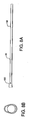
Figures 8A - 8F illustrate various views of an outer sheath suitable for use with the sheath lumens ofFigures 7A-7D ; -
Figures 9A - 9F illustrate various views of a distal window suitable for use with the apparatus ofFigure 1 ; -
Figure 10 illustrates an exploded view of the apparatus ofFigure 1 ; and, -
Figures 11A - 11C illustrate cross-sectional views of the apparatus ofFigure 2 , having an endoscope positioned at various positions therein for treatment. - It is to be understood that the figures and descriptions of the present invention have been simplified to illustrate elements that are relevant for a clear understanding of the present invention, while eliminating, for purposes of clarity, many other elements found in endoscopic systems and radiating treatment methods. Those of ordinary skill in the art will recognize that other elements are desirable and/or required in order to implement the present invention. However, because such elements are well known in the art, and because they do not facilitate a better understanding of the present invention, a discussion of such elements is not provided herein. The disclosure herein is directed to all such variations and modifications to such systems and methods known to those skilled in the art.
- According to an aspect of the present invention, a sheath like apparatus may be provided and used that may be advantageously compatible with existing endoscopic equipment, and be used to expand, directly view and irradiate target tissue within a body cavity or lumen. It should be understood that while endoscope sheaths have generally been developed in order to prevent pathogen transfer from a cavity in which the scope is placed to the instrument itself, and in turn from person to person, these devices typically provide no other significant therapeutic benefits or advantages.
- According to an aspect of the present invention, there is provided a sheath-like device which may be used in conjunction with, or otherwise associated with such as by substantially encasing, an endoscope and introduced into a body cavity or lumen. Such a device may allow the cavity or lumen, or portion thereof corresponding to a treatment area, to be formed or dilated to a desired shape, so as to be substantially spherical, cylindrical, ellipsoidal or ovoid, for example. According to an aspect of the present invention, such a device may provide means to inspect, diagnose and/or treat the cavity or lumen with electromagnetic radiation, such as light or acoustic energy such as ultrasound. Energy delivered in this manner may allow for more accurate diagnosis or treatment than may otherwise be conventionally possible. Provided energy may also effect treatment through direct physical effect on surrounding tissue, such as by cauterization or hypothermia, for example. Or, it may effect treatment by causing a chemical reaction, such as in conjunction with a photosensitizing agent or precursor present in target tissue, for example. According to an aspect of the present invention, enhanced visualization of the cavity or lumen being irradiated may be achieved.
- According to an aspect of the present invention, there may be provided and used a sheath-like apparatus into which an endoscope may be inserted, so as to facilitate examination and therapy within a biological cavity using a single insertion of the apparatus. Near an end of the apparatus, a bladder or balloon portion positionable with the aid of an elongated sheath portion may be provided. The balloon portion may be inflated with a suitable fluid, such as a liquid or gas, to thereby cause it to swell and provide an outward force that may tend to dilate or deform a biological cavity into which it is inserted. Such dilation may be of a desirably and predictably smooth shape based upon characteristics of the balloon so as to enhance uniformity or irradiation or illumination provided therethrough. For example, the balloon may be substantially non-distensible. Alternatively, it may be desirable that the balloon portion be distensible or partially distensible based upon intended operational characteristics.
- According to an aspect of the present invention, the apparatus may generally include a fitting which includes a seal housing, a seal which is dimensioned to receive an endoscope while creating a substantially air-tight seal about it, and a seal retainer. The apparatus may generally include a substantially transparent outer sheath including a non-distensible balloon a substantially transparent inner sheath; a substantially transparent viewing window; a tube positioned between the inner and outer sheaths being suitable for delivering at least one fluid, such as air, to a distal end of the treatment apparatus, such as to terminate distal to the balloon and/or viewing window for the evacuation of matter that may accumulate distal to the balloon and/or window during therapy; and a second tube which terminates within the seal housing and is intended to transport a fluid or air for the purpose of inflating the balloon. The viewing window may have an antireflection coating on one or more surfaces.
- The balloon may or may not have either a reflective, partially reflective or absorptive coating applied to one or more surfaces, or a portion thereof, to enhance and/or limit treatment to a specific target area of tissue within a cavity. The balloon may have an optical sensor or sensing fiber affixed to or embedded in it.
- By inserting an endoscope into the apparatus, sufficient rigidity may be attained to allow the apparatus to be inserted into a biological cavity such as an esophagus. Once inside the esophagus, a physician may examine the inside of the esophagus by looking through the transparent viewing window, rinse the interior of the esophagus with water or saline that is introduced through the apparatus, introduce air, suction liquid, and properly position the apparatus for therapy. When properly positioned, air may be introduced into the balloon causing the balloon to inflate. The inflated balloon may substantially anchor the apparatus in the biological cavity allowing the endoscope to be withdrawn a distance equivalent to a treatment length. The treatment length may be determined through the endoscope by visual reference to markings within the apparatus or by visual reference to graduations on the endoscope itself, for example. An energy delivering device, such as a light emitting fiber, may then be inserted through an instrument channel in the endoscope, until it contacts the viewing window or a distal end of the apparatus, thereby exposing a portion of the energy delivering device to the cavity, such as a length of light emitting fiber suitable for treating a treatment area of tissue, i.e., a treatment length.
- Referring now to
Figure 1 , there is shown an isometric view of anapparatus 10 according to an aspect of the present invention.Apparatus 10 generally includes three functional areas: aproximal fitting 20,sheath lumens 30 anddistal window 40. An air/water/suction line 12 and inflation/deflation line 14 are shown extending from theproximal fitting 20 of theapparatus 10. - Referring now also to
Figure 2 , there is shown an isometric view of theapparatus 10 ofFigure 1 having amedical device 50 partially inserted therein.Device 50 may generally take the form of an apparatus or instrument for visually examining the interior of a bodily canal or a hollow organ, such as the colon, bladder or stomach.Device 50 may take the form of an endoscope or gastroscope, for example.Device 50 may be referred to herein as an endoscope for purposes of non-limiting explanation only.Endoscope 50 passes throughproximal fitting 20 and into an enclosed space formed by thesheath lumens 30. Aradiation emitting device 60, such as a light emitting fiber, is shown extending through a biopsy or instrument channel ofendoscope 50. Of course, any device being suitable for emitting radiation at wavelengths selected for therapeutic benefit of tissue and being inserted intodevice 50 may be used. Additionally, emittingdevice 60 may be connected to an activating source so as to couple emitted radiation into a treatment cavity and cause irradiation of surrounding tissue. For example, wheredevice 60 takes the form of an optical fiber, a laser or other suitable light-generating device (not shown) optically coupled to the fiber may be used. Alternatively,device 60 may generate emitted radiation itself. - Terminal fittings of the air/water/
suction line 12 and the inflation/deflation line 14 may be respectively connected to sources of air, water, or suction and pressure/vacuum respectively (not shown).Endoscope 50 may be used in conjunction withapparatus 10, such thatproximal fitting 20 may provide a primary interface betweenapparatus 10 andendoscope 50.Proximal fitting 20 may further provide a grip by which to maneuverapparatus 10. - Referring now also to
Figure 3 ,proximal fitting 20 generally includes aseal retainer 70,seal 80 and sealhousing 90. Sealing may be largely accomplished using a suitable elastomeric material or, alternatively, a mechanically or pneumatically actuated seal.Seal retainer 70 and sealhousing 90 may be acrylic in nature, but may be formed of any suitable, non-porous material that would allow for a good bonding surface for the other components as will be understood by one possessing an ordinary skill in the pertinent arts.Seal 80 may be formed of a parylene coated silicone, but may be largely formed out of any suitable elastomeric material that may have applied to it, a friction reducing coating.Seal retainer 70,seal 80 andhousing 90 may be designed to take advantage of a repeatable manufacturing process, such as injection molding. - Referring now also to
Figures 4A - 4D , there are shown various views of a seal retainer suitable for use asseal retainer 70 ofFigure 3 .Seal retainer 70 may generally take the form of a truncated cone having a small taper suitable for creating a locking fit with a mating portion ofseal housing 90, as well to aid in ejection during a molding process, for example. A countersink like through hole oraperture 72 may be provided to guide a distal tip ofendoscope 50 into place so as to pass throughretainer 70 and into sheath portion 30 (Figs. 1 and2 ).Retainer 70 may also include two through holes orapertures 74 sized to fit a strain relief for inflation/deflation 12 and air/water suction 14 lines (Figs. 1 and2 ). Along an outer tapered surface ofretainer 70 may be provided a key likefeature 76 suitable for dictating positioning during assembly. This may serve to mitigate a risk of misalignment with mating holes inseal 80. Referring now also toFigures 5A - 5D , there are shown various views of a seal suitable for use asseal 80 ofFigure 3 .Seal 80 may be configured to provide multiple seals.Seal 80 may generally comprise aflat disk portion 82 and an o-ring-like gasket 84 that lies around a perimeter of thedisk 82 and atubular portion 86 extending longitudinally fromdisk 82.Seal 80 may further include abore 81 throughdisk 82 andtubular portion 86.Tubular portion 86 may be relatively thin walled to accommodatebore 81.Disk 82 and o-ring 84 may be compressed between a distal face ofseal retainer 70 and a step in a bore ofseal housing 90 when assembled therewith. -
Seal 80 may further include a plurality, such as four (4), fin likeprotrusions 83 extending outwardly from and alongtubular portion 86 ofseal 80. Of course, any suitable shape forportion 83 may be used though. These protrusions may serve to provide rigidity totubular portion 86 to prevent roll back upon removal ofendoscope 50. Second, when fully assembled inseal housing 90, the distal face of the fins may contact at least one protrusion within thehousing 90 to prevent elongation and therefore narrowing ofseal 80 whenendoscope 50 is inserted throughbore 81. -
Seal 80 may further includeapertures 89 passing throughdisk portion 82 and being suitable for passing air/water/suction line 12 and inflation/deflation line 14 therethrough.Apertures 89 may be undersized in comparison to tubes being passed through them. Further,disk 82 may include a relativelythicker portion 87 through which apertures 83 pass to provide a greater sealing surface along the length of the insertedlines seal 80.Portion 87 of increased thickness may also be configured to act as a key, forcing alignment ofapertures 89 of theseal 80 withapertures 74 through seal retainer 70 (Fig. 4A ) as well as with apertures throughseal housing 90 which correspond tolines -
Seal 80 may provide a seal betweenseal retainer 70 and sealhousing 90.Seal 80 may provide a seal aboutlines apertures 89.Seal 80 may provide for a seal between an inner wall oftubular portion 86 andendoscope 50 whenendoscope 50 is passed throughbore 81. An inner diameter oftubular portion 86 may be relatively undersized, such that whenendoscope 50 is passed therethrough,tubular portion 86 expands to allow endoscope passage. - Wall thickness and durometer of
silicone composing seal 80 may be adjusted during manufacturing to obtain desired radial force operability. By adjusting the seal length and applying a parylene coating during manufacturing, the friction between the seal and the scope can be adjusted to allow for smooth insertion and removal of the endoscope into and fromapparatus 10, for example. The desired friction may also be set so that movement ofendoscope 50 relative to thesheath assembly 10 should not inadvertently occur during use, absent force being applied toendoscope 50 by a physician, for example.Tubular portion 86 may be tapered at one or both longitudinal ends to ease insertion and/or removal ofendoscope 50, for example. As will be recognized by one possessing an ordinary skill in the pertinent arts, when all three seals are effected,apparatus 10 defines a substantially closed system that can be pressurized. - Referring now also to
Figures 6A - 6F , there are shown various views of a seal housing being suitable for use asseal housing 90 ofFigure 3 .Seal housing 90 may serve primarily as a transition piece fromseal 80 to sheath lumens 30 (Fig. 1 ).Housing 90 may generally take the form of a series of concentric cones forming a plurality of steps in an internal bore thereof, for example. -
Housing 90 may include aportion 92 adapted to receive and position sealretainer 70. A first step that decreases the inner diameter ofhousing 90 may mate withflat disk portion 82 ofseal 80, so as to cooperate as a sealing face. This first step may further include a small channel along its perimeter that mates with o-ring portion 84 ofseal 80. Asecond portion 94 may include internally projectingfins 95 similar to fins 83 (Fig. 5A ) to facilitate securingseal retainer 70 in a substantially centralized position within a bore ofhousing 90 and reduce seal elongation by retaining a proximal end ofseal 80.Fins 95 may be spaced to facilitate alignment ofseal 80. Substantially adjacent a longitudinal end ofportion 94 substantially distal toportion 92, a small thinwalled protrusion 93 that acts as a positive stop forfins 83 ofseal 80, preventing elongation upon endoscope insertion, may be provided. Further, twoapertures portion 94 substantially distal fromportion 92 may be provided. A larger of the twoapertures 99 may be substantially centralized and sized to allowendoscope 50 passage.Aperture 99 may also pass through a taperedprotrusion 98 that for a more proximal portion, substantially adjacent tosection 94, may be teardrop shaped in cross section. An exterior surface of the tear dropped portion ofprotrusion 98 may serve as a bonding site for an outer sheath, as will be discussed.Protrusion 98 may then step down to a substantially circular cross-section, which may serve as a bonding site for an inner sheath, as will be discussed.Aperture 97 may be smaller, and adapted to pass through only the teardrop shaped portion ofprotrusion 98, exiting at or near the step down to the smaller, substantially circular cross-section.Aperture 97 may be used to provide access to a space between inner and outer sheaths, allowing for passage of the air/water/suction line 12 and inflation/deflation line 14.Aperture 97 may be positioned with reference to other keying features in the proximal fitting components to allow for a straight run, or substantially straight run, of the air/water/suction line 12 and/or inflation/deflation line 14. - Referring now also to
Figures 7A - 7D , there are shown various views of a sheath lumens suitable for use assheath lumens 30 ofFigure 1 .Sheath lumens 30 generally includes aninner sheath 32, air/water/suction line 12, inflation/deflation line 14, and an outer sheath/balloon 34.Inner sheath 32 and outer sheath/balloon 34 may be formed of Polyethylene Terephthalate (PET). Air/water/suction line 12 and inflation/deflation line 14 may be formed of Pebax 72D. Of course, eithersheath lines - Generally,
inner sheath 32 may take the form of a thin walled (for example .001") tube that runs substantially the length of thesheath 30. A first end ofinner sheath 32 may be tapered to fit over the tapered, circular cross sectiondistal protrusion 98 ofseal housing 90. An inner diameter ofinner sheath 32 may be sized to allow passage ofendoscope 50 therethrough.Inner sheath 32 may also serve to effectively limit an area in which optical fiber 60 (Fig. 2 ) used in treatment will be able to wander. - Generally, air/water/
suction line 12 may be small in diameter (for example having a .072" outer diameter) and run substantially the length ofsheath 30.Line 12 may terminate substantially at or neardistal window 40. As set forth,line 12 may further pass throughproximal fitting 20. Further, from the proximal fitting 20 a length of tubing may continue as a pigtail, terminating at a luer lock fitting, for example. To prevent movement ofline 12, it may be banded toinner sheath 32. Accordingly,endoscope 50 may be effectively insulated from air/water/suction line 12 byinner sheath 32. - Generally, inflation/
deflation line 14 may be small in diameter (for example having a .072" outer diameter) and terminate in a substantially free floating manner within seal housing 90 (Fig. 6A ). As set forth,line 14 may further pass throughproximal fitting 20. Further, from the proximal fitting 20 a length of tubing may continue as a pigtail, terminating at a luer lock fitting, for example. To prevent movement ofline 14, it may also be banded toinner sheath 32. Accordingly,endoscope 50 may be effectively isolated from inflation/deflation line 14 byinner sheath 32. - Referring now also to 8A - 8F in conjunction with 7A - 7D in particular, there are shown various views of an outer sheath suitable for use as outer sheath/
balloon 34 ofFigures 7A - 7D . According to an aspect of the present invention, outer sheath/balloon 34 may be seen to generally include aproximal taper 100, a cylindricalmain lumen 102, aballoon 104 and adistal mating portion 106. The last two features can be a separate component from the other two, or integrally formed therewith. The outer sheath/balloon 34 may take the form of a thin walled (.001") tube. A cross section oftaper 100 may be generally tear drop in shape, designed to mate with theprotrusion 98 of the same shape ofseal housing 90. An elongated cylindricalmain lumen 102 may be set off-axis frominner sheath 32 so as to allow for the passage of the air/water/suction line 12. A small cavity may be formed betweeninner sheath 32 andouter sheath 34 along the length. The shape ofballoon portion 104 may at least partially depend on the type of biological cavity it is intended to be inflated in. In the illustrated, non-limiting instance it is shown as cylindrical, with an abrupt proximal and distal ending that may be suitable to fit within a patient's esophagus. The length and diameter of theballoon 104 cylinder can be manufactured in a variety of sizes depending on treatment requirements.Balloon 104 may also be coated on specific sections or in a pattern like manner to provide a specific treatment area, improve light efficiency to the treatment area, or improve uniformity, for example. Suitable coatings may be reflective, such as titanium oxide, gold, aluminum, silver or other metals in the case of light irradiation. Suitable coatings may be absorptive, such as carbon black in the case of light irradiation. Such coating may at least partially define treatment area within a biological cavity whichballoon 104 is inserted, by facilitating unidirectional irradiation for example.Balloon 104 may be semi-permeable, to allow an oxygenated fluid passage to tissue being treated.Distal mating portion 106 may be of a generally teardrop cross section that is designed to mate with distal window 40 (Fig. 1 ). Thissection 106 may be positioned so as to realign the axis of theouter sheath 34 to theinner sheath 32 and distal window 40 (Fig. 1 ). The balloon portion may be bonded to outer sheathmain lumen 102. - Referring now also to
Figures 9A - 9F , there are shown various views of a distal window suitable for use asdistal window 40 ofFigure 1 . Generally,distal window 40 may take the form of a substantially planar, non-planar or lens shaped member, by way of non-limiting example only, that may be made of acrylic to provide a substantially optically clear, non-distorting window. Of course, any other material that provides these features and may be bonded to may be acceptable for use.Window 40 generally includes a taperedprotrusion 42 with a circular cross section to provide a bonding site for inner sheath 32 (Figs 7A-7D ).Window 40 may then step up to a taperedsection 94 with a teardrop cross section suitable for providing a bonding site for outer sheath/balloon 34. Asmall ridge 46 may serve as a positive stop for outer sheath/balloon 34. Passing through the bonding site for the outer sheath/balloon 34 may be a small oval or ellipse shaped bore 48, which has a small step within it, and is hooded 49 on an end opposite toprotrusion 42.Bore 48 may be designed to accept a distal end of the air/water/suction line 12 such that the internal step is positioned to act as a positive stop preventing over insertion.Hood 49 may serve to direct a stream of fluid passing through air/water/suction line 12 down acrossdistal window 40. The deflecting surface of the hood may be angled so that the fluid passes over an outer surface ofwindow 40. Viewing windows may be placed at other positions relative to balloon 104 as will be well understood by those possessing an ordinary skill in the pertinent art though. Further, viewing may be facilitated directly throughballoon 104, for example, such thatballoon 104 itself forms a viewing window. - Referring now also to
Figure 10 , there is shown an exploded view of an embodiment ofapparatus 10 ofFigure 1 .Apparatus 10 ofFigure 10 may be assembled in the following manner.Inner sheath 32 may be adhered to sealhousing 90. The air/water/suction line 12 may be fed throughaperture 97 inseal housing 90 such that a length slightly longer than the distal end ofinner sheath 32 is provided. The air/water/suction line 12 may then be banded to theinner sheath 32. An area of theinner sheath 32 corresponding to balloon 104 is preferably not banded.Outer sheath 34 may then be adhered tohousing 90.Balloon 104 may then be slid onto theouter sheath 34 such that a distal end ofballoon 104 is behind, or shorter than, a distal end ofinner sheath 32. Air/water/suction line 12 may then be fed into and secured withinaperture 48 ofwindow 40, such as by adhering.Inner sheath 32 may then be adhered to the corresponding area ofportion 42 ofdistal window 40, taking care to ensure that the air/water/suction line 12 remains substantially in-line.Balloon 104 may then be adhered up to theridge 46 onwindow 40 and to theouter sheath 34.Seal 80 may then be inserted intoseal housing 90 while feeding air/water/suction line 12 through one of theapertures 89, such as a left one, taking care to ensure full seating ofseal 80. Inflation/deflation line 14 may then be fed through the other of theapertures 89 in theseal 80. The air/water/suction and inflation/deflation lines apertures 74 ofseal retainer 70.Seal retainer 70 may then be fully seated withinhousing 90 such that the proximal faces thereof are substantially in plane. The air/water/suction and inflation/deflation lines Strain reliefs 110 may then be slid onto and adhered to the ends of the air/water/suction and inflation/deflation lines deflation lines - In use,
endoscope 50 may be inserted through theseal retainer 70,seal 80 and sealhousing 90, and into theinner sheath 32 such that the distal end of theendoscope 50 becomes proximate to the distal end of the inner sheath 32 (i.e., adjacent to the viewing window 40). Whenendoscope 50 is fully inserted,sheaths rigid endoscope 50 housed within them and is ready to be used in a biological cavity (e.g., an esophagus). - When the distal portion of
endoscope 50 is proximate to the distal end of theinner sheath 32,endoscope 50 may be positioned to receive, and transmit, images of a cavity in which the sheath and endoscope are inserted; through theviewing window 40. If the viewing window becomes hazy or is covered by matter (which may be, for example, biological in nature), a physician can direct water or air through the air/water/suction line 12 to remove the matter from theviewing window 40. Similarly, if sufficiently small matter and/or fluid in nature should become adjacent towindow 40, the matter may be removed by sucking it through the air/water/suction line 12. - By injecting a suitable material, such as a gas, air or liquid for example, between the inner and
outer sheaths 32, 34 (by using inflation/deflation line 14 for example),balloon 104 will tend to inflate and deform a biologic cavity in which it is inserted. Similarly, if fluid pumped intoapparatus 10 is withdrawn (for example, by sucking the fluid back out through inflation/deflation line 12), the space between inner and outer sheaths and between the inner sheath and endoscope scope will deflate. - Referring now to
Figures 11A and 11B , there are illustrated cross-sectional views showing the distal end of theendoscope 50 at a first position proximate the distal end of theinner sheath 32 wherein theballoon 104 is in a deflated state and adjacent a target region of a biologic cavity. When in this first position, theballoon 104 may be inflated (by pumping air, water, etc. through theinflation line 12 to expand the target region by making a uniform shape, for example). Simultaneously, the space between the inner andouter sheaths - The target region may be affected by a disease or ailment such as Barrett's Esophagus and may additionally contain a photosensitizing agent or precursor such as that described in
U.S. Patent Nos. 5,955,490 ,5,422,093 ,5,234,940 ,5,211,938 ,5,097,262 and in James C. Kennedy et al. , Photodynamic Therapy (PDT) and Photodiagnosis (PD) Using Endogenous Photosensitization Induced by 5-Aminolevulinic Acid (ALA): Mechanisms and Clinical Results, 14 J. CLINICAL LASER MEDICINE & SURGERY 289-304 (1996). - After the
balloon 104 is inflated, the physician may pull on theendoscope 50 while holding theproximal fitting 20 thereby withdrawing theendoscope 50 relative to theviewing window 40; the endoscope being proximally withdrawn to a second position, thereby defining a treatment region between the distal end of theendoscope 50 and the proximal end of the viewing window 40 (Fig. 11B ). - Referring now also to
Figure 11C , after theendoscope 50 is withdrawn,light emitting fiber 60 may be extended through the bores ofapparatus 40, such that it projects into the treatment region between the distal end of theendoscope 50 and the proximal end of theviewing window 40. When thefiber 60 is extended, the physician may irradiate the target region with light. The light, which may take the form of laser emissions, passes through theinner sheath 32 and theballoon 104 of the outer sheath/balloon 34 and is absorbed by portions biologic cavity in which it is inserted, including the target region. The light delivered by the fiber may be in the infrared, visible, and/or ultraviolet regions of the spectrum, although if the intended treatment utilizes a photosensitizer, the wavelengths of light will be specific to those capable of activating said photosensitizer. The fiber that delivers the light may be configured in a variety of geometries including cylindrical, spherical and spot projection, with the preferred embodiment being cylindrical. - After the target region has been effectively treated, the combination of the
endoscope 50,inner sheath 32, andouter sheath 34 may be removed in a manner similar to that by which the combination was inserted. Specifically, thelight emitting fiber 60 may be withdrawn back into theendoscope 50, and theendoscope 50 is pushed back to the first position at which its distal end is proximate to the distal end of theinner sheath 32, while theballoon 104 remains inflated. Subsequently, theballoon 104 may be deflated. After deflating theballoon 104, the combination of theendoscope 50,inner sheath 32, andouter sheath 34 may be removed from the biologic cavity, such as an esophagus. Alternatively,apparatus 10 may be left in place to facilitate effecting other treatments or procedures, in which case endoscope 50 may be withdrawn, and if necessary or desirable,balloon 104 inflated to maintain its relative position in the cavity whileendoscope 50 is being withdrawn. - According to an aspect of the present invention, seal 80 may take the form of a locking or passive seal.
- According to an aspect of the present invention, air/water/
suction line 12 could be split into an air/water line and a suction line. The air/water line would continue to use the hood feature on the distal window for displacing the spray of fluid. The suction line may be provided with a separate bore through thedistal window 40 that was not hooded, to allow direct suction for example. An additional suction port could be positioned proximal to the balloon to remove fluid build up during treatment. According to an aspect of the present invention, air/water/suction line 12 could be removed altogether, which could allow for the removal of the outer sheath and the necessary bonding sites on theproximal fitting 20 anddistal window 40. In such a case,balloon 104 may be adhered proximally and distally to theinner sheath 32. Theinner sheath 32 may be allowed to communicate with theballoon 104. - According to an aspect of the present invention, air/water/
suction line 12 could be removed altogether, which could allow for the removal of the inner sheath and the necessary bonding sites on theproximal fitting 20 anddistal window 40. In such a case,balloon 104 may be adhered proximally and distally to the outer sheath. The outer sheath may be allowed to communicate with theballoon 104. - According to an aspect of the present invention, the inflation/deflation line could be removed and an air and suction feature inherent to endoscope 50 used to inflate and deflate the sheath respectively.
- According to an aspect of the present invention, markings may be provided so as to be viewable using
endoscope 50. According to an aspect of the present invention, reference points for determining a distance that the endoscope is withdrawn for treatment may take the form of markings at the distal end of the air/water/suction line 12 within the region of theballoon 104,inner sheath 32 orouter sheath 34, for example. This would allow the user to directly view how far backendoscope 50 is moved. - According to an aspect of the present invention, it may be desirable to at least partially inflate
balloon 104 to improve viewing throughwindow 40. - Although the aforementioned describes preferred embodiments of the invention, the invention is not so restricted. It will be apparent to those skilled in the art that various modifications and variations can be made to the disclosed preferred embodiments of the present invention without departing from the scope of the invention. For example, although the invention was described as being used in a esophagus, it could be used in any biological cavity sized to receive an endoscope (e.g., bladder, colon, etc.). In addition, although the invention was described as treating Barrett's Esophagus, it could be used to treat or diagnose other diseases or ailments such as colon or bladder cancer.
- According to an aspect of the present invention,
fiber 60 may be replaced by, or supplemented with, another medical treatment device or apparatus. By way of nonlimiting example, one or more ultrasound applicators could be sheathed byapparatus 10 so as to permit treatment, or the application of a procedure, to tissue via a cavity in whichapparatus 10 has been inserted. - Accordingly, it should be understood that the apparatus described herein is illustrative only and is not limiting upon the scope of the invention, which is indicated by the following claims. Accordingly, alternatives which would be clear to one of ordinary skill in the art upon reading the teachings herein disclosed, are hereby within the scope of this invention.
Claims (68)
- A medical device sheath apparatus (10) comprising:a fitting (20) being suitable for receiving said medical device (50) in a self sealing manner;a first sheath (32) for receiving said medical device as it passes through said fitting;a second sheath (34) surrounding said first sheath;a dilator defining a treatment area, coupled to at least said second sheath, and being suitable for dilating a bodily cavity and passing therapeutic electromagnetic radiation there through; and,a window (40) operatively positioned with respect to said first sheath so as to enable viewing of an area substantially adjacent said second sheath upon insertion of said medical device into said apparatuswherein said medical device comprises an endoscope comprising a channel suitable for deceiving an optical fiber suitable for irradiating biologic material through said dilator andthe medical device sheath apparatus further comprises a means for inflating at least said dilator and wherein said inflatable dilator is suitable for irradiating biological material through said dilator.
- The apparatus of Claim 1, wherein said dilator is substantially non-distensible.
- The apparatus of Claim 1, wherein said fitting comprise:a seal housing; and,a seal secured by said housing and comprising a bore being suitable for receiving said medical device and sized to provide an air seal against an outside diameter of said medical device.
- The apparatus of Claim 3, further comprising at least one additional bore being suitable for receiving at least one tube for inflating or deflating said dilator.
- The apparatus of Claim 3, wherein said seal comprises at least one elastomeric material.
- The apparatus of Claim 3, wherein said seal is mechanically or pneumatically actuatable.
- The apparatus of Claim 3, further comprising at least one retainer securing said seal to said housing.
- The apparatus of Claim 7, wherein said seal, housing and retainer are integral.
- The apparatus of Claim 1, further comprising a tube having an end positioned with respect to said window to enable introduction of a material substantially adjacent to said window through said fitting.
- The apparatus of Claim 1, further comprising a tube having an end positioned with respect to said window to enable evacuation of material from an area substantially adjacent to said window trough said fitting.
- The apparatus of Claim 1, wherein said window is substantially transparent.
- The apparatus of Claim 11, wherein said window comprises at least one anti-reflective coating.
- The apparatus of Claim 1, wherein said dilator further comprises at least one of a partially reflective coating and an absorptive coating.
- The apparatus of Claim 13, wherein said coating comprises at least one of gold, aluminum, silver, titanium oxide and carbon black.
- The apparatus of Claim 7, wherein at least two of said housing, seal and retainer are keyed.
- The apparatus of Claim 15, wherein said keying comprises at least one notch.
- The apparatus of Claim 7, wherein said seal comprises a plurality of fins suitable for mating with at least said housing or retainer.
- The apparatus of Claim 17, wherein at least one of said housing and retainer comprise a plurality of grooves suitable for receiving said fins.
- The apparatus of Claim 1, wherein said first and second sheaths are adapted such that said medical device provides sufficient rigidity to insert said apparatus into a bodily cavity.
- The apparatus of Claim 1, wherein said first sheath and fitting are coupled so as to permit a substantially distal portion of said medical device to be displaceable within said treatment area.
- The apparatus of Claim 1, wherein said means for inflating further comprises means for inflating said first sheath.
- The apparatus of Claim 1, further comprising at least one marking on said first sheath, second sheath or dilator being suitable for determining a position of a substantially distal portion of said medical device using said medical device.
- The apparatus of Claim 22, wherein said at least one marking is directly viewable.
- The apparatus of Claim 1, wherein said first sheath and fitting are configured to define a substantially closed space upon insertion of said medical device.
- The apparatus of Claim 24, wherein said dilator and first sheath define a second substantially closed space.
- The apparatus of Claim 7, wherein said retainer comprises a plurality of channels.
- The apparatus of Claim 26, wherein said housing comprises a plurality of projections positioned to mate with said channels when said retainer and housing are coupled to one another.
- The apparatus of Claim 3, wherein said seal comprises:a disc portions;an o-ring peripherally positioned with respect to said disk portion; and,a tubular portion extending from said disk portion;wherein said disk portion and tubular portion define at least one bore suitable for receiving said medical device there through.
- The apparatus of Claim 28, wherein said tubular portion comprises a plurality of radially outwardly extending protrusions.
- The apparatus of Claim 29, further comprising at least one aperture passing through said disk portion, wherein said disk portion is adapted to be compressed between said housing and retainer.
- The apparatus of Claim 30, wherein said housing defines an internal bore corresponding to said bore of said seal, and said housing bore comprises a plurality of internal steps.
- The apparatus of Claim 31, wherein said housing further comprises a first bonding location for said first sheath and a second bonding location for said second sheath.
- The apparatus of Claim 32, wherein said housing further comprise at least two substantially concentric cone portions defining said first and second bonding locations.
- A method of making a medical device sheath apparatus as claimed in any of claims 1 to 33 comprising:coupling a first sheath to a fitting being suitable for receiving said medical device in a self sealing manner;coupling a second sheath to said fitting so as to surround said first sheath;coupling a dilator defining a treatment area and being suitable for dilating a bodily cavity and passing therapeutic electromagnetic radiation or diagnostic energy there through to said second sheath; and,coupling said first sheath to a window operatively positioned with respect to said first sheath so as to enable viewing of an area substantially adjacent said second sheath upon insertion of said medical device into said apparatus,wherein said medical device comprises an endoscope comprising a channel suitable for receiving an optical fiber suitable for irradiating biologic material through said dilator and there is further provided a means for inflating at least said dilator and wherein said inflatable dilator is suitable for irradiating biological material through said dilator.
- The method of Claim 34, further comprising passing at least one air, water or section line through said fitting.
- The method of Claim 35, further comprising banding said at least one air, water or suction line to said inner sheath.
- The method of Claim 35, further comprising securing said at least one of air, water or suction line substantially adjacent to said window.
- The method of Claim 34, further comprising coupling said second sheath to said window.
- A medical device sheath apparatus according to claim 1 comprising:a seal being suitable for receiving said medical device through said fitting; said first sheath being suitable for receiving said medical device through said fitting and seal.
- The apparatus of Claim 39, wherein said endoscope comprises at least one of an irradiating fiber and ultrasound transducer.
- The apparatus of Claim 39, wherein at least one of said dilator and first sheath is substantially non-distensible.
- The apparatus of Claim 39, wherein at least one of said dilator and first sheath is substantially distensible.
- The apparatus of Claim 39, wherein said fitting comprises:a seal housing; and,a seal secured in said housing and comprising a bore being suitable for receiving said medical device and sized to provide an air seal against an outside diameter of said medical device.
- The apparatus of Claim 43, further comprising at least one retainer securing said seal to said housing.
- The apparatus of Claim 44, wherein said seal, housing and retainer are integral.
- The apparatus of Claim 43, further comprising at least one additional bore being suitable for receiving at least one tube for inflating or deflating said dilator.
- The apparatus of Claim 43, wherein said seal comprises at least one elastomeric material.
- The apparatus of Claim 43, wherein said seal is mechanically or pneumatically actuatable.
- The apparatus of Claim 39, further comprising a tube having an end positioned with respect to said window to enable introduction of a material substantially adjacent to said window through said fitting.
- The apparatus of Claim 39, further comprising a tube having an end positioned with respect to said window to enable evacuation of material from an area substantially adjacent to said window through said fitting.
- The apparatus of Claim 39, wherein said window is substantially transparent.
- The apparatus of Claim 51, wherein said window comprises at least one anti-reflective coating.
- The apparatus of Claim 39, wherein said dilator further comprises at least one of a reflective, partially reflective and absorptive coating.
- The apparatus of Claim 53, wherein said coating comprises at least one of gold, aluminum, silver, titanium oxide and carbon black.
- The apparatus of Claim 44, wherein at least two of said housing, seal and retainer are keyed.
- The apparatus of Claim 39, wherein said sheath is sufficiently flexible such that said medical device provides sufficient rigidity to insert said apparatus into a bodily cavity.
- The apparatus of Claim 39, wherein said sheath and fitting are coupled so as to permit a substantially distal portion of said medical device to be displaceable within said treatment area.
- The apparatus of Claim 39, further comprising means for inflating at least said dilator.
- The apparatus of Claim 58, wherein said means for inflating further comprises means for inflating said sheath.
- The apparatus of Claim 39, further comprising at least one marking on said sheath, medical device or dilator being suitable for determining a position of a substantially distal portion of said medical device.
- The apparatus of Claim 60, wherein said at least one marking is directly viewable using said medical device.
- The apparatus of Claim 39, wherein said sheath and fitting are configured to define a substantially closed space upon insertion of said medical device.
- The apparatus of Claim 60, further comprising a second sheath secured to said fitting such that said dilator and second sheath define a second substantially closed space.
- The apparatus of Claim 43, wherein said seal comprises:a disc portion;an o-ring peripherally positioned with respect to said disk portion; and,a tubular portion extending from said disk portion;wherein said disk portion and tubular portion define at least one bore suitable for receiving said medical device there through.
- The apparatus of Claim 64, further comprising at least one aperture passing through said disk portion, wherein said disk portion is adapted to be compressed between said housing and retainer.
- The apparatus of Claim 43, wherein said housing defines an internal bore corresponding to said bore of said seal, and said housing bore comprises a plurality of internal steps.
- The apparatus of Claim 66, wherein said housing further comprises a first bonding location for said first sheath and a second bonding location for said second sheath.
- The apparatus of Claim 67, wherein said housing further comprises at least two substantially concentric cone portions defining said first and second bonding locations.
Applications Claiming Priority (5)
| Application Number | Priority Date | Filing Date | Title |
|---|---|---|---|
| US41866402P | 2002-10-15 | 2002-10-15 | |
| US418664P | 2002-10-15 | ||
| US10/331,561 US6958035B2 (en) | 2002-10-15 | 2002-12-30 | Medical device sheath apparatus and method of making and using same |
| US331561 | 2002-12-30 | ||
| PCT/US2003/032529 WO2004034875A2 (en) | 2002-10-15 | 2003-10-15 | Medical device sheath apparatus and method |
Publications (3)
| Publication Number | Publication Date |
|---|---|
| EP1555928A2 EP1555928A2 (en) | 2005-07-27 |
| EP1555928A4 EP1555928A4 (en) | 2007-07-04 |
| EP1555928B1 true EP1555928B1 (en) | 2010-12-15 |
Family
ID=32072935
Family Applications (1)
| Application Number | Title | Priority Date | Filing Date |
|---|---|---|---|
| EP03777606A Expired - Lifetime EP1555928B1 (en) | 2002-10-15 | 2003-10-15 | Medical device sheath apparatus and method of making the same |
Country Status (13)
| Country | Link |
|---|---|
| US (2) | US6958035B2 (en) |
| EP (1) | EP1555928B1 (en) |
| JP (1) | JP2006507861A (en) |
| AT (1) | ATE491385T1 (en) |
| AU (1) | AU2003287083B2 (en) |
| BR (1) | BR0315359A (en) |
| CA (1) | CA2502494A1 (en) |
| DE (1) | DE60335400D1 (en) |
| IL (1) | IL168077A (en) |
| MX (1) | MXPA05004049A (en) |
| NO (1) | NO20052401L (en) |
| NZ (1) | NZ539487A (en) |
| WO (1) | WO2004034875A2 (en) |
Families Citing this family (667)
| Publication number | Priority date | Publication date | Assignee | Title |
|---|---|---|---|---|
| IL143258A0 (en) * | 2001-05-20 | 2002-04-21 | Given Imaging Ltd | A method for in vivo imaging of the gastrointestinal tract in unmodified conditions |
| EP1731087A3 (en) | 2000-07-14 | 2008-08-06 | Novadaq Technologies Inc. | Compact fluorescent endoscopy video system |
| WO2002102224A2 (en) | 2001-06-18 | 2002-12-27 | Given Imaging Ltd. | In vivo sensing device with a circuit board having rigid sections and flexible sections |
| JP3987312B2 (en) * | 2001-08-31 | 2007-10-10 | 株式会社東芝 | Semiconductor device manufacturing apparatus and manufacturing method, and semiconductor manufacturing apparatus cleaning method |
| US20060241496A1 (en) | 2002-01-15 | 2006-10-26 | Xillix Technologies Corp. | Filter for use with imaging endoscopes |
| US20050070949A1 (en) * | 2002-12-20 | 2005-03-31 | Bakos Gregory J. | Transparent dilator device and method of use |
| US7309344B2 (en) * | 2002-12-20 | 2007-12-18 | Ethicon Endo-Surgery, Inc. | Transparent dilator device and method of use |
| EP1588733B1 (en) * | 2003-01-30 | 2012-03-14 | Sumitomo Bakelite Co., Ltd. | Endoscope-equipped puncture balloon |
| US7112195B2 (en) * | 2003-04-21 | 2006-09-26 | Cynosure, Inc. | Esophageal lesion treatment method |
| US9060770B2 (en) | 2003-05-20 | 2015-06-23 | Ethicon Endo-Surgery, Inc. | Robotically-driven surgical instrument with E-beam driver |
| US20070084897A1 (en) | 2003-05-20 | 2007-04-19 | Shelton Frederick E Iv | Articulating surgical stapling instrument incorporating a two-piece e-beam firing mechanism |
| JP4594612B2 (en) * | 2003-11-27 | 2010-12-08 | オリンパス株式会社 | Insertion aid |
| US20080230054A1 (en) * | 2004-03-23 | 2008-09-25 | Stephen Nicholas Prineas | Oropharyngeal Airway Device |
| US11896225B2 (en) | 2004-07-28 | 2024-02-13 | Cilag Gmbh International | Staple cartridge comprising a pan |
| US8905977B2 (en) | 2004-07-28 | 2014-12-09 | Ethicon Endo-Surgery, Inc. | Surgical stapling instrument having an electroactive polymer actuated medical substance dispenser |
| US8215531B2 (en) | 2004-07-28 | 2012-07-10 | Ethicon Endo-Surgery, Inc. | Surgical stapling instrument having a medical substance dispenser |
| US9072535B2 (en) | 2011-05-27 | 2015-07-07 | Ethicon Endo-Surgery, Inc. | Surgical stapling instruments with rotatable staple deployment arrangements |
| US11998198B2 (en) | 2004-07-28 | 2024-06-04 | Cilag Gmbh International | Surgical stapling instrument incorporating a two-piece E-beam firing mechanism |
| JP2006055447A (en) * | 2004-08-20 | 2006-03-02 | Pentax Corp | Operation button for endoscope and endoscope |
| US7648457B2 (en) * | 2005-05-13 | 2010-01-19 | Ethicon Endo-Surgery, Inc. | Method of positioning a device on an endoscope |
| US20070194079A1 (en) | 2005-08-31 | 2007-08-23 | Hueil Joseph C | Surgical stapling device with staple drivers of different height |
| US8991676B2 (en) | 2007-03-15 | 2015-03-31 | Ethicon Endo-Surgery, Inc. | Surgical staple having a slidable crown |
| US11246590B2 (en) | 2005-08-31 | 2022-02-15 | Cilag Gmbh International | Staple cartridge including staple drivers having different unfired heights |
| US8800838B2 (en) | 2005-08-31 | 2014-08-12 | Ethicon Endo-Surgery, Inc. | Robotically-controlled cable-based surgical end effectors |
| US7934630B2 (en) | 2005-08-31 | 2011-05-03 | Ethicon Endo-Surgery, Inc. | Staple cartridges for forming staples having differing formed staple heights |
| US11484312B2 (en) | 2005-08-31 | 2022-11-01 | Cilag Gmbh International | Staple cartridge comprising a staple driver arrangement |
| US9237891B2 (en) | 2005-08-31 | 2016-01-19 | Ethicon Endo-Surgery, Inc. | Robotically-controlled surgical stapling devices that produce formed staples having different lengths |
| US7669746B2 (en) | 2005-08-31 | 2010-03-02 | Ethicon Endo-Surgery, Inc. | Staple cartridges for forming staples having differing formed staple heights |
| US10159482B2 (en) | 2005-08-31 | 2018-12-25 | Ethicon Llc | Fastener cartridge assembly comprising a fixed anvil and different staple heights |
| US20070106317A1 (en) | 2005-11-09 | 2007-05-10 | Shelton Frederick E Iv | Hydraulically and electrically actuated articulation joints for surgical instruments |
| US20110024477A1 (en) | 2009-02-06 | 2011-02-03 | Hall Steven G | Driven Surgical Stapler Improvements |
| US9861359B2 (en) | 2006-01-31 | 2018-01-09 | Ethicon Llc | Powered surgical instruments with firing system lockout arrangements |
| US8161977B2 (en) | 2006-01-31 | 2012-04-24 | Ethicon Endo-Surgery, Inc. | Accessing data stored in a memory of a surgical instrument |
| US11224427B2 (en) | 2006-01-31 | 2022-01-18 | Cilag Gmbh International | Surgical stapling system including a console and retraction assembly |
| US11278279B2 (en) | 2006-01-31 | 2022-03-22 | Cilag Gmbh International | Surgical instrument assembly |
| US11793518B2 (en) | 2006-01-31 | 2023-10-24 | Cilag Gmbh International | Powered surgical instruments with firing system lockout arrangements |
| US8763879B2 (en) | 2006-01-31 | 2014-07-01 | Ethicon Endo-Surgery, Inc. | Accessing data stored in a memory of surgical instrument |
| US7845537B2 (en) | 2006-01-31 | 2010-12-07 | Ethicon Endo-Surgery, Inc. | Surgical instrument having recording capabilities |
| US8186555B2 (en) | 2006-01-31 | 2012-05-29 | Ethicon Endo-Surgery, Inc. | Motor-driven surgical cutting and fastening instrument with mechanical closure system |
| US20120292367A1 (en) | 2006-01-31 | 2012-11-22 | Ethicon Endo-Surgery, Inc. | Robotically-controlled end effector |
| US8708213B2 (en) | 2006-01-31 | 2014-04-29 | Ethicon Endo-Surgery, Inc. | Surgical instrument having a feedback system |
| US20110295295A1 (en) | 2006-01-31 | 2011-12-01 | Ethicon Endo-Surgery, Inc. | Robotically-controlled surgical instrument having recording capabilities |
| US7753904B2 (en) | 2006-01-31 | 2010-07-13 | Ethicon Endo-Surgery, Inc. | Endoscopic surgical instrument with a handle that can articulate with respect to the shaft |
| US8820603B2 (en) | 2006-01-31 | 2014-09-02 | Ethicon Endo-Surgery, Inc. | Accessing data stored in a memory of a surgical instrument |
| WO2007106624A2 (en) | 2006-02-07 | 2007-09-20 | Novadaq Technologies Inc. | Near infrared imaging |
| US20070185383A1 (en) * | 2006-02-08 | 2007-08-09 | Vision-Sciences, Inc. | Tapered endoscopic protective sheath |
| US8236010B2 (en) | 2006-03-23 | 2012-08-07 | Ethicon Endo-Surgery, Inc. | Surgical fastener and cutter with mimicking end effector |
| US8721630B2 (en) | 2006-03-23 | 2014-05-13 | Ethicon Endo-Surgery, Inc. | Methods and devices for controlling articulation |
| US8992422B2 (en) | 2006-03-23 | 2015-03-31 | Ethicon Endo-Surgery, Inc. | Robotically-controlled endoscopic accessory channel |
| US8322455B2 (en) | 2006-06-27 | 2012-12-04 | Ethicon Endo-Surgery, Inc. | Manually driven surgical cutting and fastening instrument |
| AU2007269043A1 (en) * | 2006-07-07 | 2008-01-10 | Alan Kessler | Channeled flexible sleeve for medical articles |
| US7740159B2 (en) | 2006-08-02 | 2010-06-22 | Ethicon Endo-Surgery, Inc. | Pneumatically powered surgical cutting and fastening instrument with a variable control of the actuating rate of firing with mechanical power assist |
| WO2008021254A2 (en) * | 2006-08-11 | 2008-02-21 | Ev3 Inc. | Rapid exchange catheters for embolic protection devices |
| US10130359B2 (en) | 2006-09-29 | 2018-11-20 | Ethicon Llc | Method for forming a staple |
| US8348131B2 (en) | 2006-09-29 | 2013-01-08 | Ethicon Endo-Surgery, Inc. | Surgical stapling instrument with mechanical indicator to show levels of tissue compression |
| US10568652B2 (en) | 2006-09-29 | 2020-02-25 | Ethicon Llc | Surgical staples having attached drivers of different heights and stapling instruments for deploying the same |
| US11980366B2 (en) | 2006-10-03 | 2024-05-14 | Cilag Gmbh International | Surgical instrument |
| US9345462B2 (en) | 2006-12-01 | 2016-05-24 | Boston Scientific Scimed, Inc. | Direct drive endoscopy systems and methods |
| US8632535B2 (en) | 2007-01-10 | 2014-01-21 | Ethicon Endo-Surgery, Inc. | Interlock and surgical instrument including same |
| US8684253B2 (en) | 2007-01-10 | 2014-04-01 | Ethicon Endo-Surgery, Inc. | Surgical instrument with wireless communication between a control unit of a robotic system and remote sensor |
| US11291441B2 (en) | 2007-01-10 | 2022-04-05 | Cilag Gmbh International | Surgical instrument with wireless communication between control unit and remote sensor |
| US8459520B2 (en) | 2007-01-10 | 2013-06-11 | Ethicon Endo-Surgery, Inc. | Surgical instrument with wireless communication between control unit and remote sensor |
| US8652120B2 (en) | 2007-01-10 | 2014-02-18 | Ethicon Endo-Surgery, Inc. | Surgical instrument with wireless communication between control unit and sensor transponders |
| US7434717B2 (en) | 2007-01-11 | 2008-10-14 | Ethicon Endo-Surgery, Inc. | Apparatus for closing a curved anvil of a surgical stapling device |
| US11039836B2 (en) | 2007-01-11 | 2021-06-22 | Cilag Gmbh International | Staple cartridge for use with a surgical stapling instrument |
| US7655004B2 (en) | 2007-02-15 | 2010-02-02 | Ethicon Endo-Surgery, Inc. | Electroporation ablation apparatus, system, and method |
| US7815662B2 (en) | 2007-03-08 | 2010-10-19 | Ethicon Endo-Surgery, Inc. | Surgical suture anchors and deployment device |
| EP2124711A4 (en) * | 2007-03-16 | 2011-03-30 | Univ Nanyang Tech | Method and apparatus for anorectal examination |
| US8893946B2 (en) | 2007-03-28 | 2014-11-25 | Ethicon Endo-Surgery, Inc. | Laparoscopic tissue thickness and clamp load measuring devices |
| US8075572B2 (en) | 2007-04-26 | 2011-12-13 | Ethicon Endo-Surgery, Inc. | Surgical suturing apparatus |
| US8100922B2 (en) | 2007-04-27 | 2012-01-24 | Ethicon Endo-Surgery, Inc. | Curved needle suturing tool |
| US8157145B2 (en) | 2007-05-31 | 2012-04-17 | Ethicon Endo-Surgery, Inc. | Pneumatically powered surgical cutting and fastening instrument with electrical feedback |
| US7832408B2 (en) | 2007-06-04 | 2010-11-16 | Ethicon Endo-Surgery, Inc. | Surgical instrument having a directional switching mechanism |
| US8931682B2 (en) | 2007-06-04 | 2015-01-13 | Ethicon Endo-Surgery, Inc. | Robotically-controlled shaft based rotary drive systems for surgical instruments |
| US11564682B2 (en) | 2007-06-04 | 2023-01-31 | Cilag Gmbh International | Surgical stapler device |
| US8534528B2 (en) | 2007-06-04 | 2013-09-17 | Ethicon Endo-Surgery, Inc. | Surgical instrument having a multiple rate directional switching mechanism |
| US7905380B2 (en) | 2007-06-04 | 2011-03-15 | Ethicon Endo-Surgery, Inc. | Surgical instrument having a multiple rate directional switching mechanism |
| US20090023985A1 (en) * | 2007-06-14 | 2009-01-22 | Usgi Medical, Inc. | Endoluminal instrument management system |
| US8408439B2 (en) | 2007-06-22 | 2013-04-02 | Ethicon Endo-Surgery, Inc. | Surgical stapling instrument with an articulatable end effector |
| US7753245B2 (en) | 2007-06-22 | 2010-07-13 | Ethicon Endo-Surgery, Inc. | Surgical stapling instruments |
| US11849941B2 (en) | 2007-06-29 | 2023-12-26 | Cilag Gmbh International | Staple cartridge having staple cavities extending at a transverse angle relative to a longitudinal cartridge axis |
| US20090054728A1 (en) * | 2007-08-21 | 2009-02-26 | Trusty Robert M | Manipulatable guide system and methods for natural orifice translumenal endoscopic surgery |
| US8262655B2 (en) | 2007-11-21 | 2012-09-11 | Ethicon Endo-Surgery, Inc. | Bipolar forceps |
| US8568410B2 (en) | 2007-08-31 | 2013-10-29 | Ethicon Endo-Surgery, Inc. | Electrical ablation surgical instruments |
| US8579897B2 (en) | 2007-11-21 | 2013-11-12 | Ethicon Endo-Surgery, Inc. | Bipolar forceps |
| US8480657B2 (en) | 2007-10-31 | 2013-07-09 | Ethicon Endo-Surgery, Inc. | Detachable distal overtube section and methods for forming a sealable opening in the wall of an organ |
| US20090112059A1 (en) | 2007-10-31 | 2009-04-30 | Nobis Rudolph H | Apparatus and methods for closing a gastrotomy |
| JP5246684B2 (en) * | 2007-12-27 | 2013-07-24 | 学校法人立命館 | Method for producing porous body and structure having porous body |
| US8287469B2 (en) | 2008-01-09 | 2012-10-16 | Ethicon Endo-Surgery, Inc. | Articulating surgical device and method of use |
| US8348129B2 (en) | 2009-10-09 | 2013-01-08 | Ethicon Endo-Surgery, Inc. | Surgical stapler having a closure mechanism |
| US8561870B2 (en) | 2008-02-13 | 2013-10-22 | Ethicon Endo-Surgery, Inc. | Surgical stapling instrument |
| US8453908B2 (en) | 2008-02-13 | 2013-06-04 | Ethicon Endo-Surgery, Inc. | Surgical stapling instrument with improved firing trigger arrangement |
| US7766209B2 (en) | 2008-02-13 | 2010-08-03 | Ethicon Endo-Surgery, Inc. | Surgical stapling instrument with improved firing trigger arrangement |
| US7905381B2 (en) | 2008-09-19 | 2011-03-15 | Ethicon Endo-Surgery, Inc. | Surgical stapling instrument with cutting member arrangement |
| US8540133B2 (en) | 2008-09-19 | 2013-09-24 | Ethicon Endo-Surgery, Inc. | Staple cartridge |
| US8758391B2 (en) | 2008-02-14 | 2014-06-24 | Ethicon Endo-Surgery, Inc. | Interchangeable tools for surgical instruments |
| US7819298B2 (en) | 2008-02-14 | 2010-10-26 | Ethicon Endo-Surgery, Inc. | Surgical stapling apparatus with control features operable with one hand |
| JP5410110B2 (en) | 2008-02-14 | 2014-02-05 | エシコン・エンド−サージェリィ・インコーポレイテッド | Surgical cutting / fixing instrument with RF electrode |
| US8622274B2 (en) | 2008-02-14 | 2014-01-07 | Ethicon Endo-Surgery, Inc. | Motorized cutting and fastening instrument having control circuit for optimizing battery usage |
| US9179912B2 (en) | 2008-02-14 | 2015-11-10 | Ethicon Endo-Surgery, Inc. | Robotically-controlled motorized surgical cutting and fastening instrument |
| US8573465B2 (en) | 2008-02-14 | 2013-11-05 | Ethicon Endo-Surgery, Inc. | Robotically-controlled surgical end effector system with rotary actuated closure systems |
| US7866527B2 (en) | 2008-02-14 | 2011-01-11 | Ethicon Endo-Surgery, Inc. | Surgical stapling apparatus with interlockable firing system |
| US8752749B2 (en) | 2008-02-14 | 2014-06-17 | Ethicon Endo-Surgery, Inc. | Robotically-controlled disposable motor-driven loading unit |
| US11986183B2 (en) | 2008-02-14 | 2024-05-21 | Cilag Gmbh International | Surgical cutting and fastening instrument comprising a plurality of sensors to measure an electrical parameter |
| US7793812B2 (en) | 2008-02-14 | 2010-09-14 | Ethicon Endo-Surgery, Inc. | Disposable motor-driven loading unit for use with a surgical cutting and stapling apparatus |
| US8584919B2 (en) | 2008-02-14 | 2013-11-19 | Ethicon Endo-Sugery, Inc. | Surgical stapling apparatus with load-sensitive firing mechanism |
| US8636736B2 (en) | 2008-02-14 | 2014-01-28 | Ethicon Endo-Surgery, Inc. | Motorized surgical cutting and fastening instrument |
| US8657174B2 (en) | 2008-02-14 | 2014-02-25 | Ethicon Endo-Surgery, Inc. | Motorized surgical cutting and fastening instrument having handle based power source |
| US10390823B2 (en) | 2008-02-15 | 2019-08-27 | Ethicon Llc | End effector comprising an adjunct |
| US11272927B2 (en) | 2008-02-15 | 2022-03-15 | Cilag Gmbh International | Layer arrangements for surgical staple cartridges |
| US8608044B2 (en) | 2008-02-15 | 2013-12-17 | Ethicon Endo-Surgery, Inc. | Feedback and lockout mechanism for surgical instrument |
| US20090206139A1 (en) | 2008-02-15 | 2009-08-20 | Ethicon Endo-Surgery, Inc. | Buttress material for a surgical instrument |
| US20090206131A1 (en) | 2008-02-15 | 2009-08-20 | Ethicon Endo-Surgery, Inc. | End effector coupling arrangements for a surgical cutting and stapling instrument |
| US8262680B2 (en) | 2008-03-10 | 2012-09-11 | Ethicon Endo-Surgery, Inc. | Anastomotic device |
| US8114072B2 (en) | 2008-05-30 | 2012-02-14 | Ethicon Endo-Surgery, Inc. | Electrical ablation device |
| US8679003B2 (en) | 2008-05-30 | 2014-03-25 | Ethicon Endo-Surgery, Inc. | Surgical device and endoscope including same |
| US8652150B2 (en) | 2008-05-30 | 2014-02-18 | Ethicon Endo-Surgery, Inc. | Multifunction surgical device |
| US8070759B2 (en) | 2008-05-30 | 2011-12-06 | Ethicon Endo-Surgery, Inc. | Surgical fastening device |
| US8317806B2 (en) | 2008-05-30 | 2012-11-27 | Ethicon Endo-Surgery, Inc. | Endoscopic suturing tension controlling and indication devices |
| US8771260B2 (en) | 2008-05-30 | 2014-07-08 | Ethicon Endo-Surgery, Inc. | Actuating and articulating surgical device |
| US8906035B2 (en) | 2008-06-04 | 2014-12-09 | Ethicon Endo-Surgery, Inc. | Endoscopic drop off bag |
| US8403926B2 (en) | 2008-06-05 | 2013-03-26 | Ethicon Endo-Surgery, Inc. | Manually articulating devices |
| US8361112B2 (en) | 2008-06-27 | 2013-01-29 | Ethicon Endo-Surgery, Inc. | Surgical suture arrangement |
| US8888792B2 (en) | 2008-07-14 | 2014-11-18 | Ethicon Endo-Surgery, Inc. | Tissue apposition clip application devices and methods |
| US8262563B2 (en) | 2008-07-14 | 2012-09-11 | Ethicon Endo-Surgery, Inc. | Endoscopic translumenal articulatable steerable overtube |
| US8211125B2 (en) | 2008-08-15 | 2012-07-03 | Ethicon Endo-Surgery, Inc. | Sterile appliance delivery device for endoscopic procedures |
| US8529563B2 (en) | 2008-08-25 | 2013-09-10 | Ethicon Endo-Surgery, Inc. | Electrical ablation devices |
| US8241204B2 (en) | 2008-08-29 | 2012-08-14 | Ethicon Endo-Surgery, Inc. | Articulating end cap |
| US8480689B2 (en) | 2008-09-02 | 2013-07-09 | Ethicon Endo-Surgery, Inc. | Suturing device |
| US8409200B2 (en) | 2008-09-03 | 2013-04-02 | Ethicon Endo-Surgery, Inc. | Surgical grasping device |
| US8114119B2 (en) | 2008-09-09 | 2012-02-14 | Ethicon Endo-Surgery, Inc. | Surgical grasping device |
| US8083120B2 (en) | 2008-09-18 | 2011-12-27 | Ethicon Endo-Surgery, Inc. | End effector for use with a surgical cutting and stapling instrument |
| PL3476312T3 (en) | 2008-09-19 | 2024-03-11 | Ethicon Llc | Surgical stapler with apparatus for adjusting staple height |
| US9050083B2 (en) | 2008-09-23 | 2015-06-09 | Ethicon Endo-Surgery, Inc. | Motorized surgical instrument |
| US9386983B2 (en) | 2008-09-23 | 2016-07-12 | Ethicon Endo-Surgery, Llc | Robotically-controlled motorized surgical instrument |
| US9005230B2 (en) | 2008-09-23 | 2015-04-14 | Ethicon Endo-Surgery, Inc. | Motorized surgical instrument |
| US11648005B2 (en) | 2008-09-23 | 2023-05-16 | Cilag Gmbh International | Robotically-controlled motorized surgical instrument with an end effector |
| US8210411B2 (en) | 2008-09-23 | 2012-07-03 | Ethicon Endo-Surgery, Inc. | Motor-driven surgical cutting instrument |
| US8337394B2 (en) | 2008-10-01 | 2012-12-25 | Ethicon Endo-Surgery, Inc. | Overtube with expandable tip |
| US8608045B2 (en) | 2008-10-10 | 2013-12-17 | Ethicon Endo-Sugery, Inc. | Powered surgical cutting and stapling apparatus with manually retractable firing system |
| US9867529B2 (en) * | 2008-11-07 | 2018-01-16 | Izoscope Inc | Endoscope accessory |
| US8157834B2 (en) | 2008-11-25 | 2012-04-17 | Ethicon Endo-Surgery, Inc. | Rotational coupling device for surgical instrument with flexible actuators |
| US8172772B2 (en) | 2008-12-11 | 2012-05-08 | Ethicon Endo-Surgery, Inc. | Specimen retrieval device |
| US8361066B2 (en) | 2009-01-12 | 2013-01-29 | Ethicon Endo-Surgery, Inc. | Electrical ablation devices |
| US8828031B2 (en) | 2009-01-12 | 2014-09-09 | Ethicon Endo-Surgery, Inc. | Apparatus for forming an anastomosis |
| US9226772B2 (en) | 2009-01-30 | 2016-01-05 | Ethicon Endo-Surgery, Inc. | Surgical device |
| US8252057B2 (en) | 2009-01-30 | 2012-08-28 | Ethicon Endo-Surgery, Inc. | Surgical access device |
| US8037591B2 (en) | 2009-02-02 | 2011-10-18 | Ethicon Endo-Surgery, Inc. | Surgical scissors |
| US8397971B2 (en) | 2009-02-05 | 2013-03-19 | Ethicon Endo-Surgery, Inc. | Sterilizable surgical instrument |
| US8414577B2 (en) | 2009-02-05 | 2013-04-09 | Ethicon Endo-Surgery, Inc. | Surgical instruments and components for use in sterile environments |
| US8517239B2 (en) | 2009-02-05 | 2013-08-27 | Ethicon Endo-Surgery, Inc. | Surgical stapling instrument comprising a magnetic element driver |
| US8485413B2 (en) | 2009-02-05 | 2013-07-16 | Ethicon Endo-Surgery, Inc. | Surgical stapling instrument comprising an articulation joint |
| US8444036B2 (en) | 2009-02-06 | 2013-05-21 | Ethicon Endo-Surgery, Inc. | Motor driven surgical fastener device with mechanisms for adjusting a tissue gap within the end effector |
| US8453907B2 (en) | 2009-02-06 | 2013-06-04 | Ethicon Endo-Surgery, Inc. | Motor driven surgical fastener device with cutting member reversing mechanism |
| EP2393430A1 (en) | 2009-02-06 | 2011-12-14 | Ethicon Endo-Surgery, Inc. | Driven surgical stapler improvements |
| US8066167B2 (en) | 2009-03-23 | 2011-11-29 | Ethicon Endo-Surgery, Inc. | Circular surgical stapling instrument with anvil locking system |
| US8870752B2 (en) | 2009-03-25 | 2014-10-28 | The Cleveland Clinic Foundation | Medical device sheath |
| US9254123B2 (en) | 2009-04-29 | 2016-02-09 | Hansen Medical, Inc. | Flexible and steerable elongate instruments with shape control and support elements |
| WO2010144419A2 (en) | 2009-06-08 | 2010-12-16 | Surgivision, Inc. | Mri-guided interventional systems that can track and generate dynamic visualizations of flexible intrabody devices in near real time |
| JP2012529977A (en) | 2009-06-16 | 2012-11-29 | エムアールアイ・インターヴェンションズ,インコーポレイテッド | MRI guidance device and MRI guidance intervention system capable of tracking the device in near real time and generating a dynamic visualization of the device |
| US8516691B2 (en) | 2009-06-24 | 2013-08-27 | Given Imaging Ltd. | Method of assembly of an in vivo imaging device with a flexible circuit board |
| US20110098704A1 (en) | 2009-10-28 | 2011-04-28 | Ethicon Endo-Surgery, Inc. | Electrical ablation devices |
| US8608652B2 (en) | 2009-11-05 | 2013-12-17 | Ethicon Endo-Surgery, Inc. | Vaginal entry surgical devices, kit, system, and method |
| US8353438B2 (en) | 2009-11-19 | 2013-01-15 | Ethicon Endo-Surgery, Inc. | Circular stapler introducer with rigid cap assembly configured for easy removal |
| US8136712B2 (en) | 2009-12-10 | 2012-03-20 | Ethicon Endo-Surgery, Inc. | Surgical stapler with discrete staple height adjustment and tactile feedback |
| US8353487B2 (en) | 2009-12-17 | 2013-01-15 | Ethicon Endo-Surgery, Inc. | User interface support devices for endoscopic surgical instruments |
| US8496574B2 (en) | 2009-12-17 | 2013-07-30 | Ethicon Endo-Surgery, Inc. | Selectively positionable camera for surgical guide tube assembly |
| US8506564B2 (en) | 2009-12-18 | 2013-08-13 | Ethicon Endo-Surgery, Inc. | Surgical instrument comprising an electrode |
| US9028483B2 (en) | 2009-12-18 | 2015-05-12 | Ethicon Endo-Surgery, Inc. | Surgical instrument comprising an electrode |
| JP5535611B2 (en) * | 2009-12-22 | 2014-07-02 | 日本コヴィディエン株式会社 | Endoscope cover fixing tool |
| US8220688B2 (en) | 2009-12-24 | 2012-07-17 | Ethicon Endo-Surgery, Inc. | Motor-driven surgical cutting instrument with electric actuator directional control assembly |
| US8851354B2 (en) | 2009-12-24 | 2014-10-07 | Ethicon Endo-Surgery, Inc. | Surgical cutting instrument that analyzes tissue thickness |
| US8267300B2 (en) | 2009-12-30 | 2012-09-18 | Ethicon Endo-Surgery, Inc. | Dampening device for endoscopic surgical stapler |
| US8608046B2 (en) | 2010-01-07 | 2013-12-17 | Ethicon Endo-Surgery, Inc. | Test device for a surgical tool |
| US8177596B2 (en) * | 2010-01-22 | 2012-05-15 | Skysight Technologies Llc | Fishing trawler net resistant subsurface buoy tether system |
| US8177595B2 (en) * | 2010-01-22 | 2012-05-15 | Skysight Technologies Llc | Scoop point buoy |
| US9005198B2 (en) | 2010-01-29 | 2015-04-14 | Ethicon Endo-Surgery, Inc. | Surgical instrument comprising an electrode |
| EP2575590B2 (en) | 2010-05-25 | 2018-12-26 | Arc Medical Design Limited | Covering for a medical scoping device |
| US8789740B2 (en) | 2010-07-30 | 2014-07-29 | Ethicon Endo-Surgery, Inc. | Linear cutting and stapling device with selectively disengageable cutting member |
| US8783543B2 (en) | 2010-07-30 | 2014-07-22 | Ethicon Endo-Surgery, Inc. | Tissue acquisition arrangements and methods for surgical stapling devices |
| US8672207B2 (en) | 2010-07-30 | 2014-03-18 | Ethicon Endo-Surgery, Inc. | Transwall visualization arrangements and methods for surgical circular staplers |
| US8360296B2 (en) | 2010-09-09 | 2013-01-29 | Ethicon Endo-Surgery, Inc. | Surgical stapling head assembly with firing lockout for a surgical stapler |
| US9289212B2 (en) | 2010-09-17 | 2016-03-22 | Ethicon Endo-Surgery, Inc. | Surgical instruments and batteries for surgical instruments |
| US20120071752A1 (en) | 2010-09-17 | 2012-03-22 | Sewell Christopher M | User interface and method for operating a robotic medical system |
| US8632525B2 (en) | 2010-09-17 | 2014-01-21 | Ethicon Endo-Surgery, Inc. | Power control arrangements for surgical instruments and batteries |
| US20120078244A1 (en) | 2010-09-24 | 2012-03-29 | Worrell Barry C | Control features for articulating surgical device |
| US8733613B2 (en) | 2010-09-29 | 2014-05-27 | Ethicon Endo-Surgery, Inc. | Staple cartridge |
| US9168038B2 (en) | 2010-09-30 | 2015-10-27 | Ethicon Endo-Surgery, Inc. | Staple cartridge comprising a tissue thickness compensator |
| US9320523B2 (en) | 2012-03-28 | 2016-04-26 | Ethicon Endo-Surgery, Llc | Tissue thickness compensator comprising tissue ingrowth features |
| US8893949B2 (en) | 2010-09-30 | 2014-11-25 | Ethicon Endo-Surgery, Inc. | Surgical stapler with floating anvil |
| US9414838B2 (en) | 2012-03-28 | 2016-08-16 | Ethicon Endo-Surgery, Llc | Tissue thickness compensator comprised of a plurality of materials |
| US9241714B2 (en) | 2011-04-29 | 2016-01-26 | Ethicon Endo-Surgery, Inc. | Tissue thickness compensator and method for making the same |
| US9592050B2 (en) | 2010-09-30 | 2017-03-14 | Ethicon Endo-Surgery, Llc | End effector comprising a distal tissue abutment member |
| US9220500B2 (en) | 2010-09-30 | 2015-12-29 | Ethicon Endo-Surgery, Inc. | Tissue thickness compensator comprising structure to produce a resilient load |
| US9314246B2 (en) | 2010-09-30 | 2016-04-19 | Ethicon Endo-Surgery, Llc | Tissue stapler having a thickness compensator incorporating an anti-inflammatory agent |
| AU2011308701B2 (en) | 2010-09-30 | 2013-11-14 | Ethicon Endo-Surgery, Inc. | Fastener system comprising a retention matrix and an alignment matrix |
| US9332974B2 (en) | 2010-09-30 | 2016-05-10 | Ethicon Endo-Surgery, Llc | Layered tissue thickness compensator |
| US10945731B2 (en) | 2010-09-30 | 2021-03-16 | Ethicon Llc | Tissue thickness compensator comprising controlled release and expansion |
| US9204880B2 (en) | 2012-03-28 | 2015-12-08 | Ethicon Endo-Surgery, Inc. | Tissue thickness compensator comprising capsules defining a low pressure environment |
| US9629814B2 (en) | 2010-09-30 | 2017-04-25 | Ethicon Endo-Surgery, Llc | Tissue thickness compensator configured to redistribute compressive forces |
| US9216019B2 (en) | 2011-09-23 | 2015-12-22 | Ethicon Endo-Surgery, Inc. | Surgical stapler with stationary staple drivers |
| US11812965B2 (en) | 2010-09-30 | 2023-11-14 | Cilag Gmbh International | Layer of material for a surgical end effector |
| US9364233B2 (en) | 2010-09-30 | 2016-06-14 | Ethicon Endo-Surgery, Llc | Tissue thickness compensators for circular surgical staplers |
| US9232941B2 (en) | 2010-09-30 | 2016-01-12 | Ethicon Endo-Surgery, Inc. | Tissue thickness compensator comprising a reservoir |
| US11849952B2 (en) | 2010-09-30 | 2023-12-26 | Cilag Gmbh International | Staple cartridge comprising staples positioned within a compressible portion thereof |
| US11298125B2 (en) | 2010-09-30 | 2022-04-12 | Cilag Gmbh International | Tissue stapler having a thickness compensator |
| US8925782B2 (en) | 2010-09-30 | 2015-01-06 | Ethicon Endo-Surgery, Inc. | Implantable fastener cartridge comprising multiple layers |
| US9220501B2 (en) | 2010-09-30 | 2015-12-29 | Ethicon Endo-Surgery, Inc. | Tissue thickness compensators |
| US9307989B2 (en) | 2012-03-28 | 2016-04-12 | Ethicon Endo-Surgery, Llc | Tissue stapler having a thickness compensator incorportating a hydrophobic agent |
| US8695866B2 (en) | 2010-10-01 | 2014-04-15 | Ethicon Endo-Surgery, Inc. | Surgical instrument having a power control circuit |
| USD650074S1 (en) | 2010-10-01 | 2011-12-06 | Ethicon Endo-Surgery, Inc. | Surgical instrument |
| US10092291B2 (en) | 2011-01-25 | 2018-10-09 | Ethicon Endo-Surgery, Inc. | Surgical instrument with selectively rigidizable features |
| US9254169B2 (en) | 2011-02-28 | 2016-02-09 | Ethicon Endo-Surgery, Inc. | Electrical ablation devices and methods |
| US9314620B2 (en) | 2011-02-28 | 2016-04-19 | Ethicon Endo-Surgery, Inc. | Electrical ablation devices and methods |
| US9233241B2 (en) | 2011-02-28 | 2016-01-12 | Ethicon Endo-Surgery, Inc. | Electrical ablation devices and methods |
| WO2012122288A2 (en) * | 2011-03-08 | 2012-09-13 | The Johns Hopkins University | Visualization balloon and method of use thereof |
| US9113883B2 (en) | 2011-03-14 | 2015-08-25 | Ethicon Endo-Surgery, Inc. | Collapsible anvil plate assemblies for circular surgical stapling devices |
| US9044229B2 (en) | 2011-03-15 | 2015-06-02 | Ethicon Endo-Surgery, Inc. | Surgical fastener instruments |
| US8857693B2 (en) | 2011-03-15 | 2014-10-14 | Ethicon Endo-Surgery, Inc. | Surgical instruments with lockable articulating end effector |
| US8800841B2 (en) | 2011-03-15 | 2014-08-12 | Ethicon Endo-Surgery, Inc. | Surgical staple cartridges |
| US8926598B2 (en) | 2011-03-15 | 2015-01-06 | Ethicon Endo-Surgery, Inc. | Surgical instruments with articulatable and rotatable end effector |
| US8540131B2 (en) | 2011-03-15 | 2013-09-24 | Ethicon Endo-Surgery, Inc. | Surgical staple cartridges with tissue tethers for manipulating divided tissue and methods of using same |
| US9049987B2 (en) | 2011-03-17 | 2015-06-09 | Ethicon Endo-Surgery, Inc. | Hand held surgical device for manipulating an internal magnet assembly within a patient |
| CN104053407B (en) | 2011-04-29 | 2016-10-26 | 伊西康内外科公司 | Nail bin including the nail being positioned in its compressible portion |
| US11207064B2 (en) | 2011-05-27 | 2021-12-28 | Cilag Gmbh International | Automated end effector component reloading system for use with a robotic system |
| US20130030363A1 (en) | 2011-07-29 | 2013-01-31 | Hansen Medical, Inc. | Systems and methods utilizing shape sensing fibers |
| US11291351B2 (en) * | 2011-08-19 | 2022-04-05 | Harold I. Daily | Hysteroscopes with curved tips |
| US8833632B2 (en) | 2011-09-06 | 2014-09-16 | Ethicon Endo-Surgery, Inc. | Firing member displacement system for a stapling instrument |
| US9050084B2 (en) | 2011-09-23 | 2015-06-09 | Ethicon Endo-Surgery, Inc. | Staple cartridge including collapsible deck arrangement |
| WO2013065036A2 (en) * | 2011-11-01 | 2013-05-10 | Corassist Cardiovascular Ltd. | A system and method for assisting the positioning of medical instruments |
| US9044230B2 (en) | 2012-02-13 | 2015-06-02 | Ethicon Endo-Surgery, Inc. | Surgical cutting and fastening instrument with apparatus for determining cartridge and firing motion status |
| US8986199B2 (en) | 2012-02-17 | 2015-03-24 | Ethicon Endo-Surgery, Inc. | Apparatus and methods for cleaning the lens of an endoscope |
| US9078653B2 (en) | 2012-03-26 | 2015-07-14 | Ethicon Endo-Surgery, Inc. | Surgical stapling device with lockout system for preventing actuation in the absence of an installed staple cartridge |
| CN104321024B (en) | 2012-03-28 | 2017-05-24 | 伊西康内外科公司 | Tissue thickness compensator comprising a plurality of layers |
| MX350846B (en) | 2012-03-28 | 2017-09-22 | Ethicon Endo Surgery Inc | Tissue thickness compensator comprising capsules defining a low pressure environment. |
| US9198662B2 (en) | 2012-03-28 | 2015-12-01 | Ethicon Endo-Surgery, Inc. | Tissue thickness compensator having improved visibility |
| BR112014024194B1 (en) | 2012-03-28 | 2022-03-03 | Ethicon Endo-Surgery, Inc | STAPLER CARTRIDGE SET FOR A SURGICAL STAPLER |
| US9427255B2 (en) | 2012-05-14 | 2016-08-30 | Ethicon Endo-Surgery, Inc. | Apparatus for introducing a steerable camera assembly into a patient |
| US9101358B2 (en) | 2012-06-15 | 2015-08-11 | Ethicon Endo-Surgery, Inc. | Articulatable surgical instrument comprising a firing drive |
| US20140005678A1 (en) | 2012-06-28 | 2014-01-02 | Ethicon Endo-Surgery, Inc. | Rotary drive arrangements for surgical instruments |
| US9101385B2 (en) | 2012-06-28 | 2015-08-11 | Ethicon Endo-Surgery, Inc. | Electrode connections for rotary driven surgical tools |
| US9028494B2 (en) | 2012-06-28 | 2015-05-12 | Ethicon Endo-Surgery, Inc. | Interchangeable end effector coupling arrangement |
| US11202631B2 (en) | 2012-06-28 | 2021-12-21 | Cilag Gmbh International | Stapling assembly comprising a firing lockout |
| US8747238B2 (en) | 2012-06-28 | 2014-06-10 | Ethicon Endo-Surgery, Inc. | Rotary drive shaft assemblies for surgical instruments with articulatable end effectors |
| US9119657B2 (en) | 2012-06-28 | 2015-09-01 | Ethicon Endo-Surgery, Inc. | Rotary actuatable closure arrangement for surgical end effector |
| JP6290201B2 (en) | 2012-06-28 | 2018-03-07 | エシコン・エンド−サージェリィ・インコーポレイテッドEthicon Endo−Surgery,Inc. | Lockout for empty clip cartridge |
| US20140001231A1 (en) | 2012-06-28 | 2014-01-02 | Ethicon Endo-Surgery, Inc. | Firing system lockout arrangements for surgical instruments |
| US9649111B2 (en) | 2012-06-28 | 2017-05-16 | Ethicon Endo-Surgery, Llc | Replaceable clip cartridge for a clip applier |
| US20140005718A1 (en) | 2012-06-28 | 2014-01-02 | Ethicon Endo-Surgery, Inc. | Multi-functional powered surgical device with external dissection features |
| US9289256B2 (en) | 2012-06-28 | 2016-03-22 | Ethicon Endo-Surgery, Llc | Surgical end effectors having angled tissue-contacting surfaces |
| US9072536B2 (en) | 2012-06-28 | 2015-07-07 | Ethicon Endo-Surgery, Inc. | Differential locking arrangements for rotary powered surgical instruments |
| US9125662B2 (en) | 2012-06-28 | 2015-09-08 | Ethicon Endo-Surgery, Inc. | Multi-axis articulating and rotating surgical tools |
| BR112014032776B1 (en) | 2012-06-28 | 2021-09-08 | Ethicon Endo-Surgery, Inc | SURGICAL INSTRUMENT SYSTEM AND SURGICAL KIT FOR USE WITH A SURGICAL INSTRUMENT SYSTEM |
| US9561038B2 (en) | 2012-06-28 | 2017-02-07 | Ethicon Endo-Surgery, Llc | Interchangeable clip applier |
| US9078662B2 (en) | 2012-07-03 | 2015-07-14 | Ethicon Endo-Surgery, Inc. | Endoscopic cap electrode and method for using the same |
| US9545290B2 (en) | 2012-07-30 | 2017-01-17 | Ethicon Endo-Surgery, Inc. | Needle probe guide |
| US10314649B2 (en) | 2012-08-02 | 2019-06-11 | Ethicon Endo-Surgery, Inc. | Flexible expandable electrode and method of intraluminal delivery of pulsed power |
| US9572623B2 (en) | 2012-08-02 | 2017-02-21 | Ethicon Endo-Surgery, Inc. | Reusable electrode and disposable sheath |
| CN102805660B (en) * | 2012-08-13 | 2014-08-13 | 东南大学 | Womb-distracting endoscopic device for visualized abortion |
| US9277957B2 (en) | 2012-08-15 | 2016-03-08 | Ethicon Endo-Surgery, Inc. | Electrosurgical devices and methods |
| JP2015226556A (en) * | 2012-09-25 | 2015-12-17 | テルモ株式会社 | Medical device |
| US9386985B2 (en) | 2012-10-15 | 2016-07-12 | Ethicon Endo-Surgery, Llc | Surgical cutting instrument |
| NL2009697C2 (en) * | 2012-10-25 | 2014-04-29 | Nucletron Operations Bv | A modular applicator for brachytherapy. |
| KR20150097770A (en) * | 2012-12-24 | 2015-08-26 | 노바다크 테크놀러지즈 인코포레이티드 | Endoluminal Introducer |
| US20140200402A1 (en) | 2013-01-16 | 2014-07-17 | Phillip Jack Snoke | Medical Device Introduction Systems and Methods |
| US20170055813A1 (en) | 2013-01-16 | 2017-03-02 | Uvision 360, Inc. | Medical device introduction and imaging system, and associated method |
| US9386984B2 (en) | 2013-02-08 | 2016-07-12 | Ethicon Endo-Surgery, Llc | Staple cartridge comprising a releasable cover |
| CN104000549B (en) * | 2013-02-25 | 2016-02-10 | 广州耀远实业有限公司 | A kind of band saccule multicavity road endoscope sheath |
| US10098527B2 (en) | 2013-02-27 | 2018-10-16 | Ethidcon Endo-Surgery, Inc. | System for performing a minimally invasive surgical procedure |
| US10092292B2 (en) | 2013-02-28 | 2018-10-09 | Ethicon Llc | Staple forming features for surgical stapling instrument |
| BR112015021098B1 (en) | 2013-03-01 | 2022-02-15 | Ethicon Endo-Surgery, Inc | COVERAGE FOR A JOINT JOINT AND SURGICAL INSTRUMENT |
| BR112015021082B1 (en) | 2013-03-01 | 2022-05-10 | Ethicon Endo-Surgery, Inc | surgical instrument |
| US9700309B2 (en) | 2013-03-01 | 2017-07-11 | Ethicon Llc | Articulatable surgical instruments with conductive pathways for signal communication |
| US10149720B2 (en) | 2013-03-08 | 2018-12-11 | Auris Health, Inc. | Method, apparatus, and a system for facilitating bending of an instrument in a surgical or medical robotic environment |
| US9345481B2 (en) | 2013-03-13 | 2016-05-24 | Ethicon Endo-Surgery, Llc | Staple cartridge tissue thickness sensor system |
| US9629629B2 (en) | 2013-03-14 | 2017-04-25 | Ethicon Endo-Surgey, LLC | Control systems for surgical instruments |
| US9351727B2 (en) | 2013-03-14 | 2016-05-31 | Ethicon Endo-Surgery, Llc | Drive train control arrangements for modular surgical instruments |
| US10376672B2 (en) | 2013-03-15 | 2019-08-13 | Auris Health, Inc. | Catheter insertion system and method of fabrication |
| US9572577B2 (en) | 2013-03-27 | 2017-02-21 | Ethicon Endo-Surgery, Llc | Fastener cartridge comprising a tissue thickness compensator including openings therein |
| US9332984B2 (en) | 2013-03-27 | 2016-05-10 | Ethicon Endo-Surgery, Llc | Fastener cartridge assemblies |
| US9795384B2 (en) | 2013-03-27 | 2017-10-24 | Ethicon Llc | Fastener cartridge comprising a tissue thickness compensator and a gap setting element |
| US10136887B2 (en) | 2013-04-16 | 2018-11-27 | Ethicon Llc | Drive system decoupling arrangement for a surgical instrument |
| BR112015026109B1 (en) | 2013-04-16 | 2022-02-22 | Ethicon Endo-Surgery, Inc | surgical instrument |
| WO2014188796A1 (en) * | 2013-05-23 | 2014-11-27 | オリンパスメディカルシステムズ株式会社 | Distal-end-forming member for medical instrument, endoscope cleaning sheath, and endoscope system using said endoscope cleaning sheath |
| US9574644B2 (en) | 2013-05-30 | 2017-02-21 | Ethicon Endo-Surgery, Llc | Power module for use with a surgical instrument |
| BR112016003329B1 (en) | 2013-08-23 | 2021-12-21 | Ethicon Endo-Surgery, Llc | SURGICAL INSTRUMENT |
| US9283054B2 (en) | 2013-08-23 | 2016-03-15 | Ethicon Endo-Surgery, Llc | Interactive displays |
| US20140171986A1 (en) | 2013-09-13 | 2014-06-19 | Ethicon Endo-Surgery, Inc. | Surgical Clip Having Comliant Portion |
| CN105491938B (en) | 2013-09-26 | 2018-11-23 | 捷锐士阿希迈公司(以奥林巴斯美国外科技术名义) | endoscope sheath arm |
| US20150173756A1 (en) | 2013-12-23 | 2015-06-25 | Ethicon Endo-Surgery, Inc. | Surgical cutting and stapling methods |
| US9642620B2 (en) | 2013-12-23 | 2017-05-09 | Ethicon Endo-Surgery, Llc | Surgical cutting and stapling instruments with articulatable end effectors |
| US9681870B2 (en) | 2013-12-23 | 2017-06-20 | Ethicon Llc | Articulatable surgical instruments with separate and distinct closing and firing systems |
| US9839428B2 (en) | 2013-12-23 | 2017-12-12 | Ethicon Llc | Surgical cutting and stapling instruments with independent jaw control features |
| US9724092B2 (en) | 2013-12-23 | 2017-08-08 | Ethicon Llc | Modular surgical instruments |
| US10265065B2 (en) | 2013-12-23 | 2019-04-23 | Ethicon Llc | Surgical staples and staple cartridges |
| US9962161B2 (en) | 2014-02-12 | 2018-05-08 | Ethicon Llc | Deliverable surgical instrument |
| US9839423B2 (en) | 2014-02-24 | 2017-12-12 | Ethicon Llc | Implantable layers and methods for modifying the shape of the implantable layers for use with a surgical fastening instrument |
| BR112016019387B1 (en) | 2014-02-24 | 2022-11-29 | Ethicon Endo-Surgery, Llc | SURGICAL INSTRUMENT SYSTEM AND FASTENER CARTRIDGE FOR USE WITH A SURGICAL FIXING INSTRUMENT |
| USD753290S1 (en) * | 2014-03-03 | 2016-04-05 | The Spectranetics Corporation | Sheath set |
| US9675371B2 (en) | 2014-03-03 | 2017-06-13 | The Spectranetics Corporation | Dilator sheath set |
| USD753289S1 (en) | 2014-03-03 | 2016-04-05 | The Spectranetics Corporation | Sheath |
| US9733663B2 (en) | 2014-03-26 | 2017-08-15 | Ethicon Llc | Power management through segmented circuit and variable voltage protection |
| BR112016021943B1 (en) | 2014-03-26 | 2022-06-14 | Ethicon Endo-Surgery, Llc | SURGICAL INSTRUMENT FOR USE BY AN OPERATOR IN A SURGICAL PROCEDURE |
| US10004497B2 (en) | 2014-03-26 | 2018-06-26 | Ethicon Llc | Interface systems for use with surgical instruments |
| US9913642B2 (en) | 2014-03-26 | 2018-03-13 | Ethicon Llc | Surgical instrument comprising a sensor system |
| US9750499B2 (en) | 2014-03-26 | 2017-09-05 | Ethicon Llc | Surgical stapling instrument system |
| BR112016023825B1 (en) | 2014-04-16 | 2022-08-02 | Ethicon Endo-Surgery, Llc | STAPLE CARTRIDGE FOR USE WITH A SURGICAL STAPLER AND STAPLE CARTRIDGE FOR USE WITH A SURGICAL INSTRUMENT |
| BR112016023698B1 (en) | 2014-04-16 | 2022-07-26 | Ethicon Endo-Surgery, Llc | FASTENER CARTRIDGE FOR USE WITH A SURGICAL INSTRUMENT |
| US10470768B2 (en) | 2014-04-16 | 2019-11-12 | Ethicon Llc | Fastener cartridge including a layer attached thereto |
| BR112016023807B1 (en) | 2014-04-16 | 2022-07-12 | Ethicon Endo-Surgery, Llc | CARTRIDGE SET OF FASTENERS FOR USE WITH A SURGICAL INSTRUMENT |
| US20150297223A1 (en) | 2014-04-16 | 2015-10-22 | Ethicon Endo-Surgery, Inc. | Fastener cartridges including extensions having different configurations |
| US10327764B2 (en) | 2014-09-26 | 2019-06-25 | Ethicon Llc | Method for creating a flexible staple line |
| US10045781B2 (en) | 2014-06-13 | 2018-08-14 | Ethicon Llc | Closure lockout systems for surgical instruments |
| US10792464B2 (en) | 2014-07-01 | 2020-10-06 | Auris Health, Inc. | Tool and method for using surgical endoscope with spiral lumens |
| US9744335B2 (en) | 2014-07-01 | 2017-08-29 | Auris Surgical Robotics, Inc. | Apparatuses and methods for monitoring tendons of steerable catheters |
| US9561083B2 (en) | 2014-07-01 | 2017-02-07 | Auris Surgical Robotics, Inc. | Articulating flexible endoscopic tool with roll capabilities |
| US20160066913A1 (en) | 2014-09-05 | 2016-03-10 | Ethicon Endo-Surgery, Inc. | Local display of tissue parameter stabilization |
| BR112017004361B1 (en) | 2014-09-05 | 2023-04-11 | Ethicon Llc | ELECTRONIC SYSTEM FOR A SURGICAL INSTRUMENT |
| US11311294B2 (en) | 2014-09-05 | 2022-04-26 | Cilag Gmbh International | Powered medical device including measurement of closure state of jaws |
| US10105142B2 (en) | 2014-09-18 | 2018-10-23 | Ethicon Llc | Surgical stapler with plurality of cutting elements |
| US11523821B2 (en) | 2014-09-26 | 2022-12-13 | Cilag Gmbh International | Method for creating a flexible staple line |
| CN107427300B (en) | 2014-09-26 | 2020-12-04 | 伊西康有限责任公司 | Surgical suture buttress and buttress material |
| US10076325B2 (en) | 2014-10-13 | 2018-09-18 | Ethicon Llc | Surgical stapling apparatus comprising a tissue stop |
| US9924944B2 (en) | 2014-10-16 | 2018-03-27 | Ethicon Llc | Staple cartridge comprising an adjunct material |
| US11141153B2 (en) | 2014-10-29 | 2021-10-12 | Cilag Gmbh International | Staple cartridges comprising driver arrangements |
| US10517594B2 (en) | 2014-10-29 | 2019-12-31 | Ethicon Llc | Cartridge assemblies for surgical staplers |
| US9844376B2 (en) | 2014-11-06 | 2017-12-19 | Ethicon Llc | Staple cartridge comprising a releasable adjunct material |
| US9585547B2 (en) | 2014-11-24 | 2017-03-07 | Gyrus Acmi, Inc. | Adjustable endoscope sheath |
| US9345386B1 (en) | 2014-11-24 | 2016-05-24 | Gyrus Acmi, Inc. | Adjustable endoscope sheath |
| US10736636B2 (en) | 2014-12-10 | 2020-08-11 | Ethicon Llc | Articulatable surgical instrument system |
| US9987000B2 (en) | 2014-12-18 | 2018-06-05 | Ethicon Llc | Surgical instrument assembly comprising a flexible articulation system |
| US10117649B2 (en) | 2014-12-18 | 2018-11-06 | Ethicon Llc | Surgical instrument assembly comprising a lockable articulation system |
| US10085748B2 (en) | 2014-12-18 | 2018-10-02 | Ethicon Llc | Locking arrangements for detachable shaft assemblies with articulatable surgical end effectors |
| US10188385B2 (en) | 2014-12-18 | 2019-01-29 | Ethicon Llc | Surgical instrument system comprising lockable systems |
| BR112017012996B1 (en) | 2014-12-18 | 2022-11-08 | Ethicon Llc | SURGICAL INSTRUMENT WITH AN ANvil WHICH IS SELECTIVELY MOVABLE ABOUT AN IMMOVABLE GEOMETRIC AXIS DIFFERENT FROM A STAPLE CARTRIDGE |
| US9844375B2 (en) | 2014-12-18 | 2017-12-19 | Ethicon Llc | Drive arrangements for articulatable surgical instruments |
| US9844374B2 (en) | 2014-12-18 | 2017-12-19 | Ethicon Llc | Surgical instrument systems comprising an articulatable end effector and means for adjusting the firing stroke of a firing member |
| US9968355B2 (en) | 2014-12-18 | 2018-05-15 | Ethicon Llc | Surgical instruments with articulatable end effectors and improved firing beam support arrangements |
| US9782525B2 (en) | 2015-01-08 | 2017-10-10 | Gyrus Acmi, Inc. | Multi-way valve for a medical instrument |
| US11154301B2 (en) | 2015-02-27 | 2021-10-26 | Cilag Gmbh International | Modular stapling assembly |
| US9993258B2 (en) | 2015-02-27 | 2018-06-12 | Ethicon Llc | Adaptable surgical instrument handle |
| US10180463B2 (en) | 2015-02-27 | 2019-01-15 | Ethicon Llc | Surgical apparatus configured to assess whether a performance parameter of the surgical apparatus is within an acceptable performance band |
| US9931118B2 (en) | 2015-02-27 | 2018-04-03 | Ethicon Endo-Surgery, Llc | Reinforced battery for a surgical instrument |
| US10441279B2 (en) | 2015-03-06 | 2019-10-15 | Ethicon Llc | Multiple level thresholds to modify operation of powered surgical instruments |
| US9808246B2 (en) | 2015-03-06 | 2017-11-07 | Ethicon Endo-Surgery, Llc | Method of operating a powered surgical instrument |
| US10617412B2 (en) | 2015-03-06 | 2020-04-14 | Ethicon Llc | System for detecting the mis-insertion of a staple cartridge into a surgical stapler |
| US10245033B2 (en) | 2015-03-06 | 2019-04-02 | Ethicon Llc | Surgical instrument comprising a lockable battery housing |
| US10045776B2 (en) | 2015-03-06 | 2018-08-14 | Ethicon Llc | Control techniques and sub-processor contained within modular shaft with select control processing from handle |
| US9895148B2 (en) | 2015-03-06 | 2018-02-20 | Ethicon Endo-Surgery, Llc | Monitoring speed control and precision incrementing of motor for powered surgical instruments |
| US10687806B2 (en) | 2015-03-06 | 2020-06-23 | Ethicon Llc | Adaptive tissue compression techniques to adjust closure rates for multiple tissue types |
| JP2020121162A (en) | 2015-03-06 | 2020-08-13 | エシコン エルエルシーEthicon LLC | Time dependent evaluation of sensor data to determine stability element, creep element and viscoelastic element of measurement |
| US10548504B2 (en) | 2015-03-06 | 2020-02-04 | Ethicon Llc | Overlaid multi sensor radio frequency (RF) electrode system to measure tissue compression |
| US9993248B2 (en) | 2015-03-06 | 2018-06-12 | Ethicon Endo-Surgery, Llc | Smart sensors with local signal processing |
| US9924961B2 (en) | 2015-03-06 | 2018-03-27 | Ethicon Endo-Surgery, Llc | Interactive feedback system for powered surgical instruments |
| US9901342B2 (en) | 2015-03-06 | 2018-02-27 | Ethicon Endo-Surgery, Llc | Signal and power communication system positioned on a rotatable shaft |
| US11819636B2 (en) | 2015-03-30 | 2023-11-21 | Auris Health, Inc. | Endoscope pull wire electrical circuit |
| US10390825B2 (en) | 2015-03-31 | 2019-08-27 | Ethicon Llc | Surgical instrument with progressive rotary drive systems |
| US10178992B2 (en) | 2015-06-18 | 2019-01-15 | Ethicon Llc | Push/pull articulation drive systems for articulatable surgical instruments |
| US10835249B2 (en) | 2015-08-17 | 2020-11-17 | Ethicon Llc | Implantable layers for a surgical instrument |
| MX2018002388A (en) | 2015-08-26 | 2018-08-01 | Ethicon Llc | Surgical staple strips for permitting varying staple properties and enabling easy cartridge loading. |
| MX2022009705A (en) | 2015-08-26 | 2022-11-07 | Ethicon Llc | Surgical staples comprising hardness variations for improved fastening of tissue. |
| US10980538B2 (en) | 2015-08-26 | 2021-04-20 | Ethicon Llc | Surgical stapling configurations for curved and circular stapling instruments |
| MX2022006191A (en) | 2015-09-02 | 2022-06-16 | Ethicon Llc | Surgical staple configurations with camming surfaces located between portions supporting surgical staples. |
| US10357252B2 (en) | 2015-09-02 | 2019-07-23 | Ethicon Llc | Surgical staple configurations with camming surfaces located between portions supporting surgical staples |
| US10327769B2 (en) | 2015-09-23 | 2019-06-25 | Ethicon Llc | Surgical stapler having motor control based on a drive system component |
| US10238386B2 (en) | 2015-09-23 | 2019-03-26 | Ethicon Llc | Surgical stapler having motor control based on an electrical parameter related to a motor current |
| US10076326B2 (en) | 2015-09-23 | 2018-09-18 | Ethicon Llc | Surgical stapler having current mirror-based motor control |
| US10363036B2 (en) | 2015-09-23 | 2019-07-30 | Ethicon Llc | Surgical stapler having force-based motor control |
| US10105139B2 (en) | 2015-09-23 | 2018-10-23 | Ethicon Llc | Surgical stapler having downstream current-based motor control |
| US10085751B2 (en) | 2015-09-23 | 2018-10-02 | Ethicon Llc | Surgical stapler having temperature-based motor control |
| US10299878B2 (en) | 2015-09-25 | 2019-05-28 | Ethicon Llc | Implantable adjunct systems for determining adjunct skew |
| US10524788B2 (en) | 2015-09-30 | 2020-01-07 | Ethicon Llc | Compressible adjunct with attachment regions |
| US10285699B2 (en) | 2015-09-30 | 2019-05-14 | Ethicon Llc | Compressible adjunct |
| US11890015B2 (en) | 2015-09-30 | 2024-02-06 | Cilag Gmbh International | Compressible adjunct with crossing spacer fibers |
| US10980539B2 (en) | 2015-09-30 | 2021-04-20 | Ethicon Llc | Implantable adjunct comprising bonded layers |
| US10265068B2 (en) | 2015-12-30 | 2019-04-23 | Ethicon Llc | Surgical instruments with separable motors and motor control circuits |
| US10368865B2 (en) | 2015-12-30 | 2019-08-06 | Ethicon Llc | Mechanisms for compensating for drivetrain failure in powered surgical instruments |
| US10292704B2 (en) | 2015-12-30 | 2019-05-21 | Ethicon Llc | Mechanisms for compensating for battery pack failure in powered surgical instruments |
| US11213293B2 (en) | 2016-02-09 | 2022-01-04 | Cilag Gmbh International | Articulatable surgical instruments with single articulation link arrangements |
| JP6911054B2 (en) | 2016-02-09 | 2021-07-28 | エシコン エルエルシーEthicon LLC | Surgical instruments with asymmetric joint composition |
| US10433837B2 (en) | 2016-02-09 | 2019-10-08 | Ethicon Llc | Surgical instruments with multiple link articulation arrangements |
| US10258331B2 (en) | 2016-02-12 | 2019-04-16 | Ethicon Llc | Mechanisms for compensating for drivetrain failure in powered surgical instruments |
| US11224426B2 (en) | 2016-02-12 | 2022-01-18 | Cilag Gmbh International | Mechanisms for compensating for drivetrain failure in powered surgical instruments |
| US10448948B2 (en) | 2016-02-12 | 2019-10-22 | Ethicon Llc | Mechanisms for compensating for drivetrain failure in powered surgical instruments |
| US10293122B2 (en) | 2016-03-17 | 2019-05-21 | Novadaq Technologies ULC | Endoluminal introducer with contamination avoidance |
| US10357246B2 (en) | 2016-04-01 | 2019-07-23 | Ethicon Llc | Rotary powered surgical instrument with manually actuatable bailout system |
| US10617413B2 (en) | 2016-04-01 | 2020-04-14 | Ethicon Llc | Closure system arrangements for surgical cutting and stapling devices with separate and distinct firing shafts |
| US11284890B2 (en) | 2016-04-01 | 2022-03-29 | Cilag Gmbh International | Circular stapling system comprising an incisable tissue support |
| US10485542B2 (en) | 2016-04-01 | 2019-11-26 | Ethicon Llc | Surgical stapling instrument comprising multiple lockouts |
| US10709446B2 (en) | 2016-04-01 | 2020-07-14 | Ethicon Llc | Staple cartridges with atraumatic features |
| US10426467B2 (en) | 2016-04-15 | 2019-10-01 | Ethicon Llc | Surgical instrument with detection sensors |
| US11179150B2 (en) | 2016-04-15 | 2021-11-23 | Cilag Gmbh International | Systems and methods for controlling a surgical stapling and cutting instrument |
| US11607239B2 (en) | 2016-04-15 | 2023-03-21 | Cilag Gmbh International | Systems and methods for controlling a surgical stapling and cutting instrument |
| US10828028B2 (en) | 2016-04-15 | 2020-11-10 | Ethicon Llc | Surgical instrument with multiple program responses during a firing motion |
| US10357247B2 (en) | 2016-04-15 | 2019-07-23 | Ethicon Llc | Surgical instrument with multiple program responses during a firing motion |
| US10456137B2 (en) | 2016-04-15 | 2019-10-29 | Ethicon Llc | Staple formation detection mechanisms |
| US10492783B2 (en) | 2016-04-15 | 2019-12-03 | Ethicon, Llc | Surgical instrument with improved stop/start control during a firing motion |
| US10405859B2 (en) | 2016-04-15 | 2019-09-10 | Ethicon Llc | Surgical instrument with adjustable stop/start control during a firing motion |
| US10335145B2 (en) | 2016-04-15 | 2019-07-02 | Ethicon Llc | Modular surgical instrument with configurable operating mode |
| US20170296173A1 (en) | 2016-04-18 | 2017-10-19 | Ethicon Endo-Surgery, Llc | Method for operating a surgical instrument |
| US10363037B2 (en) | 2016-04-18 | 2019-07-30 | Ethicon Llc | Surgical instrument system comprising a magnetic lockout |
| US11317917B2 (en) | 2016-04-18 | 2022-05-03 | Cilag Gmbh International | Surgical stapling system comprising a lockable firing assembly |
| USD826405S1 (en) | 2016-06-24 | 2018-08-21 | Ethicon Llc | Surgical fastener |
| JP6957532B2 (en) | 2016-06-24 | 2021-11-02 | エシコン エルエルシーEthicon LLC | Staple cartridges including wire staples and punched staples |
| US10702270B2 (en) | 2016-06-24 | 2020-07-07 | Ethicon Llc | Stapling system for use with wire staples and stamped staples |
| USD850617S1 (en) | 2016-06-24 | 2019-06-04 | Ethicon Llc | Surgical fastener cartridge |
| USD847989S1 (en) | 2016-06-24 | 2019-05-07 | Ethicon Llc | Surgical fastener cartridge |
| US10463439B2 (en) | 2016-08-26 | 2019-11-05 | Auris Health, Inc. | Steerable catheter with shaft load distributions |
| US10888322B2 (en) | 2016-12-21 | 2021-01-12 | Ethicon Llc | Surgical instrument comprising a cutting member |
| CN110114014B (en) | 2016-12-21 | 2022-08-09 | 爱惜康有限责任公司 | Surgical instrument system including end effector and firing assembly lockout |
| US10993715B2 (en) | 2016-12-21 | 2021-05-04 | Ethicon Llc | Staple cartridge comprising staples with different clamping breadths |
| US11684367B2 (en) | 2016-12-21 | 2023-06-27 | Cilag Gmbh International | Stepped assembly having and end-of-life indicator |
| MX2019007311A (en) | 2016-12-21 | 2019-11-18 | Ethicon Llc | Surgical stapling systems. |
| US10687809B2 (en) | 2016-12-21 | 2020-06-23 | Ethicon Llc | Surgical staple cartridge with movable camming member configured to disengage firing member lockout features |
| US11134942B2 (en) | 2016-12-21 | 2021-10-05 | Cilag Gmbh International | Surgical stapling instruments and staple-forming anvils |
| US10945727B2 (en) | 2016-12-21 | 2021-03-16 | Ethicon Llc | Staple cartridge with deformable driver retention features |
| US20180168650A1 (en) | 2016-12-21 | 2018-06-21 | Ethicon Endo-Surgery, Llc | Connection portions for disposable loading units for surgical stapling instruments |
| US10588630B2 (en) | 2016-12-21 | 2020-03-17 | Ethicon Llc | Surgical tool assemblies with closure stroke reduction features |
| US10758230B2 (en) | 2016-12-21 | 2020-09-01 | Ethicon Llc | Surgical instrument with primary and safety processors |
| US10426471B2 (en) | 2016-12-21 | 2019-10-01 | Ethicon Llc | Surgical instrument with multiple failure response modes |
| US20180168615A1 (en) | 2016-12-21 | 2018-06-21 | Ethicon Endo-Surgery, Llc | Method of deforming staples from two different types of staple cartridges with the same surgical stapling instrument |
| US20180168633A1 (en) | 2016-12-21 | 2018-06-21 | Ethicon Endo-Surgery, Llc | Surgical stapling instruments and staple-forming anvils |
| US10485543B2 (en) | 2016-12-21 | 2019-11-26 | Ethicon Llc | Anvil having a knife slot width |
| US20180168608A1 (en) | 2016-12-21 | 2018-06-21 | Ethicon Endo-Surgery, Llc | Surgical instrument system comprising an end effector lockout and a firing assembly lockout |
| US10687810B2 (en) | 2016-12-21 | 2020-06-23 | Ethicon Llc | Stepped staple cartridge with tissue retention and gap setting features |
| US10835245B2 (en) | 2016-12-21 | 2020-11-17 | Ethicon Llc | Method for attaching a shaft assembly to a surgical instrument and, alternatively, to a surgical robot |
| US10973516B2 (en) | 2016-12-21 | 2021-04-13 | Ethicon Llc | Surgical end effectors and adaptable firing members therefor |
| US10682138B2 (en) | 2016-12-21 | 2020-06-16 | Ethicon Llc | Bilaterally asymmetric staple forming pocket pairs |
| US11419606B2 (en) | 2016-12-21 | 2022-08-23 | Cilag Gmbh International | Shaft assembly comprising a clutch configured to adapt the output of a rotary firing member to two different systems |
| JP6983893B2 (en) | 2016-12-21 | 2021-12-17 | エシコン エルエルシーEthicon LLC | Lockout configuration for surgical end effectors and replaceable tool assemblies |
| JP7010956B2 (en) | 2016-12-21 | 2022-01-26 | エシコン エルエルシー | How to staple tissue |
| US11090048B2 (en) | 2016-12-21 | 2021-08-17 | Cilag Gmbh International | Method for resetting a fuse of a surgical instrument shaft |
| US10617414B2 (en) | 2016-12-21 | 2020-04-14 | Ethicon Llc | Closure member arrangements for surgical instruments |
| US10716461B2 (en) * | 2017-05-17 | 2020-07-21 | Auris Health, Inc. | Exchangeable working channel |
| US10368864B2 (en) | 2017-06-20 | 2019-08-06 | Ethicon Llc | Systems and methods for controlling displaying motor velocity for a surgical instrument |
| US10327767B2 (en) | 2017-06-20 | 2019-06-25 | Ethicon Llc | Control of motor velocity of a surgical stapling and cutting instrument based on angle of articulation |
| US10881399B2 (en) | 2017-06-20 | 2021-01-05 | Ethicon Llc | Techniques for adaptive control of motor velocity of a surgical stapling and cutting instrument |
| US10813639B2 (en) | 2017-06-20 | 2020-10-27 | Ethicon Llc | Closed loop feedback control of motor velocity of a surgical stapling and cutting instrument based on system conditions |
| US10779820B2 (en) | 2017-06-20 | 2020-09-22 | Ethicon Llc | Systems and methods for controlling motor speed according to user input for a surgical instrument |
| USD879808S1 (en) | 2017-06-20 | 2020-03-31 | Ethicon Llc | Display panel with graphical user interface |
| US11071554B2 (en) | 2017-06-20 | 2021-07-27 | Cilag Gmbh International | Closed loop feedback control of motor velocity of a surgical stapling and cutting instrument based on magnitude of velocity error measurements |
| US11090046B2 (en) | 2017-06-20 | 2021-08-17 | Cilag Gmbh International | Systems and methods for controlling displacement member motion of a surgical stapling and cutting instrument |
| US10307170B2 (en) | 2017-06-20 | 2019-06-04 | Ethicon Llc | Method for closed loop control of motor velocity of a surgical stapling and cutting instrument |
| US10888321B2 (en) | 2017-06-20 | 2021-01-12 | Ethicon Llc | Systems and methods for controlling velocity of a displacement member of a surgical stapling and cutting instrument |
| USD890784S1 (en) | 2017-06-20 | 2020-07-21 | Ethicon Llc | Display panel with changeable graphical user interface |
| US10881396B2 (en) | 2017-06-20 | 2021-01-05 | Ethicon Llc | Surgical instrument with variable duration trigger arrangement |
| US10624633B2 (en) | 2017-06-20 | 2020-04-21 | Ethicon Llc | Systems and methods for controlling motor velocity of a surgical stapling and cutting instrument |
| US11517325B2 (en) | 2017-06-20 | 2022-12-06 | Cilag Gmbh International | Closed loop feedback control of motor velocity of a surgical stapling and cutting instrument based on measured displacement distance traveled over a specified time interval |
| US11382638B2 (en) | 2017-06-20 | 2022-07-12 | Cilag Gmbh International | Closed loop feedback control of motor velocity of a surgical stapling and cutting instrument based on measured time over a specified displacement distance |
| US10980537B2 (en) | 2017-06-20 | 2021-04-20 | Ethicon Llc | Closed loop feedback control of motor velocity of a surgical stapling and cutting instrument based on measured time over a specified number of shaft rotations |
| US10390841B2 (en) | 2017-06-20 | 2019-08-27 | Ethicon Llc | Control of motor velocity of a surgical stapling and cutting instrument based on angle of articulation |
| USD879809S1 (en) | 2017-06-20 | 2020-03-31 | Ethicon Llc | Display panel with changeable graphical user interface |
| US11653914B2 (en) | 2017-06-20 | 2023-05-23 | Cilag Gmbh International | Systems and methods for controlling motor velocity of a surgical stapling and cutting instrument according to articulation angle of end effector |
| US10646220B2 (en) | 2017-06-20 | 2020-05-12 | Ethicon Llc | Systems and methods for controlling displacement member velocity for a surgical instrument |
| US10993716B2 (en) | 2017-06-27 | 2021-05-04 | Ethicon Llc | Surgical anvil arrangements |
| US11266405B2 (en) | 2017-06-27 | 2022-03-08 | Cilag Gmbh International | Surgical anvil manufacturing methods |
| US10772629B2 (en) | 2017-06-27 | 2020-09-15 | Ethicon Llc | Surgical anvil arrangements |
| US11324503B2 (en) | 2017-06-27 | 2022-05-10 | Cilag Gmbh International | Surgical firing member arrangements |
| US10631859B2 (en) | 2017-06-27 | 2020-04-28 | Ethicon Llc | Articulation systems for surgical instruments |
| US10856869B2 (en) | 2017-06-27 | 2020-12-08 | Ethicon Llc | Surgical anvil arrangements |
| US10716614B2 (en) | 2017-06-28 | 2020-07-21 | Ethicon Llc | Surgical shaft assemblies with slip ring assemblies with increased contact pressure |
| US11259805B2 (en) | 2017-06-28 | 2022-03-01 | Cilag Gmbh International | Surgical instrument comprising firing member supports |
| EP3420947B1 (en) | 2017-06-28 | 2022-05-25 | Cilag GmbH International | Surgical instrument comprising selectively actuatable rotatable couplers |
| USD854151S1 (en) | 2017-06-28 | 2019-07-16 | Ethicon Llc | Surgical instrument shaft |
| US11246592B2 (en) | 2017-06-28 | 2022-02-15 | Cilag Gmbh International | Surgical instrument comprising an articulation system lockable to a frame |
| US10903685B2 (en) | 2017-06-28 | 2021-01-26 | Ethicon Llc | Surgical shaft assemblies with slip ring assemblies forming capacitive channels |
| US11564686B2 (en) | 2017-06-28 | 2023-01-31 | Cilag Gmbh International | Surgical shaft assemblies with flexible interfaces |
| US11000279B2 (en) | 2017-06-28 | 2021-05-11 | Ethicon Llc | Surgical instrument comprising an articulation system ratio |
| USD851762S1 (en) | 2017-06-28 | 2019-06-18 | Ethicon Llc | Anvil |
| US10211586B2 (en) | 2017-06-28 | 2019-02-19 | Ethicon Llc | Surgical shaft assemblies with watertight housings |
| US10765427B2 (en) | 2017-06-28 | 2020-09-08 | Ethicon Llc | Method for articulating a surgical instrument |
| US20190000461A1 (en) | 2017-06-28 | 2019-01-03 | Ethicon Llc | Surgical cutting and fastening devices with pivotable anvil with a tissue locating arrangement in close proximity to an anvil pivot axis |
| USD906355S1 (en) | 2017-06-28 | 2020-12-29 | Ethicon Llc | Display screen or portion thereof with a graphical user interface for a surgical instrument |
| USD869655S1 (en) | 2017-06-28 | 2019-12-10 | Ethicon Llc | Surgical fastener cartridge |
| US10258418B2 (en) | 2017-06-29 | 2019-04-16 | Ethicon Llc | System for controlling articulation forces |
| US11007022B2 (en) | 2017-06-29 | 2021-05-18 | Ethicon Llc | Closed loop velocity control techniques based on sensed tissue parameters for robotic surgical instrument |
| US10398434B2 (en) | 2017-06-29 | 2019-09-03 | Ethicon Llc | Closed loop velocity control of closure member for robotic surgical instrument |
| US10932772B2 (en) | 2017-06-29 | 2021-03-02 | Ethicon Llc | Methods for closed loop velocity control for robotic surgical instrument |
| US10898183B2 (en) | 2017-06-29 | 2021-01-26 | Ethicon Llc | Robotic surgical instrument with closed loop feedback techniques for advancement of closure member during firing |
| EP3644851B1 (en) | 2017-06-30 | 2024-07-17 | Enlightenvue LLC | Endoscopy systems and methods of use thereof |
| US11944300B2 (en) | 2017-08-03 | 2024-04-02 | Cilag Gmbh International | Method for operating a surgical system bailout |
| US11304695B2 (en) | 2017-08-03 | 2022-04-19 | Cilag Gmbh International | Surgical system shaft interconnection |
| US11974742B2 (en) | 2017-08-03 | 2024-05-07 | Cilag Gmbh International | Surgical system comprising an articulation bailout |
| US11471155B2 (en) | 2017-08-03 | 2022-10-18 | Cilag Gmbh International | Surgical system bailout |
| US10765429B2 (en) | 2017-09-29 | 2020-09-08 | Ethicon Llc | Systems and methods for providing alerts according to the operational state of a surgical instrument |
| US10796471B2 (en) | 2017-09-29 | 2020-10-06 | Ethicon Llc | Systems and methods of displaying a knife position for a surgical instrument |
| USD907648S1 (en) | 2017-09-29 | 2021-01-12 | Ethicon Llc | Display screen or portion thereof with animated graphical user interface |
| US10743872B2 (en) | 2017-09-29 | 2020-08-18 | Ethicon Llc | System and methods for controlling a display of a surgical instrument |
| USD917500S1 (en) | 2017-09-29 | 2021-04-27 | Ethicon Llc | Display screen or portion thereof with graphical user interface |
| US10729501B2 (en) | 2017-09-29 | 2020-08-04 | Ethicon Llc | Systems and methods for language selection of a surgical instrument |
| USD907647S1 (en) | 2017-09-29 | 2021-01-12 | Ethicon Llc | Display screen or portion thereof with animated graphical user interface |
| US11399829B2 (en) | 2017-09-29 | 2022-08-02 | Cilag Gmbh International | Systems and methods of initiating a power shutdown mode for a surgical instrument |
| US11134944B2 (en) | 2017-10-30 | 2021-10-05 | Cilag Gmbh International | Surgical stapler knife motion controls |
| US11090075B2 (en) | 2017-10-30 | 2021-08-17 | Cilag Gmbh International | Articulation features for surgical end effector |
| US10842490B2 (en) | 2017-10-31 | 2020-11-24 | Ethicon Llc | Cartridge body design with force reduction based on firing completion |
| US10779903B2 (en) | 2017-10-31 | 2020-09-22 | Ethicon Llc | Positive shaft rotation lock activated by jaw closure |
| WO2019094643A1 (en) | 2017-11-09 | 2019-05-16 | Corinth MedTech, Inc. | Surgical devices and methods |
| US10758214B2 (en) | 2017-11-13 | 2020-09-01 | UVision360, Inc. | Biopsy device and method |
| US10966718B2 (en) | 2017-12-15 | 2021-04-06 | Ethicon Llc | Dynamic clamping assemblies with improved wear characteristics for use in connection with electromechanical surgical instruments |
| US10779826B2 (en) | 2017-12-15 | 2020-09-22 | Ethicon Llc | Methods of operating surgical end effectors |
| US10743874B2 (en) | 2017-12-15 | 2020-08-18 | Ethicon Llc | Sealed adapters for use with electromechanical surgical instruments |
| US10687813B2 (en) | 2017-12-15 | 2020-06-23 | Ethicon Llc | Adapters with firing stroke sensing arrangements for use in connection with electromechanical surgical instruments |
| US10743875B2 (en) | 2017-12-15 | 2020-08-18 | Ethicon Llc | Surgical end effectors with jaw stiffener arrangements configured to permit monitoring of firing member |
| US11006955B2 (en) | 2017-12-15 | 2021-05-18 | Ethicon Llc | End effectors with positive jaw opening features for use with adapters for electromechanical surgical instruments |
| US11197670B2 (en) | 2017-12-15 | 2021-12-14 | Cilag Gmbh International | Surgical end effectors with pivotal jaws configured to touch at their respective distal ends when fully closed |
| US10828033B2 (en) | 2017-12-15 | 2020-11-10 | Ethicon Llc | Handheld electromechanical surgical instruments with improved motor control arrangements for positioning components of an adapter coupled thereto |
| US11033267B2 (en) | 2017-12-15 | 2021-06-15 | Ethicon Llc | Systems and methods of controlling a clamping member firing rate of a surgical instrument |
| US10869666B2 (en) | 2017-12-15 | 2020-12-22 | Ethicon Llc | Adapters with control systems for controlling multiple motors of an electromechanical surgical instrument |
| US11071543B2 (en) | 2017-12-15 | 2021-07-27 | Cilag Gmbh International | Surgical end effectors with clamping assemblies configured to increase jaw aperture ranges |
| US10779825B2 (en) | 2017-12-15 | 2020-09-22 | Ethicon Llc | Adapters with end effector position sensing and control arrangements for use in connection with electromechanical surgical instruments |
| US10716565B2 (en) | 2017-12-19 | 2020-07-21 | Ethicon Llc | Surgical instruments with dual articulation drivers |
| US10835330B2 (en) | 2017-12-19 | 2020-11-17 | Ethicon Llc | Method for determining the position of a rotatable jaw of a surgical instrument attachment assembly |
| US11045270B2 (en) | 2017-12-19 | 2021-06-29 | Cilag Gmbh International | Robotic attachment comprising exterior drive actuator |
| US10729509B2 (en) | 2017-12-19 | 2020-08-04 | Ethicon Llc | Surgical instrument comprising closure and firing locking mechanism |
| USD910847S1 (en) | 2017-12-19 | 2021-02-16 | Ethicon Llc | Surgical instrument assembly |
| US11020112B2 (en) | 2017-12-19 | 2021-06-01 | Ethicon Llc | Surgical tools configured for interchangeable use with different controller interfaces |
| US11364027B2 (en) | 2017-12-21 | 2022-06-21 | Cilag Gmbh International | Surgical instrument comprising speed control |
| US11076853B2 (en) | 2017-12-21 | 2021-08-03 | Cilag Gmbh International | Systems and methods of displaying a knife position during transection for a surgical instrument |
| US11129680B2 (en) | 2017-12-21 | 2021-09-28 | Cilag Gmbh International | Surgical instrument comprising a projector |
| US11311290B2 (en) | 2017-12-21 | 2022-04-26 | Cilag Gmbh International | Surgical instrument comprising an end effector dampener |
| US11109920B2 (en) | 2018-03-28 | 2021-09-07 | Auris Health, Inc. | Medical instruments with variable bending stiffness profiles |
| KR102612146B1 (en) | 2018-08-07 | 2023-12-13 | 아우리스 헬스, 인코포레이티드 | Combination of strain-based shape detection with catheter control |
| US11039834B2 (en) | 2018-08-20 | 2021-06-22 | Cilag Gmbh International | Surgical stapler anvils with staple directing protrusions and tissue stability features |
| US11045192B2 (en) | 2018-08-20 | 2021-06-29 | Cilag Gmbh International | Fabricating techniques for surgical stapler anvils |
| US11083458B2 (en) | 2018-08-20 | 2021-08-10 | Cilag Gmbh International | Powered surgical instruments with clutching arrangements to convert linear drive motions to rotary drive motions |
| US10842492B2 (en) | 2018-08-20 | 2020-11-24 | Ethicon Llc | Powered articulatable surgical instruments with clutching and locking arrangements for linking an articulation drive system to a firing drive system |
| US10912559B2 (en) | 2018-08-20 | 2021-02-09 | Ethicon Llc | Reinforced deformable anvil tip for surgical stapler anvil |
| US10856870B2 (en) | 2018-08-20 | 2020-12-08 | Ethicon Llc | Switching arrangements for motor powered articulatable surgical instruments |
| US11291440B2 (en) | 2018-08-20 | 2022-04-05 | Cilag Gmbh International | Method for operating a powered articulatable surgical instrument |
| US11253256B2 (en) | 2018-08-20 | 2022-02-22 | Cilag Gmbh International | Articulatable motor powered surgical instruments with dedicated articulation motor arrangements |
| US11324501B2 (en) | 2018-08-20 | 2022-05-10 | Cilag Gmbh International | Surgical stapling devices with improved closure members |
| US11207065B2 (en) | 2018-08-20 | 2021-12-28 | Cilag Gmbh International | Method for fabricating surgical stapler anvils |
| US10779821B2 (en) | 2018-08-20 | 2020-09-22 | Ethicon Llc | Surgical stapler anvils with tissue stop features configured to avoid tissue pinch |
| USD914878S1 (en) | 2018-08-20 | 2021-03-30 | Ethicon Llc | Surgical instrument anvil |
| US10687698B2 (en) | 2018-09-12 | 2020-06-23 | Enlightenvue Llc | Direct endoluminal- and/or endovascular-illumination systems and methods of use thereof |
| US11179212B2 (en) | 2018-09-26 | 2021-11-23 | Auris Health, Inc. | Articulating medical instruments |
| US20200107702A1 (en) * | 2018-10-04 | 2020-04-09 | PraesidioDyne, LLC | Dip Molded Disposable Endoscopic Sheaths |
| US10709317B2 (en) | 2018-10-04 | 2020-07-14 | PraesidioDyne, LLC | Clamp assembly for disposable endoscopic sheaths |
| EP3870023A4 (en) | 2018-12-28 | 2022-07-27 | Auris Health, Inc. | Medical instrument with articulable segment |
| US11147553B2 (en) | 2019-03-25 | 2021-10-19 | Cilag Gmbh International | Firing drive arrangements for surgical systems |
| US11147551B2 (en) | 2019-03-25 | 2021-10-19 | Cilag Gmbh International | Firing drive arrangements for surgical systems |
| US11696761B2 (en) | 2019-03-25 | 2023-07-11 | Cilag Gmbh International | Firing drive arrangements for surgical systems |
| US11172929B2 (en) | 2019-03-25 | 2021-11-16 | Cilag Gmbh International | Articulation drive arrangements for surgical systems |
| US11617627B2 (en) | 2019-03-29 | 2023-04-04 | Auris Health, Inc. | Systems and methods for optical strain sensing in medical instruments |
| US11452528B2 (en) | 2019-04-30 | 2022-09-27 | Cilag Gmbh International | Articulation actuators for a surgical instrument |
| US11253254B2 (en) | 2019-04-30 | 2022-02-22 | Cilag Gmbh International | Shaft rotation actuator on a surgical instrument |
| US11903581B2 (en) | 2019-04-30 | 2024-02-20 | Cilag Gmbh International | Methods for stapling tissue using a surgical instrument |
| US11432816B2 (en) | 2019-04-30 | 2022-09-06 | Cilag Gmbh International | Articulation pin for a surgical instrument |
| US11426251B2 (en) | 2019-04-30 | 2022-08-30 | Cilag Gmbh International | Articulation directional lights on a surgical instrument |
| US11648009B2 (en) | 2019-04-30 | 2023-05-16 | Cilag Gmbh International | Rotatable jaw tip for a surgical instrument |
| US11471157B2 (en) | 2019-04-30 | 2022-10-18 | Cilag Gmbh International | Articulation control mapping for a surgical instrument |
| US10863886B2 (en) | 2019-05-03 | 2020-12-15 | UVision360, Inc. | Rotatable introducers |
| US11771419B2 (en) | 2019-06-28 | 2023-10-03 | Cilag Gmbh International | Packaging for a replaceable component of a surgical stapling system |
| US11478241B2 (en) | 2019-06-28 | 2022-10-25 | Cilag Gmbh International | Staple cartridge including projections |
| US11291451B2 (en) | 2019-06-28 | 2022-04-05 | Cilag Gmbh International | Surgical instrument with battery compatibility verification functionality |
| US11259803B2 (en) | 2019-06-28 | 2022-03-01 | Cilag Gmbh International | Surgical stapling system having an information encryption protocol |
| US11376098B2 (en) | 2019-06-28 | 2022-07-05 | Cilag Gmbh International | Surgical instrument system comprising an RFID system |
| US11399837B2 (en) | 2019-06-28 | 2022-08-02 | Cilag Gmbh International | Mechanisms for motor control adjustments of a motorized surgical instrument |
| US11298132B2 (en) | 2019-06-28 | 2022-04-12 | Cilag GmbH Inlernational | Staple cartridge including a honeycomb extension |
| US11638587B2 (en) | 2019-06-28 | 2023-05-02 | Cilag Gmbh International | RFID identification systems for surgical instruments |
| US11660163B2 (en) | 2019-06-28 | 2023-05-30 | Cilag Gmbh International | Surgical system with RFID tags for updating motor assembly parameters |
| US11350938B2 (en) | 2019-06-28 | 2022-06-07 | Cilag Gmbh International | Surgical instrument comprising an aligned rfid sensor |
| US11426167B2 (en) | 2019-06-28 | 2022-08-30 | Cilag Gmbh International | Mechanisms for proper anvil attachment surgical stapling head assembly |
| US11684434B2 (en) | 2019-06-28 | 2023-06-27 | Cilag Gmbh International | Surgical RFID assemblies for instrument operational setting control |
| US11497492B2 (en) | 2019-06-28 | 2022-11-15 | Cilag Gmbh International | Surgical instrument including an articulation lock |
| US11523822B2 (en) | 2019-06-28 | 2022-12-13 | Cilag Gmbh International | Battery pack including a circuit interrupter |
| US11224497B2 (en) | 2019-06-28 | 2022-01-18 | Cilag Gmbh International | Surgical systems with multiple RFID tags |
| US11627959B2 (en) | 2019-06-28 | 2023-04-18 | Cilag Gmbh International | Surgical instruments including manual and powered system lockouts |
| US11219455B2 (en) | 2019-06-28 | 2022-01-11 | Cilag Gmbh International | Surgical instrument including a lockout key |
| US11464601B2 (en) | 2019-06-28 | 2022-10-11 | Cilag Gmbh International | Surgical instrument comprising an RFID system for tracking a movable component |
| US11298127B2 (en) | 2019-06-28 | 2022-04-12 | Cilag GmbH Interational | Surgical stapling system having a lockout mechanism for an incompatible cartridge |
| US11553971B2 (en) | 2019-06-28 | 2023-01-17 | Cilag Gmbh International | Surgical RFID assemblies for display and communication |
| US11051807B2 (en) | 2019-06-28 | 2021-07-06 | Cilag Gmbh International | Packaging assembly including a particulate trap |
| US11246678B2 (en) | 2019-06-28 | 2022-02-15 | Cilag Gmbh International | Surgical stapling system having a frangible RFID tag |
| US12004740B2 (en) | 2019-06-28 | 2024-06-11 | Cilag Gmbh International | Surgical stapling system having an information decryption protocol |
| US11717147B2 (en) | 2019-08-15 | 2023-08-08 | Auris Health, Inc. | Medical device having multiple bending sections |
| US11234698B2 (en) | 2019-12-19 | 2022-02-01 | Cilag Gmbh International | Stapling system comprising a clamp lockout and a firing lockout |
| US11291447B2 (en) | 2019-12-19 | 2022-04-05 | Cilag Gmbh International | Stapling instrument comprising independent jaw closing and staple firing systems |
| US11529139B2 (en) | 2019-12-19 | 2022-12-20 | Cilag Gmbh International | Motor driven surgical instrument |
| US11911032B2 (en) | 2019-12-19 | 2024-02-27 | Cilag Gmbh International | Staple cartridge comprising a seating cam |
| US11844520B2 (en) | 2019-12-19 | 2023-12-19 | Cilag Gmbh International | Staple cartridge comprising driver retention members |
| US11304696B2 (en) | 2019-12-19 | 2022-04-19 | Cilag Gmbh International | Surgical instrument comprising a powered articulation system |
| US11701111B2 (en) | 2019-12-19 | 2023-07-18 | Cilag Gmbh International | Method for operating a surgical stapling instrument |
| US11931033B2 (en) | 2019-12-19 | 2024-03-19 | Cilag Gmbh International | Staple cartridge comprising a latch lockout |
| US11559304B2 (en) | 2019-12-19 | 2023-01-24 | Cilag Gmbh International | Surgical instrument comprising a rapid closure mechanism |
| US12035913B2 (en) | 2019-12-19 | 2024-07-16 | Cilag Gmbh International | Staple cartridge comprising a deployable knife |
| US11529137B2 (en) | 2019-12-19 | 2022-12-20 | Cilag Gmbh International | Staple cartridge comprising driver retention members |
| US11504122B2 (en) | 2019-12-19 | 2022-11-22 | Cilag Gmbh International | Surgical instrument comprising a nested firing member |
| US11464512B2 (en) | 2019-12-19 | 2022-10-11 | Cilag Gmbh International | Staple cartridge comprising a curved deck surface |
| US11607219B2 (en) | 2019-12-19 | 2023-03-21 | Cilag Gmbh International | Staple cartridge comprising a detachable tissue cutting knife |
| US11446029B2 (en) | 2019-12-19 | 2022-09-20 | Cilag Gmbh International | Staple cartridge comprising projections extending from a curved deck surface |
| US11576672B2 (en) | 2019-12-19 | 2023-02-14 | Cilag Gmbh International | Surgical instrument comprising a closure system including a closure member and an opening member driven by a drive screw |
| US11950872B2 (en) | 2019-12-31 | 2024-04-09 | Auris Health, Inc. | Dynamic pulley system |
| USD975278S1 (en) | 2020-06-02 | 2023-01-10 | Cilag Gmbh International | Staple cartridge |
| USD975850S1 (en) | 2020-06-02 | 2023-01-17 | Cilag Gmbh International | Staple cartridge |
| USD974560S1 (en) | 2020-06-02 | 2023-01-03 | Cilag Gmbh International | Staple cartridge |
| USD967421S1 (en) | 2020-06-02 | 2022-10-18 | Cilag Gmbh International | Staple cartridge |
| USD966512S1 (en) | 2020-06-02 | 2022-10-11 | Cilag Gmbh International | Staple cartridge |
| USD976401S1 (en) | 2020-06-02 | 2023-01-24 | Cilag Gmbh International | Staple cartridge |
| USD975851S1 (en) | 2020-06-02 | 2023-01-17 | Cilag Gmbh International | Staple cartridge |
| US11883024B2 (en) | 2020-07-28 | 2024-01-30 | Cilag Gmbh International | Method of operating a surgical instrument |
| USD1013170S1 (en) | 2020-10-29 | 2024-01-30 | Cilag Gmbh International | Surgical instrument assembly |
| US11931025B2 (en) | 2020-10-29 | 2024-03-19 | Cilag Gmbh International | Surgical instrument comprising a releasable closure drive lock |
| USD980425S1 (en) | 2020-10-29 | 2023-03-07 | Cilag Gmbh International | Surgical instrument assembly |
| US11517390B2 (en) | 2020-10-29 | 2022-12-06 | Cilag Gmbh International | Surgical instrument comprising a limited travel switch |
| US11896217B2 (en) | 2020-10-29 | 2024-02-13 | Cilag Gmbh International | Surgical instrument comprising an articulation lock |
| US11844518B2 (en) | 2020-10-29 | 2023-12-19 | Cilag Gmbh International | Method for operating a surgical instrument |
| US11534259B2 (en) | 2020-10-29 | 2022-12-27 | Cilag Gmbh International | Surgical instrument comprising an articulation indicator |
| US12053175B2 (en) | 2020-10-29 | 2024-08-06 | Cilag Gmbh International | Surgical instrument comprising a stowed closure actuator stop |
| US11779330B2 (en) | 2020-10-29 | 2023-10-10 | Cilag Gmbh International | Surgical instrument comprising a jaw alignment system |
| US11452526B2 (en) | 2020-10-29 | 2022-09-27 | Cilag Gmbh International | Surgical instrument comprising a staged voltage regulation start-up system |
| US11717289B2 (en) | 2020-10-29 | 2023-08-08 | Cilag Gmbh International | Surgical instrument comprising an indicator which indicates that an articulation drive is actuatable |
| US11617577B2 (en) | 2020-10-29 | 2023-04-04 | Cilag Gmbh International | Surgical instrument comprising a sensor configured to sense whether an articulation drive of the surgical instrument is actuatable |
| US11737751B2 (en) | 2020-12-02 | 2023-08-29 | Cilag Gmbh International | Devices and methods of managing energy dissipated within sterile barriers of surgical instrument housings |
| US11627960B2 (en) | 2020-12-02 | 2023-04-18 | Cilag Gmbh International | Powered surgical instruments with smart reload with separately attachable exteriorly mounted wiring connections |
| US11890010B2 (en) | 2020-12-02 | 2024-02-06 | Cllag GmbH International | Dual-sided reinforced reload for surgical instruments |
| US11744581B2 (en) | 2020-12-02 | 2023-09-05 | Cilag Gmbh International | Powered surgical instruments with multi-phase tissue treatment |
| US11678882B2 (en) | 2020-12-02 | 2023-06-20 | Cilag Gmbh International | Surgical instruments with interactive features to remedy incidental sled movements |
| US11849943B2 (en) | 2020-12-02 | 2023-12-26 | Cilag Gmbh International | Surgical instrument with cartridge release mechanisms |
| US11944296B2 (en) | 2020-12-02 | 2024-04-02 | Cilag Gmbh International | Powered surgical instruments with external connectors |
| US11653915B2 (en) | 2020-12-02 | 2023-05-23 | Cilag Gmbh International | Surgical instruments with sled location detection and adjustment features |
| US11653920B2 (en) | 2020-12-02 | 2023-05-23 | Cilag Gmbh International | Powered surgical instruments with communication interfaces through sterile barrier |
| IT202000032342A1 (en) * | 2020-12-23 | 2022-06-23 | Sidam Srl | DEVICE FOR THE TREATMENT OF ESOPHAGEAL STENOSIS |
| US11980362B2 (en) | 2021-02-26 | 2024-05-14 | Cilag Gmbh International | Surgical instrument system comprising a power transfer coil |
| US11751869B2 (en) | 2021-02-26 | 2023-09-12 | Cilag Gmbh International | Monitoring of multiple sensors over time to detect moving characteristics of tissue |
| US11812964B2 (en) | 2021-02-26 | 2023-11-14 | Cilag Gmbh International | Staple cartridge comprising a power management circuit |
| US11950777B2 (en) | 2021-02-26 | 2024-04-09 | Cilag Gmbh International | Staple cartridge comprising an information access control system |
| US11744583B2 (en) | 2021-02-26 | 2023-09-05 | Cilag Gmbh International | Distal communication array to tune frequency of RF systems |
| US11950779B2 (en) | 2021-02-26 | 2024-04-09 | Cilag Gmbh International | Method of powering and communicating with a staple cartridge |
| US11723657B2 (en) | 2021-02-26 | 2023-08-15 | Cilag Gmbh International | Adjustable communication based on available bandwidth and power capacity |
| US11696757B2 (en) | 2021-02-26 | 2023-07-11 | Cilag Gmbh International | Monitoring of internal systems to detect and track cartridge motion status |
| US11925349B2 (en) | 2021-02-26 | 2024-03-12 | Cilag Gmbh International | Adjustment to transfer parameters to improve available power |
| US11730473B2 (en) | 2021-02-26 | 2023-08-22 | Cilag Gmbh International | Monitoring of manufacturing life-cycle |
| US11749877B2 (en) | 2021-02-26 | 2023-09-05 | Cilag Gmbh International | Stapling instrument comprising a signal antenna |
| US12108951B2 (en) | 2021-02-26 | 2024-10-08 | Cilag Gmbh International | Staple cartridge comprising a sensing array and a temperature control system |
| US11793514B2 (en) | 2021-02-26 | 2023-10-24 | Cilag Gmbh International | Staple cartridge comprising sensor array which may be embedded in cartridge body |
| US11701113B2 (en) | 2021-02-26 | 2023-07-18 | Cilag Gmbh International | Stapling instrument comprising a separate power antenna and a data transfer antenna |
| US11717291B2 (en) | 2021-03-22 | 2023-08-08 | Cilag Gmbh International | Staple cartridge comprising staples configured to apply different tissue compression |
| US11723658B2 (en) | 2021-03-22 | 2023-08-15 | Cilag Gmbh International | Staple cartridge comprising a firing lockout |
| US11806011B2 (en) | 2021-03-22 | 2023-11-07 | Cilag Gmbh International | Stapling instrument comprising tissue compression systems |
| US11759202B2 (en) | 2021-03-22 | 2023-09-19 | Cilag Gmbh International | Staple cartridge comprising an implantable layer |
| US11826012B2 (en) | 2021-03-22 | 2023-11-28 | Cilag Gmbh International | Stapling instrument comprising a pulsed motor-driven firing rack |
| US11826042B2 (en) | 2021-03-22 | 2023-11-28 | Cilag Gmbh International | Surgical instrument comprising a firing drive including a selectable leverage mechanism |
| US11737749B2 (en) | 2021-03-22 | 2023-08-29 | Cilag Gmbh International | Surgical stapling instrument comprising a retraction system |
| US11903582B2 (en) | 2021-03-24 | 2024-02-20 | Cilag Gmbh International | Leveraging surfaces for cartridge installation |
| US11896218B2 (en) | 2021-03-24 | 2024-02-13 | Cilag Gmbh International | Method of using a powered stapling device |
| US11857183B2 (en) | 2021-03-24 | 2024-01-02 | Cilag Gmbh International | Stapling assembly components having metal substrates and plastic bodies |
| US11793516B2 (en) | 2021-03-24 | 2023-10-24 | Cilag Gmbh International | Surgical staple cartridge comprising longitudinal support beam |
| US11849945B2 (en) | 2021-03-24 | 2023-12-26 | Cilag Gmbh International | Rotary-driven surgical stapling assembly comprising eccentrically driven firing member |
| US11832816B2 (en) | 2021-03-24 | 2023-12-05 | Cilag Gmbh International | Surgical stapling assembly comprising nonplanar staples and planar staples |
| US11849944B2 (en) | 2021-03-24 | 2023-12-26 | Cilag Gmbh International | Drivers for fastener cartridge assemblies having rotary drive screws |
| US11786239B2 (en) | 2021-03-24 | 2023-10-17 | Cilag Gmbh International | Surgical instrument articulation joint arrangements comprising multiple moving linkage features |
| US11744603B2 (en) | 2021-03-24 | 2023-09-05 | Cilag Gmbh International | Multi-axis pivot joints for surgical instruments and methods for manufacturing same |
| US11786243B2 (en) | 2021-03-24 | 2023-10-17 | Cilag Gmbh International | Firing members having flexible portions for adapting to a load during a surgical firing stroke |
| US11944336B2 (en) | 2021-03-24 | 2024-04-02 | Cilag Gmbh International | Joint arrangements for multi-planar alignment and support of operational drive shafts in articulatable surgical instruments |
| US12102323B2 (en) | 2021-03-24 | 2024-10-01 | Cilag Gmbh International | Rotary-driven surgical stapling assembly comprising a floatable component |
| US11896219B2 (en) | 2021-03-24 | 2024-02-13 | Cilag Gmbh International | Mating features between drivers and underside of a cartridge deck |
| US11918217B2 (en) | 2021-05-28 | 2024-03-05 | Cilag Gmbh International | Stapling instrument comprising a staple cartridge insertion stop |
| CN113349724A (en) * | 2021-07-19 | 2021-09-07 | 徕兄健康科技(威海)有限责任公司 | Multifunctional bronchoscope sleeve |
| US11957337B2 (en) | 2021-10-18 | 2024-04-16 | Cilag Gmbh International | Surgical stapling assembly with offset ramped drive surfaces |
| US11980363B2 (en) | 2021-10-18 | 2024-05-14 | Cilag Gmbh International | Row-to-row staple array variations |
| US11877745B2 (en) | 2021-10-18 | 2024-01-23 | Cilag Gmbh International | Surgical stapling assembly having longitudinally-repeating staple leg clusters |
| US12089841B2 (en) | 2021-10-28 | 2024-09-17 | Cilag CmbH International | Staple cartridge identification systems |
| US11937816B2 (en) | 2021-10-28 | 2024-03-26 | Cilag Gmbh International | Electrical lead arrangements for surgical instruments |
| CN217365785U (en) * | 2021-12-17 | 2022-09-06 | 浙江优亿医疗器械股份有限公司 | Endoscope sleeve |
| US11553830B1 (en) | 2022-06-14 | 2023-01-17 | Izomed, Inc. | Endoscopic accessory |
| US11925319B2 (en) | 2022-03-28 | 2024-03-12 | IzoMed, Inc | Endoscopic accessory |
Family Cites Families (21)
| Publication number | Priority date | Publication date | Assignee | Title |
|---|---|---|---|---|
| US4470407A (en) * | 1982-03-11 | 1984-09-11 | Laserscope, Inc. | Endoscopic device |
| US4445892A (en) * | 1982-05-06 | 1984-05-01 | Laserscope, Inc. | Dual balloon catheter device |
| US4967745A (en) * | 1987-04-10 | 1990-11-06 | Massachusetts Institute Of Technology | Multi-fiber plug for a laser catheter |
| US4976710A (en) * | 1987-01-28 | 1990-12-11 | Mackin Robert A | Working well balloon method |
| US4961738A (en) * | 1987-01-28 | 1990-10-09 | Mackin Robert A | Angioplasty catheter with illumination and visualization within angioplasty balloon |
| JP2787471B2 (en) * | 1989-07-04 | 1998-08-20 | 旭光学工業株式会社 | Endoscope sheath device |
| US5263962A (en) * | 1990-11-21 | 1993-11-23 | Johnson Medical Development Corp. | Balloon catheter and method of using the same |
| US5217001A (en) * | 1991-12-09 | 1993-06-08 | Nakao Naomi L | Endoscope sheath and related method |
| US5643175A (en) * | 1992-09-01 | 1997-07-01 | Adair; Edwin L. | Sterilizable endoscope with separable disposable tube assembly |
| US5409483A (en) * | 1993-01-22 | 1995-04-25 | Jeffrey H. Reese | Direct visualization surgical probe |
| US5855549A (en) * | 1993-08-18 | 1999-01-05 | Vista Medical Technologies, Inc. | Method of using an optical female urethroscope |
| JP2802244B2 (en) * | 1994-08-29 | 1998-09-24 | オリンパス光学工業株式会社 | Endoscope sheath |
| US5980549A (en) * | 1995-07-13 | 1999-11-09 | Origin Medsystems, Inc. | Tissue separation cannula with dissection probe and method |
| US5868662A (en) * | 1997-06-16 | 1999-02-09 | Advanced Urological Developments | Method for improving observation conditions in urethra and a cystoscope for carrying out the method |
| US5916145A (en) * | 1998-08-07 | 1999-06-29 | Scimed Life Systems, Inc. | Device and method of using a surgical assembly with mesh sheath |
| US6741884B1 (en) * | 1998-09-03 | 2004-05-25 | Hypermed, Inc. | Infrared endoscopic balloon probes |
| US6277066B1 (en) * | 1999-04-30 | 2001-08-21 | Civco Medical Instruments Inc. | Endocavity imaging sensor positioning apparatus and method |
| US6599237B1 (en) * | 2000-01-10 | 2003-07-29 | Errol O. Singh | Instrument and method for facilitating endoscopic examination and surgical procedures |
| US6702735B2 (en) * | 2000-10-17 | 2004-03-09 | Charlotte Margaret Kelly | Device for movement along a passage |
| US6461294B1 (en) * | 2000-10-30 | 2002-10-08 | Vision Sciences, Inc. | Inflatable member for an endoscope sheath |
| EP1870018A3 (en) * | 2002-05-30 | 2008-08-06 | The Board of Trustees of The Leland Stanford Junior University | Apparatus and methods for coronary sinus access |
-
2002
- 2002-12-30 US US10/331,561 patent/US6958035B2/en not_active Expired - Fee Related
-
2003
- 2003-10-15 DE DE60335400T patent/DE60335400D1/en not_active Expired - Lifetime
- 2003-10-15 EP EP03777606A patent/EP1555928B1/en not_active Expired - Lifetime
- 2003-10-15 AU AU2003287083A patent/AU2003287083B2/en not_active Ceased
- 2003-10-15 CA CA002502494A patent/CA2502494A1/en not_active Abandoned
- 2003-10-15 BR BR0315359-2A patent/BR0315359A/en not_active IP Right Cessation
- 2003-10-15 MX MXPA05004049A patent/MXPA05004049A/en active IP Right Grant
- 2003-10-15 AT AT03777606T patent/ATE491385T1/en not_active IP Right Cessation
- 2003-10-15 NZ NZ539487A patent/NZ539487A/en not_active IP Right Cessation
- 2003-10-15 JP JP2004544898A patent/JP2006507861A/en active Pending
- 2003-10-15 WO PCT/US2003/032529 patent/WO2004034875A2/en active Application Filing
-
2005
- 2005-04-17 IL IL168077A patent/IL168077A/en not_active IP Right Cessation
- 2005-05-18 NO NO20052401A patent/NO20052401L/en not_active Application Discontinuation
- 2005-09-23 US US11/234,836 patent/US20060074274A1/en not_active Abandoned
Also Published As
| Publication number | Publication date |
|---|---|
| AU2003287083B2 (en) | 2009-03-05 |
| MXPA05004049A (en) | 2005-12-05 |
| WO2004034875A2 (en) | 2004-04-29 |
| US6958035B2 (en) | 2005-10-25 |
| US20060074274A1 (en) | 2006-04-06 |
| WO2004034875A3 (en) | 2004-10-07 |
| BR0315359A (en) | 2005-08-23 |
| EP1555928A4 (en) | 2007-07-04 |
| EP1555928A2 (en) | 2005-07-27 |
| DE60335400D1 (en) | 2011-01-27 |
| AU2003287083A1 (en) | 2004-05-04 |
| CA2502494A1 (en) | 2004-04-29 |
| NZ539487A (en) | 2008-12-24 |
| US20040073088A1 (en) | 2004-04-15 |
| IL168077A (en) | 2010-02-17 |
| JP2006507861A (en) | 2006-03-09 |
| NO20052401L (en) | 2005-06-03 |
| ATE491385T1 (en) | 2011-01-15 |
Similar Documents
| Publication | Publication Date | Title |
|---|---|---|
| EP1555928B1 (en) | Medical device sheath apparatus and method of making the same | |
| US9649159B2 (en) | Eccentric balloon laser catheter | |
| JP6169188B2 (en) | Precision-oriented medical device | |
| US10080481B2 (en) | Advancement techniques for gastrointestinal tool with guiding element | |
| US20120123463A1 (en) | Mechanically-guided transoral bougie | |
| US4475902A (en) | Device for introducing medical instruments into a body | |
| US20120303011A1 (en) | Catheters and Methods for Identification and Treatment of Bodily Passages | |
| JP2020072920A (en) | Central marker for dilatation balloon | |
| CA2421232A1 (en) | Double sleeve endoscope | |
| JP6762035B2 (en) | Therapeutic substance transport device and therapeutic substance transport kit | |
| WO2008066943A2 (en) | Light-wand and balloon catheters | |
| US11633576B2 (en) | Multi-purpose balloon catheter for intra cavity radiation delivery | |
| US11511087B2 (en) | Dual double balloon catheter | |
| CN1719997A (en) | Medical device sheath apparatus and method of making and using same | |
| CN219184171U (en) | Visual device | |
| US11980407B1 (en) | Method of cryotherapy with an endoscopy tube | |
| CN114533209A (en) | Medical catheter and medical device comprising same | |
| JPH02295530A (en) | Endoscope catheter and method for using the same | |
| CN216439278U (en) | Medical catheter and medical device comprising same | |
| CN218944129U (en) | Balloon dilation catheter | |
| JP7463246B2 (en) | Endoscopes and medical equipment | |
| WO2021066012A1 (en) | Irradiation device and treatment method | |
| US20200269021A1 (en) | Esophagus food disimpactor | |
| GB2442940A (en) | Medical viewing scope with expandable member | |
| JP2006223580A (en) | Balloon catheter |
Legal Events
| Date | Code | Title | Description |
|---|---|---|---|
| PUAI | Public reference made under article 153(3) epc to a published international application that has entered the european phase |
Free format text: ORIGINAL CODE: 0009012 |
|
| 17P | Request for examination filed |
Effective date: 20050418 |
|
| AK | Designated contracting states |
Kind code of ref document: A2 Designated state(s): AT BE BG CH CY CZ DE DK EE ES FI FR GB GR HU IE IT LI LU MC NL PT RO SE SI SK TR |
|
| AX | Request for extension of the european patent |
Extension state: AL LT LV MK |
|
| DAX | Request for extension of the european patent (deleted) | ||
| A4 | Supplementary search report drawn up and despatched |
Effective date: 20070605 |
|
| RIC1 | Information provided on ipc code assigned before grant |
Ipc: A61B 1/00 20060101AFI20040504BHEP Ipc: A61N 5/06 20060101ALI20070530BHEP Ipc: A61B 17/22 20060101ALN20070530BHEP Ipc: A61B 18/00 20060101ALN20070530BHEP |
|
| 17Q | First examination report despatched |
Effective date: 20090306 |
|
| GRAP | Despatch of communication of intention to grant a patent |
Free format text: ORIGINAL CODE: EPIDOSNIGR1 |
|
| RTI1 | Title (correction) |
Free format text: MEDICAL DEVICE SHEATH APPARATUS AND METHOD OF MAKING THE SAME |
|
| GRAS | Grant fee paid |
Free format text: ORIGINAL CODE: EPIDOSNIGR3 |
|
| GRAA | (expected) grant |
Free format text: ORIGINAL CODE: 0009210 |
|
| AK | Designated contracting states |
Kind code of ref document: B1 Designated state(s): AT BE BG CH CY CZ DE DK EE ES FI FR GB GR HU IE IT LI LU MC NL PT RO SE SI SK TR |
|
| REG | Reference to a national code |
Ref country code: CH Ref legal event code: EP Ref country code: GB Ref legal event code: FG4D |
|
| REG | Reference to a national code |
Ref country code: IE Ref legal event code: FG4D |
|
| REF | Corresponds to: |
Ref document number: 60335400 Country of ref document: DE Date of ref document: 20110127 Kind code of ref document: P |
|
| REG | Reference to a national code |
Ref country code: NL Ref legal event code: VDEP Effective date: 20101215 |
|
| PG25 | Lapsed in a contracting state [announced via postgrant information from national office to epo] |
Ref country code: NL Free format text: LAPSE BECAUSE OF FAILURE TO SUBMIT A TRANSLATION OF THE DESCRIPTION OR TO PAY THE FEE WITHIN THE PRESCRIBED TIME-LIMIT Effective date: 20101215 Ref country code: CY Free format text: LAPSE BECAUSE OF FAILURE TO SUBMIT A TRANSLATION OF THE DESCRIPTION OR TO PAY THE FEE WITHIN THE PRESCRIBED TIME-LIMIT Effective date: 20101215 Ref country code: SI Free format text: LAPSE BECAUSE OF FAILURE TO SUBMIT A TRANSLATION OF THE DESCRIPTION OR TO PAY THE FEE WITHIN THE PRESCRIBED TIME-LIMIT Effective date: 20101215 Ref country code: SE Free format text: LAPSE BECAUSE OF FAILURE TO SUBMIT A TRANSLATION OF THE DESCRIPTION OR TO PAY THE FEE WITHIN THE PRESCRIBED TIME-LIMIT Effective date: 20101215 Ref country code: FI Free format text: LAPSE BECAUSE OF FAILURE TO SUBMIT A TRANSLATION OF THE DESCRIPTION OR TO PAY THE FEE WITHIN THE PRESCRIBED TIME-LIMIT Effective date: 20101215 Ref country code: BG Free format text: LAPSE BECAUSE OF FAILURE TO SUBMIT A TRANSLATION OF THE DESCRIPTION OR TO PAY THE FEE WITHIN THE PRESCRIBED TIME-LIMIT Effective date: 20110315 Ref country code: AT Free format text: LAPSE BECAUSE OF FAILURE TO SUBMIT A TRANSLATION OF THE DESCRIPTION OR TO PAY THE FEE WITHIN THE PRESCRIBED TIME-LIMIT Effective date: 20101215 |
|
| PG25 | Lapsed in a contracting state [announced via postgrant information from national office to epo] |
Ref country code: PT Free format text: LAPSE BECAUSE OF FAILURE TO SUBMIT A TRANSLATION OF THE DESCRIPTION OR TO PAY THE FEE WITHIN THE PRESCRIBED TIME-LIMIT Effective date: 20110415 Ref country code: EE Free format text: LAPSE BECAUSE OF FAILURE TO SUBMIT A TRANSLATION OF THE DESCRIPTION OR TO PAY THE FEE WITHIN THE PRESCRIBED TIME-LIMIT Effective date: 20101215 Ref country code: GR Free format text: LAPSE BECAUSE OF FAILURE TO SUBMIT A TRANSLATION OF THE DESCRIPTION OR TO PAY THE FEE WITHIN THE PRESCRIBED TIME-LIMIT Effective date: 20110316 Ref country code: BE Free format text: LAPSE BECAUSE OF FAILURE TO SUBMIT A TRANSLATION OF THE DESCRIPTION OR TO PAY THE FEE WITHIN THE PRESCRIBED TIME-LIMIT Effective date: 20101215 Ref country code: CZ Free format text: LAPSE BECAUSE OF FAILURE TO SUBMIT A TRANSLATION OF THE DESCRIPTION OR TO PAY THE FEE WITHIN THE PRESCRIBED TIME-LIMIT Effective date: 20101215 Ref country code: ES Free format text: LAPSE BECAUSE OF FAILURE TO SUBMIT A TRANSLATION OF THE DESCRIPTION OR TO PAY THE FEE WITHIN THE PRESCRIBED TIME-LIMIT Effective date: 20110326 |
|
| PG25 | Lapsed in a contracting state [announced via postgrant information from national office to epo] |
Ref country code: RO Free format text: LAPSE BECAUSE OF FAILURE TO SUBMIT A TRANSLATION OF THE DESCRIPTION OR TO PAY THE FEE WITHIN THE PRESCRIBED TIME-LIMIT Effective date: 20101215 Ref country code: SK Free format text: LAPSE BECAUSE OF FAILURE TO SUBMIT A TRANSLATION OF THE DESCRIPTION OR TO PAY THE FEE WITHIN THE PRESCRIBED TIME-LIMIT Effective date: 20101215 |
|
| PLBE | No opposition filed within time limit |
Free format text: ORIGINAL CODE: 0009261 |
|
| STAA | Information on the status of an ep patent application or granted ep patent |
Free format text: STATUS: NO OPPOSITION FILED WITHIN TIME LIMIT |
|
| PG25 | Lapsed in a contracting state [announced via postgrant information from national office to epo] |
Ref country code: DK Free format text: LAPSE BECAUSE OF FAILURE TO SUBMIT A TRANSLATION OF THE DESCRIPTION OR TO PAY THE FEE WITHIN THE PRESCRIBED TIME-LIMIT Effective date: 20101215 |
|
| 26N | No opposition filed |
Effective date: 20110916 |
|
| PG25 | Lapsed in a contracting state [announced via postgrant information from national office to epo] |
Ref country code: IT Free format text: LAPSE BECAUSE OF FAILURE TO SUBMIT A TRANSLATION OF THE DESCRIPTION OR TO PAY THE FEE WITHIN THE PRESCRIBED TIME-LIMIT Effective date: 20101215 |
|
| REG | Reference to a national code |
Ref country code: DE Ref legal event code: R097 Ref document number: 60335400 Country of ref document: DE Effective date: 20110916 |
|
| PG25 | Lapsed in a contracting state [announced via postgrant information from national office to epo] |
Ref country code: MC Free format text: LAPSE BECAUSE OF NON-PAYMENT OF DUE FEES Effective date: 20111031 |
|
| REG | Reference to a national code |
Ref country code: CH Ref legal event code: PL |
|
| REG | Reference to a national code |
Ref country code: FR Ref legal event code: ST Effective date: 20120629 |
|
| PG25 | Lapsed in a contracting state [announced via postgrant information from national office to epo] |
Ref country code: DE Free format text: LAPSE BECAUSE OF NON-PAYMENT OF DUE FEES Effective date: 20120501 Ref country code: LI Free format text: LAPSE BECAUSE OF NON-PAYMENT OF DUE FEES Effective date: 20111031 Ref country code: CH Free format text: LAPSE BECAUSE OF NON-PAYMENT OF DUE FEES Effective date: 20111031 |
|
| REG | Reference to a national code |
Ref country code: DE Ref legal event code: R119 Ref document number: 60335400 Country of ref document: DE Effective date: 20120501 |
|
| PG25 | Lapsed in a contracting state [announced via postgrant information from national office to epo] |
Ref country code: FR Free format text: LAPSE BECAUSE OF NON-PAYMENT OF DUE FEES Effective date: 20111102 |
|
| PG25 | Lapsed in a contracting state [announced via postgrant information from national office to epo] |
Ref country code: LU Free format text: LAPSE BECAUSE OF NON-PAYMENT OF DUE FEES Effective date: 20111015 |
|
| PG25 | Lapsed in a contracting state [announced via postgrant information from national office to epo] |
Ref country code: TR Free format text: LAPSE BECAUSE OF FAILURE TO SUBMIT A TRANSLATION OF THE DESCRIPTION OR TO PAY THE FEE WITHIN THE PRESCRIBED TIME-LIMIT Effective date: 20101215 |
|
| PG25 | Lapsed in a contracting state [announced via postgrant information from national office to epo] |
Ref country code: HU Free format text: LAPSE BECAUSE OF FAILURE TO SUBMIT A TRANSLATION OF THE DESCRIPTION OR TO PAY THE FEE WITHIN THE PRESCRIBED TIME-LIMIT Effective date: 20101215 |
|
| PGFP | Annual fee paid to national office [announced via postgrant information from national office to epo] |
Ref country code: IE Payment date: 20131029 Year of fee payment: 11 Ref country code: GB Payment date: 20131021 Year of fee payment: 11 |
|
| GBPC | Gb: european patent ceased through non-payment of renewal fee |
Effective date: 20141015 |
|
| REG | Reference to a national code |
Ref country code: IE Ref legal event code: MM4A |
|
| PG25 | Lapsed in a contracting state [announced via postgrant information from national office to epo] |
Ref country code: GB Free format text: LAPSE BECAUSE OF NON-PAYMENT OF DUE FEES Effective date: 20141015 |
|
| PG25 | Lapsed in a contracting state [announced via postgrant information from national office to epo] |
Ref country code: IE Free format text: LAPSE BECAUSE OF NON-PAYMENT OF DUE FEES Effective date: 20141015 |