EP1555919B1 - Vapour production base for steam cooker comprising an aromatic support - Google Patents
Vapour production base for steam cooker comprising an aromatic support Download PDFInfo
- Publication number
- EP1555919B1 EP1555919B1 EP03809358A EP03809358A EP1555919B1 EP 1555919 B1 EP1555919 B1 EP 1555919B1 EP 03809358 A EP03809358 A EP 03809358A EP 03809358 A EP03809358 A EP 03809358A EP 1555919 B1 EP1555919 B1 EP 1555919B1
- Authority
- EP
- European Patent Office
- Prior art keywords
- steam
- generator base
- base according
- receptacle
- boiler chamber
- Prior art date
- Legal status (The legal status is an assumption and is not a legal conclusion. Google has not performed a legal analysis and makes no representation as to the accuracy of the status listed.)
- Expired - Lifetime
Links
- 125000003118 aryl group Chemical group 0.000 title abstract description 29
- 238000004519 manufacturing process Methods 0.000 title abstract description 29
- 238000010438 heat treatment Methods 0.000 claims description 23
- XLYOFNOQVPJJNP-UHFFFAOYSA-N water Substances O XLYOFNOQVPJJNP-UHFFFAOYSA-N 0.000 claims description 21
- 229910052782 aluminium Inorganic materials 0.000 claims description 4
- XAGFODPZIPBFFR-UHFFFAOYSA-N aluminium Chemical compound [Al] XAGFODPZIPBFFR-UHFFFAOYSA-N 0.000 claims description 4
- 229910052751 metal Inorganic materials 0.000 claims description 2
- 239000002184 metal Substances 0.000 claims description 2
- 239000000126 substance Substances 0.000 claims 10
- 238000009835 boiling Methods 0.000 abstract description 32
- 239000000796 flavoring agent Substances 0.000 description 19
- 235000019634 flavors Nutrition 0.000 description 19
- 238000010411 cooking Methods 0.000 description 12
- 238000011084 recovery Methods 0.000 description 9
- 239000007788 liquid Substances 0.000 description 8
- 239000004020 conductor Substances 0.000 description 4
- 235000011389 fruit/vegetable juice Nutrition 0.000 description 4
- 238000004140 cleaning Methods 0.000 description 2
- 239000004743 Polypropylene Substances 0.000 description 1
- 238000005899 aromatization reaction Methods 0.000 description 1
- 238000005485 electric heating Methods 0.000 description 1
- 239000000463 material Substances 0.000 description 1
- 238000012986 modification Methods 0.000 description 1
- 230000004048 modification Effects 0.000 description 1
- 239000004033 plastic Substances 0.000 description 1
- -1 polypropylene Polymers 0.000 description 1
- 229920001155 polypropylene Polymers 0.000 description 1
- 230000000284 resting effect Effects 0.000 description 1
- 229910001220 stainless steel Inorganic materials 0.000 description 1
- 239000010935 stainless steel Substances 0.000 description 1
Images

Classifications
-
- A—HUMAN NECESSITIES
- A47—FURNITURE; DOMESTIC ARTICLES OR APPLIANCES; COFFEE MILLS; SPICE MILLS; SUCTION CLEANERS IN GENERAL
- A47J—KITCHEN EQUIPMENT; COFFEE MILLS; SPICE MILLS; APPARATUS FOR MAKING BEVERAGES
- A47J27/00—Cooking-vessels
- A47J27/04—Cooking-vessels for cooking food in steam; Devices for extracting fruit juice by means of steam ; Vacuum cooking vessels
Definitions
- the present invention relates to the technical field of steam cooking apparatus.
- the steam cookers comprise one or more cooking vessels arranged on a steam production base.
- the containers have a perforated bottom allowing the steam to rise by passing around the food arranged on the perforated bottom.
- the steam production base may or may not have a means for autonomous heating of the water.
- the object of the present invention is to provide a steam production base for a steam cooker, intended for the use of aromatics, wherein the cleaning related to the use of aromatics is simplified.
- Another object of the present invention is to provide a steam production base for a steam cooker, intended for the use of aromatic liquids.
- the aromatic support thus makes it possible to receive aromatic liquids. Heating by steam limits the temperatures reached by the container and its contents.
- the steam production base comprises a heating element associated with the boiling chamber.
- the heating element has an apex forming a protuberance with respect to the bottom of the boiling chamber.
- Other embodiments are possible, such as a heating base or a tubular boiler.
- the bottom of the container is arranged lower than the top of the heating element.
- this arrangement makes it possible to limit the height of the steam production base.
- the aromatic support is arranged laterally with respect to the boiling chamber. This arrangement makes it possible to obtain a stream of aromatic vapors parallel to the vapor coming from the boiling chamber.
- an element made of a good heat conducting material, for example aluminum, arranged in or around the boiling chamber, is thermally connected to another element made in good heat conducting material, belonging to the container.
- these two elements are formed by a side wall of the container partially defining the periphery of the boiling chamber.
- the steam production base comprises a water tank supplying the boiling chamber.
- the amount of water brought to the boil can be reduced, which allows a faster production of steam while maintaining a significant cooking autonomy thanks to the water tank.
- the aromatic support separates the water tank from the boiling chamber.
- the flavor carrier can thus replace the wall separating the water tank from the boiling chamber.
- the aromatic support surrounds the boiling chamber.
- the aromatic support forms a crown.
- the container of the aromatic support is annular and surrounds the boiling chamber. This arrangement makes it easier to heat the container.
- the steam production base comprises an annular upright on which is disposed a recovery tank having a steam passage opening communicating with the boiling chamber.
- the aromatic support channel the steam from the boiling chamber and the steam from the container to the opening of the recovery tank. This arrangement allows to direct the steam to the cooking vessel by limiting losses.
- the container of the aromatic support has an annular outer wall that fits into a stack of the recovery tank.
- the aromatic support is removable.
- the aromatic support comprises at least one spout. This arrangement facilitates the filling as well as the pouring of the contents of the aromatic support.
- the aromatic support comprises a gripping member. This arrangement facilitates the handling of the aromatic support, which is heated during cooking.
- the gripping member has an outer portion extending outside the housing when the flavor carrier is in place in the housing. This arrangement makes it possible to indicate the presence of the aromatic support in the steam production base.
- the outer portion has a passage arranged above an upper opening of a filling device having a lower opening opening into a receptacle arranged in the housing.
- a lid mounted on the outer portion is likely to close the passage.
- FIG. 1 shows a steam production base 1 belonging to a steam cooker.
- the base 1 comprises in a housing 2 a receptacle 3 designed to contain water.
- the base 1 comprises an electric heating element 5 associated with a boiling chamber 7.
- the heating element 5 is mounted on the bottom 4 of the receptacle 3.
- the boiling chamber 7 is fed by a water tank 6.
- a passage 8 connects the boiling chamber 7 and the water tank 6.
- a separating element 10 disposed on the bottom 4 of the receptacle 3 separates the chamber boiling water tank 7.
- the passage 8 is formed between the bottom of the element 10 and the bottom 4 of the receptacle 3.
- the separator element 10 is removable and is an aromatic carrier 11 forming a container 12 provided to receive an aromatic liquid or a liquid supplemented with aromatics.
- the flavor carrier 11 is arranged between the water reservoir 6 and the boiling chamber 7.
- the flavor carrier 11 surrounds the boiling chamber 7.
- the flavor carrier 11 has feet 17 resting on the bottom 4 of the receptacle 3. The feet 17 make it possible to form the passage 8 between the water tank 6 and the boiling chamber 7.
- the receptacle 12 has an annular inner lateral wall 13 made of a good heat-conducting material, for example made of aluminum, connected by a bottom to an annular outer side wall 14.
- the container 12 is annular and surrounds the boiling chamber 7.
- the heating element 5 has an apex 40 forming a protuberance with respect to the bottom of the boiling chamber 7.
- the bottom of the container 12 is arranged lower than the top 40 of the heating element 5.
- a recovery tank 20 is disposed on an annular upright 9 of the housing 2.
- the recovery tank 20 is surmounted by a cooking support 30 having a bottom 31 provided with perforations 32.
- the recovery tank 20 makes it possible to collect the juices from the arranged foodstuffs. on the cooking support 30.
- the cooking support 30 is closed by a lid 35.
- One or more vents 36 are formed on the lid 35.
- the recovery tank 20 comprises a chimney 21 having at least one opening 22 provided for the passage of steam from the boiling chamber 7 formed around the heating element 5, or from the container 12.
- the opening 22 is lateral and the chimney 21 is closed by a roof 23.
- the annular outer lateral wall 14 of the receptacle 12 is inserted into the chimney 21 when the collecting tank 20 is placed on the annular upright 9.
- the collecting tank 20 comprises filling orifices 24.
- the operation of the present invention is as follows.
- the user has the separator element 10 around the heating element 5 and fills the reservoir 12 with an aromatic liquid and / or a liquid supplemented with aromatics.
- the user fills the tank 6 with water and sets up the recovery tank 20 and the cooking support 30.
- the water tank 6 feeds the boiling chamber 7 through the passage 8.
- the heating element 5 s' is heated and produces steam which is guided by the inner side wall 13 of the container 12.
- the flavor carrier 11 channels the steam from the boiling chamber 7 and the steam from the container 12 to the opening 22 of the recovery tank 20
- the vapor is confined by the stack 21 and the outer side wall 14 of the container 12 and escapes through the side openings 22.
- the side wall 13 partially delimits the periphery of the boiling chamber 7.
- the steam heats the outer face of the side wall 13.
- the outer face of the side wall 13 forms an element 15 transmitting its calories to another element 16 belonging to the container 12, formed by the inner face of the side wall 13
- the use of steam as a means of transmitting calories makes it possible to limit the temperature at which the container 12 is exposed.
- the aromatic and / or flavored liquid can thus be vaporized without the risk of charring the residues.
- FIGS. 2 to 4 A second exemplary embodiment is illustrated in FIGS. 2 to 4. This embodiment differs from the previous embodiment in that the flavor carrier 11 'comprises a gripping member 43 and an annular outer side wall 14' having two spouts 41, 42.
- the spouts 41, 42 are arranged on either side of the annular inner side wall 13 '.
- the annular outer side wall 14 ' is connected by a bottom to the annular inner side wall 13' and forms an annular container 12 '.
- the annular inner side wall 13 ' is advantageously made of a sufficiently heat-conducting material, in particular of metal, for example aluminum or stainless steel, the other parts of the aromatic support being advantageously made of material which leads to less heat, especially plastic, preferably in the form of a molded part, for example polypropylene.
- the gripping member 43 is derived from the lower part of the outer annular side wall 14 '.
- the gripping member 43 has an outer portion 44 connected by a post 45 to the outer annular side wall 14 '.
- the outer portion 44 has a passage 46 and an axis housing 47 arranged laterally with respect to the passage 46.
- a bearing zone 48 is arranged between the upright 45 and the outer side wall 14 '.
- FIG. 3 shows a steam production base 1 'for receiving the flavor carrier 11'.
- the steam production base 1 comprises a housing 2' forming a receptacle 3 '.
- a heating element 5 ' is arranged in the receptacle 3'.
- the heating element 5 ' has a vertex 40'.
- the housing 2 ' comprises a filling device 50 comprising an upper opening 51 communicating with a lower opening 52 opening into the receptacle 3'.
- a receiving zone 53 formed in the bottom of the receptacle 3 ' is provided to receive the support zone 48 of the flavor carrier 11'.
- the flavor carrier 11 ' is disposed in the receptacle 3' of the housing 2 'of the steam production base 1'.
- the container 12 'formed by the flavor carrier 11' surrounds the boiling chamber 7 'arranged around the heating element 5'.
- the outer portion 44 of the gripping member 43 extends outside the housing 2 'when the flavor carrier 11' is in place in the housing 2 '.
- the receptacle 3 ' forms a water tank 6' around the aromatic support 11 '. A space between the receptacle 3 'and the aromatics support 11' allows the supply of the boiling chamber 7 'by the water tank 6'.
- the passage 46 of the outer portion 44 is then arranged above the upper opening 51 of the filling device 50.
- a cover 55 closes the passage 46.
- the cover 55 is pivotally mounted relative to the outer portion 44.
- the cover 55 has a pin adapted to pivot in the pin housing 47.
- a pin 54 easy rotation of the cover 55.
- the flavor carrier 11 ' is removable.
- the limited heating of the gripping member 43 during operation of the steam production base 1' allows safe handling.
- the spouts 41, 42 facilitate the pouring of the contents of the container 12 ', but also the filling of the container 12', thanks to a receiving surface wider than the spacing between the annular inner side wall 13 'and the outer side wall ring 14 '.
- the filling of the receptacle 3 ' can be done through the passage 46 and the upper opening 51 when the steam production base 1' is surmounted by cooking elements.
- the flavor carrier 11 'does not necessarily have two spouts.
- the flavor carrier 11 ' has at least one spout.
- the separator element 10 does not necessarily surround the heating element 5.
- the boiling chamber and the water reservoir are then adjacent but not concentric.
- the flavor carrier can then simply be placed in the boiling chamber.
- the present invention finds application in the field of electric appliances for steam cooking, as well as in the field of steam cookware intended to be arranged on a heating source.
Abstract
Description
La présente invention concerne le domaine technique des appareils de cuisson à la vapeur.The present invention relates to the technical field of steam cooking apparatus.
Les cuiseurs vapeur comportent un ou plusieurs récipients de cuisson disposés sur une base de production de vapeur. Les récipients comportent un fond perforé permettant à la vapeur de s'élever en passant autour des aliments disposés sur le fond perforé. La base de production de vapeur peut disposer ou non d'un moyen de chauffage autonome de l'eau.The steam cookers comprise one or more cooking vessels arranged on a steam production base. The containers have a perforated bottom allowing the steam to rise by passing around the food arranged on the perforated bottom. The steam production base may or may not have a means for autonomous heating of the water.
Il est connu du document EP 0 780 078 de réaliser un cuiseur vapeur comportant un support à aromates. Ce support comporte une grille disposée dans le flux de vapeur entre la zone de production de vapeur et le récipient contenant les aliments à cuire. La grille est disposée au travers d'une ouverture d'un bac récupérateur de jus. Le bac récupérateur de jus est agencé entre la base de production de vapeur et le récipient de cuisson. Le bac récupérateur de jus comporte des ouvertures supplémentaires pour permettre à la vapeur de s'échapper si la grille est trop chargée en aromates. Cette disposition évite qu'un excès de pression se forme dans la base chauffante, mais elle contribue à réduire l'efficacité de l'aromatisation. De plus, des débris d'aromates peuvent retomber sur l'élément chauffant.It is known from EP 0 780 078 to produce a steam cooker comprising an aromatic support. This support comprises a grid disposed in the flow of steam between the steam production zone and the container containing the food to be cooked. The grid is arranged through an opening of a juice collector. The juice collection tray is arranged between the steam production base and the cooking vessel. The juice collector has additional openings to allow steam to escape if the grate is overcharged. This arrangement prevents excess pressure from forming in the heating base, but it helps to reduce the effectiveness of the aromatization. In addition, aromatic debris may fall back onto the heating element.
Le but de la présente invention est de proposer une base de production de vapeur pour un cuiseur vapeur, prévue pour l'utilisation d'aromates, dans laquelle le nettoyage lié à l'utilisation d'aromates est simplifié.The object of the present invention is to provide a steam production base for a steam cooker, intended for the use of aromatics, wherein the cleaning related to the use of aromatics is simplified.
Un autre but de la présente invention est de proposer une base de production de vapeur pour un cuiseur vapeur, prévue pour l'utilisation de liquides aromatiques.Another object of the present invention is to provide a steam production base for a steam cooker, intended for the use of aromatic liquids.
Ce but est atteint avec une base de production de vapeur pour cuiseur vapeur selon les caractéristiques de la revendication 1.This object is achieved with a steam cooker steam production base according to the features of
Le support à aromates permet ainsi de recevoir des liquides aromatiques. Le chauffage par la vapeur permet de limiter les températures atteintes par le récipient et son contenu.The aromatic support thus makes it possible to receive aromatic liquids. Heating by steam limits the temperatures reached by the container and its contents.
Selon un mode de réalisation avantageux, la base de production de vapeur comporte un élément chauffant associé à la chambre d'ébullition.According to an advantageous embodiment, the steam production base comprises a heating element associated with the boiling chamber.
Alors, selon une forme de réalisation, l'élément chauffant présente un sommet formant une protubérance par rapport au fond de la chambre d'ébullition. D'autres formes de réalisation sont envisageables, notamment un fond chauffant ou une chaudière tubulaire.Then, according to one embodiment, the heating element has an apex forming a protuberance with respect to the bottom of the boiling chamber. Other embodiments are possible, such as a heating base or a tubular boiler.
Avantageusement alors, le fond du récipient est agencé plus bas que le sommet de l'élément chauffant. Dans le cas d'un élément chauffant formant une protubérance, cette disposition permet de limiter la hauteur de la base de production de vapeur.Advantageously then, the bottom of the container is arranged lower than the top of the heating element. In the case of a heating element forming a protuberance, this arrangement makes it possible to limit the height of the steam production base.
Avantageusement, le support à aromates est agencé latéralement par rapport à la chambre d'ébullition. Cette disposition permet d'obtenir un flux de vapeurs aromatiques parallèle à la vapeur issue de la chambre d'ébullition.Advantageously, the aromatic support is arranged laterally with respect to the boiling chamber. This arrangement makes it possible to obtain a stream of aromatic vapors parallel to the vapor coming from the boiling chamber.
Avantageusement encore, pour faciliter l'échauffement du liquide contenu dans le récipient, un élément, réalisé en matériau bon conducteur de chaleur, par exemple en aluminium, agencé dans ou autour de la chambre d'ébullition, est relié thermiquement à un autre élément réalisé en matériau bon conducteur de chaleur, appartenant au récipient.Advantageously, to facilitate the heating of the liquid contained in the container, an element, made of a good heat conducting material, for example aluminum, arranged in or around the boiling chamber, is thermally connected to another element made in good heat conducting material, belonging to the container.
Avantageusement alors, ces deux éléments sont formés par une paroi latérale du récipient délimitant partiellement la périphérie de la chambre d'ébullition.Advantageously then, these two elements are formed by a side wall of the container partially defining the periphery of the boiling chamber.
Selon une caractéristique avantageuse, la base de production de vapeur comporte un réservoir d'eau alimentant la chambre d'ébullition. La quantité d'eau portée à ébullition peut être réduite, ce qui permet une production de vapeur plus rapide tout en conservant une autonomie de cuisson importante grâce au réservoir d'eau.According to an advantageous characteristic, the steam production base comprises a water tank supplying the boiling chamber. The amount of water brought to the boil can be reduced, which allows a faster production of steam while maintaining a significant cooking autonomy thanks to the water tank.
Avantageusement alors, le support à aromates sépare le réservoir d'eau de la chambre d'ébullition. Le support à aromates peut ainsi remplacer la paroi séparant le réservoir d'eau de la chambre d'ébullition.Advantageously then, the aromatic support separates the water tank from the boiling chamber. The flavor carrier can thus replace the wall separating the water tank from the boiling chamber.
Avantageusement encore, le support à aromates entoure la chambre d'ébullition. En d'autres termes, le support à aromates forme une couronne.Advantageously, the aromatic support surrounds the boiling chamber. In other words, the aromatic support forms a crown.
Avantageusement alors, le récipient du support à aromates est annulaire et entoure la chambre d'ébullition. Cette disposition permet de faciliter l'échauffement du récipient.Advantageously then, the container of the aromatic support is annular and surrounds the boiling chamber. This arrangement makes it easier to heat the container.
Selon une forme de réalisation, la base de production de vapeur comporte un montant annulaire sur lequel est disposé un bac récupérateur comportant une ouverture de passage de vapeur communiquant avec la chambre d'ébullition.According to one embodiment, the steam production base comprises an annular upright on which is disposed a recovery tank having a steam passage opening communicating with the boiling chamber.
Avantageusement alors, le support à aromates canalise la vapeur issue de la chambre d'ébullition ainsi que la vapeur issue du récipient vers l'ouverture du bac récupérateur. Cette disposition permet de diriger la vapeur vers le récipient de cuisson en limitant les déperditions.Advantageously then, the aromatic support channel the steam from the boiling chamber and the steam from the container to the opening of the recovery tank. This arrangement allows to direct the steam to the cooking vessel by limiting losses.
Avantageusement alors, le récipient du support à aromates comporte une paroi extérieure annulaire venant s'insérer dans une cheminée du bac récupérateur.Advantageously then, the container of the aromatic support has an annular outer wall that fits into a stack of the recovery tank.
Avantageusement encore, pour faciliter le remplissage ou le nettoyage, le support à aromates est amovible.Advantageously, to facilitate filling or cleaning, the aromatic support is removable.
Selon une caractéristique avantageuse, le support à aromates comporte au moins un bec verseur. Cette disposition permet de faciliter le remplissage ainsi que le versement du contenu du support à aromates.According to an advantageous characteristic, the aromatic support comprises at least one spout. This arrangement facilitates the filling as well as the pouring of the contents of the aromatic support.
Selon une autre caractéristique avantageuse, le support à aromates comporte un organe de préhension. Cette disposition permet de faciliter la manipulation du support à aromates, qui est échauffé lors de la cuisson.According to another advantageous characteristic, the aromatic support comprises a gripping member. This arrangement facilitates the handling of the aromatic support, which is heated during cooking.
Avantageusement alors l'organe de préhension présente une partie externe s'étendant à l'extérieur du boîtier lorsque le support à aromates est en place dans le boîtier. Cette disposition permet d'indiquer la présence du support à aromates dans la base de production de vapeur.Advantageously then the gripping member has an outer portion extending outside the housing when the flavor carrier is in place in the housing. This arrangement makes it possible to indicate the presence of the aromatic support in the steam production base.
Avantageusement alors la partie externe présente un passage agencé au dessus d'une ouverture supérieure d'un dispositif de remplissage comportant une ouverture inférieure débouchant dans un réceptacle agencé dans le boîtier.Advantageously then the outer portion has a passage arranged above an upper opening of a filling device having a lower opening opening into a receptacle arranged in the housing.
De préférence alors un couvercle monté sur la partie externe est susceptible d'obturer le passage.Preferably then a lid mounted on the outer portion is likely to close the passage.
L'invention sera mieux comprise à l'étude de deux exemples de réalisation, pris à titre nullement limitatif, illustrés dans les figures annexées, dans lesquelles :
- la figure 1 montre une vue en coupe transversale d'un premier exemple de réalisation d'une base de production de vapeur pour cuiseur à la vapeur selon l'invention, comportant un support à aromates.
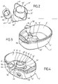
- la figure 2 montre une vue en perspective d'un support à aromates appartenant à une base de production de vapeur pour cuiseur à la vapeur selon un deuxième exemple de réalisation de l'invention,
- la figure 3 montre une vue en perspective d'une base de production de vapeur pour cuiseur à la vapeur selon le deuxième exemple de réalisation de l'invention,
- la figure 4 montre une vue en perspective de la base de production de vapeur pour cuiseur à la vapeur avec le support à aromates selon le deuxième exemple de réalisation de l'invention, un couvercle étant agencé sur une ouverture du support à aromates.
- Figure 1 shows a cross-sectional view of a first embodiment of a steam production base for steam cooker according to the invention, comprising an aromatic carrier.
- FIG. 2 shows a perspective view of an aromatics support belonging to a steamer steam production base according to a second embodiment of the invention,
- FIG. 3 shows a perspective view of a steamer steam production base according to the second embodiment of the invention,
- Figure 4 shows a perspective view of the steam cooker steam production base with the flavor carrier according to the second embodiment of the invention, a lid being arranged on an opening of the flavor carrier.
La figure 1 montre une base de production de vapeur 1 appartenant à un cuiseur vapeur. La base 1 comporte dans un boîtier 2 un réceptacle 3 prévu pour contenir de l'eau. La base 1 comprend un élément chauffant 5 électrique associé à une chambre d'ébullition 7. L'élément chauffant 5 est monté sur le fond 4 du réceptacle 3. La chambre d'ébullition 7 est alimentée par un réservoir d'eau 6. Un passage 8 relie la chambre d'ébullition 7 et le réservoir d'eau 6. Un élément séparateur 10 disposé sur le fond 4 du réceptacle 3 sépare la chambre d'ébullition 7 du réservoir d'eau 6. Le passage 8 est ménagé entre le fond de l'élément 10 et le fond 4 du réceptacle 3.Figure 1 shows a
L'élément séparateur 10 est amovible et constitue un support à aromates 11 formant un récipient 12 prévu pour recevoir un liquide aromatique ou un liquide additionné d'aromates. Le support à aromates 11 est agencé entre le réservoir d'eau 6 et la chambre d'ébullition 7. Le support à aromates 11 entoure la chambre d'ébullition 7. Le support à aromates 11 comporte des pieds 17 reposant sur le fond 4 du réceptacle 3. Les pieds 17 permettent de former le passage 8 entre le réservoir d'eau 6 et la chambre d'ébullition 7. Le récipient 12 comporte une paroi latérale intérieure annulaire 13 réalisée en matériau bon conducteur de chaleur, par exemple en aluminium, reliée par un fond à une paroi latérale extérieure annulaire 14. Le récipient 12 est annulaire et entoure la chambre d'ébullition 7.The
L'élément chauffant 5 présente un sommet 40 formant une protubérance par rapport au fond de la chambre d'ébullition 7. Le fond du récipient 12 est agencé plus bas que le sommet 40 de l'élément chauffant 5.The
Un bac récupérateur 20 est disposé sur un montant annulaire 9 du boîtier 2. Le bac récupérateur 20 est surmonté d'un support de cuisson 30 présentant un fond 31 muni de perforations 32. Le bac récupérateur 20 permet de collecter les jus issus des aliments disposés sur le support de cuisson 30. Le support de cuisson 30 est fermé par un couvercle 35. Un ou plusieurs évents 36 sont ménagés sur le couvercle 35.A
Le bac récupérateur 20 comporte une cheminée 21 présentant au moins une ouverture 22 prévue pour le passage de la vapeur issue de la chambre d'ébullition 7 ménagée autour de l'élément chauffant 5, ou issue du récipient 12. L'ouverture 22 est latérale et la cheminée 21 est fermée par un toit 23. La paroi latérale extérieure annulaire 14 du récipient 12 vient s'insérer dans la cheminée 21 lorsque le bac récupérateur 20 est disposé sur le montant annulaire 9. Le bac récupérateur 20 comporte des orifices de remplissage 24.The
Le fonctionnement de la présente invention est le suivant. L'utilisateur dispose l'élément séparateur 10 autour de l'élément chauffant 5 et remplit le réservoir 12 d'un liquide aromatique et/ou d'un liquide additionné d'aromates. L'utilisateur remplit le réservoir 6 d'eau et met en place le bac récupérateur 20 puis le support de cuisson 30. Le réservoir d'eau 6 alimente la chambre d'ébullition 7 par le passage 8. L'élément chauffant 5 s'échauffe et produit de la vapeur qui est guidée par la paroi latérale intérieure 13 du récipient 12. Le support à aromates 11 canalise la vapeur issue de la chambre d'ébullition 7 ainsi que la vapeur issue du récipient 12 vers ouverture 22 du bac récupérateur 20. La vapeur est confinée par la cheminée 21 et la paroi latérale extérieure 14 du récipient 12 et s'échappe par les ouvertures latérales 22. La paroi latérale 13 délimite partiellement la périphérie de la chambre d'ébullition 7. La vapeur échauffe la face extérieure de la paroi latérale 13. La face extérieure de la paroi latérale 13 forme un élément 15 transmettant ses calories à un autre élément 16 appartenant au récipient 12, formé par la face intérieure de la paroi latérale 13. L'utilisation de la vapeur comme moyen de transmission des calories permet de limiter la température à laquelle est exposé le récipient 12. Le liquide aromatique et /ou aromatisé peut ainsi être vaporisé sans risquer de carboniser les résidus.The operation of the present invention is as follows. The user has the
Un deuxième exemple de réalisation est illustré aux figures 2 à 4. Cet exemple de réalisation diffère de l'exemple de réalisation précédent en ce que le support à aromates 11' comporte un organe de préhension 43 et une paroi latérale extérieure annulaire 14' présentant deux becs verseurs 41, 42.A second exemplary embodiment is illustrated in FIGS. 2 to 4. This embodiment differs from the previous embodiment in that the flavor carrier 11 'comprises a gripping
Tel que montré à la figure 2, les becs verseurs 41, 42 sont agencés de part et d'autre de la paroi latérale intérieure annulaire 13'. La paroi latérale extérieure annulaire 14' est reliée par un fond à la paroi latérale intérieure annulaire 13' et forme un récipient 12' annulaire. La paroi latérale intérieure annulaire 13' est avantageusement réalisée en matériau conduisant suffisamment la chaleur, notamment en métal, par exemple en aluminium ou en acier inoxydable, les autres parties du support à aromates étant avantageusement réalisées en matériau conduisant moins la chaleur, notamment en matière plastique, de préférence sous la forme d'une pièce moulée, par exemple en polypropylène.As shown in Figure 2, the
Plus particulièrement, l'organe de préhension 43 est issu de la partie inférieure de la paroi latérale annulaire extérieure 14'. L'organe de préhension 43 comporte une partie externe 44 reliée par un montant 45 à la paroi latérale annulaire extérieure 14'. La partie externe 44 présente un passage 46 et un logement d'axe 47 agencé latéralement par rapport au passage 46. Une zone d'appui 48 est agencée entre le montant 45 et la paroi latérale extérieure 14'.More particularly, the gripping
La figure 3 montre une base de production de vapeur 1' prévue pour recevoir le support à aromates 11'. La base de production de vapeur 1' comporte un boîtier 2' formant un réceptacle 3'. Un élément chauffant 5' est agencé dans le réceptacle 3'. L'élément chauffant 5' présente un sommet 40'. Le boîtier 2' comporte un dispositif de remplissage 50 comprenant une ouverture supérieure 51 communiquant avec une ouverture inférieure 52 débouchant dans le réceptacle 3'. Une zone de réception 53 ménagée dans le fond du réceptacle 3' est prévue pour recevoir la zone d'appui 48 du support à aromates 11'.Figure 3 shows a steam production base 1 'for receiving the flavor carrier 11'. The steam production base 1 'comprises a housing 2' forming a receptacle 3 '. A heating element 5 'is arranged in the receptacle 3'. The heating element 5 'has a vertex 40'. The housing 2 'comprises a filling
Tel que montré à la figure 4, le support à aromates 11' est disposé dans le réceptacle 3' du boîtier 2' de la base de production de vapeur 1'. Le récipient 12' formé par le support à aromates 11' entoure la chambre d'ébullition 7' agencée autour de l'élément chauffant 5'. La partie externe 44 de l'organe de préhension 43 s'étend à l'extérieur du boîtier 2' lorsque le support à aromates 11' est en place dans le boîtier 2'. Le réceptacle 3' forme un réservoir d'eau 6' autour du support à aromates 11'. Un espace ménagé entre le réceptacle 3' et le support à aromates 11' permet l'alimentation de la chambre d'ébullition 7' par le réservoir d'eau 6'.As shown in Figure 4, the flavor carrier 11 'is disposed in the receptacle 3' of the housing 2 'of the steam production base 1'. The container 12 'formed by the flavor carrier 11' surrounds the boiling chamber 7 'arranged around the heating element 5'. The
Le passage 46 de la partie externe 44 est alors agencé au dessus de l'ouverture supérieure 51 du dispositif de remplissage 50. Un couvercle 55 obture le passage 46. Le couvercle 55 est monté pivotant par rapport à la partie externe 44. A cet effet, le couvercle 55 comporte un tenon prévu pour pivoter dans le logement d'axe 47. Un ergot 54 facile la rotation du couvercle 55.The
Le support à aromates 11' est amovible. La mise en place du support à aromates 11' dans le boîtier 2' et le retrait du support à aromates 11' du boîtier 2' sont particulièrement aisés grâce à l'organe de préhension 43. De plus, l'échauffement limité de l'organe de préhension 43 lors du fonctionnement de la base de production de vapeur 1' permet une manipulation sans danger.The flavor carrier 11 'is removable. The introduction of the aromatics support 11 'in the housing 2' and the removal of the aromatics support 11 'from the housing 2 'are particularly easy thanks to the gripping
Les becs verseurs 41, 42 facilitent le versement du contenu du récipient 12', mais aussi le remplissage du récipient 12', grâce à une surface de réception plus large que l'espacement entre la paroi latérale intérieure annulaire 13' et la paroi latérale extérieure annulaire 14'.The
Le remplissage du réceptacle 3' peut s'effectuer par le passage 46 et l'ouverture supérieure 51 lorsque la base de production de vapeur 1' est surmontée d'éléments de cuisson.The filling of the receptacle 3 'can be done through the
A titre de variante, le support à aromates 11' ne comporte pas nécessairement deux becs verseurs. De préférence le support à aromates 11' comporte au moins un bec verseur.Alternatively, the flavor carrier 11 'does not necessarily have two spouts. Preferably the flavor carrier 11 'has at least one spout.
A titre de variante, l'élément séparateur 10 n'entoure pas nécessairement l'élément chauffant 5. La chambre d'ébullition et le réservoir d'eau sont alors adjacents mais non concentriques. Le support à aromates 11 ; 11' ne forme pas nécessairement un élément séparateur. Le support à aromates peut alors être simplement disposé dans la chambre d'ébullition.Alternatively, the
La présente invention n'est nullement limitée à l'exemple de réalisation décrit et à ses variantes, mais englobe de nombreuses modifications dans le cadre des revendications.The present invention is not limited to the embodiment described and its variants, but encompasses many modifications within the scope of the claims.
La présente invention trouve une application dans le domaine des appareils électriques de cuisson à la vapeur, ainsi que dans le domaine des ustensiles de cuisson à la vapeur destinés à être disposés sur une source chauffante.The present invention finds application in the field of electric appliances for steam cooking, as well as in the field of steam cookware intended to be arranged on a heating source.
Claims (21)
- A steam-generator base for a steam cooker, said base including a boiler chamber (7; 7') disposed in a housing (2; 2') forming a tank (3; 3'), and a flavoring substance support (11; 11') that is removable relative to the housing (2; 2'), the flavoring substance support (11; 11') forming a receptacle (12; 12') having a side wall (13; 13'), the flow of steam coming from the boiler chamber (7; 7') heating the receptacle (12; 12'), said steam-generator base being characterized in that the receptacle (12; 12') stands on the bottom of the tank (3; 3'), and in that the side wall (13; 13') of the receptacle (12; 12') defines in part the periphery of the boiler chamber (7; 7').
- A steam-generator base according to claim 1, characterized in that it includes a heater element (5; 5') associated with the boiler chamber (7; 7').
- A steam-generator base according to claim 2, characterized in that the heater element (5) has a top (40) forming a protuberance relative to the bottom of the boiler chamber (7).
- A steam-generator base according to claim 3, characterized in that the bottom of the receptacle (12) is arranged lower than the top (40) of the heater element (5).
- A steam-generator base according to any one of claims 1 to 4, characterized in that the flavoring substance support (11) is arranged laterally relative to the boiler chamber (7).
- A steam-generator base according to any one of claims 1 to 5, characterized in that the side wall (13) is made of aluminum.
- A steam-generator base according to any one of claims 1 to 5, characterized in that the side wall (13') is made of metal.
- A steam-generator base according to any one of claims 1 to 7, characterized in that the steam-generator base includes a water reservoir (6; 6') feeding the boiler chamber (7; 7').
- A steam-generator base according to claim 8, characterized in that the flavoring substance support (11; 11') separates the water reservoir (6; 6') from the boiler chamber (7; 7').
- A steam-generator base according to claim 8 or claim 9, characterized in that the flavoring substance support (11; 11') surrounds the boiler chamber (7; 7').
- A steam-generator base according to claim 10, characterized in that the receptacle (12; 12') is annular and surrounds the boiler chamber (7; 7').
- A steam-generator base according to any one of claims 1 to 11, characterized in that the steam-generator base has an annular upright (9) on which a collector pan (20) is disposed that is provided with a steam-passing opening (22) that communicates with the boiler chamber (7).
- A steam-generator base according to claim 12, characterized in that the flavoring substance support (11) channels the steam coming from the boiler chamber (7) and the steam coming from the receptacle (12) towards the opening (22) in the collector pan (20).
- A steam-generator base according to claim 13, characterized in that the receptacle (12) has an annular outer wall (14) that becomes engaged in a chimney (21) of the collector pan (20).
- A steam-generator base according to any one of claims 1 to 14, characterized in that the flavoring substance support (11') is provided with at least one spout (41, 42).
- A steam-generator base according to any one of claims 1 to 15, characterized in that the flavoring substance support (11') is provided with a handle-forming member (43).
- A steam-generator base according to claim 16, characterized in that the handle-forming member (43) has an outer portion (44) that extends outside the housing (2') when the flavoring substance support (11') is in place in the housing (2').
- A steam-generator base according to claim 17, characterized in that the outer portion (44) is provided with a passageway (46) arranged above a top opening (51) in a filling device (50) having a bottom opening (52) that opens out in a tank (3') arranged in a housing (2').
- A steam-generator base according to claim 18, characterized in that a lid (55) mounted on the outer portion (44) is suitable for closing off the passageway (46).
- A steam-generator base according to any one of claims 1 to 19, characterized in that the flavoring substance support (11; 11') is in contact with the water present in the boiler chamber (7; 7').
- A steam-generator base according to any one of claims 1 to 20, characterized in that the receptacle (12; 12') is in contact with the water present in the boiler chamber (7; 7').
Applications Claiming Priority (5)
| Application Number | Priority Date | Filing Date | Title |
|---|---|---|---|
| FR0213253 | 2002-10-23 | ||
| FR0213253A FR2846216A1 (en) | 2002-10-23 | 2002-10-23 | Steam production base for steam cooker comprises boiling chamber located in case and aromatic support forming container heated by steam leaving boiling chamber |
| FR0307414 | 2003-06-19 | ||
| FR0307414A FR2846217B1 (en) | 2002-10-23 | 2003-06-19 | VAPOR PRODUCTION BASE FOR STEAM COOKER, HAVING AROMATIC SUPPORT |
| PCT/FR2003/003042 WO2004037055A1 (en) | 2002-10-23 | 2003-10-15 | Vapour production base for steam cooker comprising an aromatic support |
Publications (2)
| Publication Number | Publication Date |
|---|---|
| EP1555919A1 EP1555919A1 (en) | 2005-07-27 |
| EP1555919B1 true EP1555919B1 (en) | 2007-05-23 |
Family
ID=32095129
Family Applications (1)
| Application Number | Title | Priority Date | Filing Date |
|---|---|---|---|
| EP03809358A Expired - Lifetime EP1555919B1 (en) | 2002-10-23 | 2003-10-15 | Vapour production base for steam cooker comprising an aromatic support |
Country Status (6)
| Country | Link |
|---|---|
| EP (1) | EP1555919B1 (en) |
| AT (1) | ATE362723T1 (en) |
| AU (1) | AU2003301649A1 (en) |
| DE (1) | DE60313997T2 (en) |
| FR (1) | FR2846217B1 (en) |
| WO (1) | WO2004037055A1 (en) |
Families Citing this family (11)
| Publication number | Priority date | Publication date | Assignee | Title |
|---|---|---|---|---|
| US7312424B2 (en) * | 2004-04-05 | 2007-12-25 | Hannon Todd J | Apparatus and a method for cooking garlic |
| DE602004003227T2 (en) * | 2004-06-11 | 2007-09-20 | Wen-Ching Li | Steam cooker |
| FR2896976B1 (en) * | 2006-02-03 | 2008-03-14 | Seb Sa | COOKING ACCESSORY FOR STEAM COOKING DEVICE |
| FR2980348B1 (en) * | 2011-09-28 | 2013-10-11 | Seb Sa | STEAM COOKER WITH FILLING DEVICE FOR WATER TANK DURING COOKING |
| FR3014664B1 (en) * | 2013-12-13 | 2016-02-05 | Seb Sa | ELECTRICAL HEATING AND / OR COOKING APPARATUS FOR STEAM FOOD |
| FR3014665B1 (en) * | 2013-12-13 | 2016-02-05 | Seb Sa | METHOD AND APPARATUS FOR HEATING AND / OR COOKING STEAM FOOD |
| FR3089401B1 (en) * | 2018-12-07 | 2021-01-08 | Seb Sa | STEAM COOKER ACCESSORY WITH OFFSET STEAM DUCT |
| FR3089399B1 (en) * | 2018-12-07 | 2021-01-08 | Seb Sa | STEAM COOKER ACCESSORY WITH REMOVABLE CAP |
| FR3089396B1 (en) * | 2018-12-07 | 2022-01-14 | Seb Sa | STEAMER ATTACHMENT WITH SUPPORT DEVICE PROVIDED WITH RIBS |
| FR3089397B1 (en) * | 2018-12-07 | 2020-11-13 | Seb Sa | STEAM COOKER ACCESSORY WITH DOUBLE TURBO CROWN |
| DE102019220291A1 (en) * | 2019-12-19 | 2021-06-24 | BSH Hausgeräte GmbH | Evaporation device and domestic cooking appliance |
Family Cites Families (7)
| Publication number | Priority date | Publication date | Assignee | Title |
|---|---|---|---|---|
| US448886A (en) * | 1891-03-24 | Apparatus for baking | ||
| US3078783A (en) * | 1960-11-21 | 1963-02-26 | Sr Maurice W Lee | Aromatic pressure cooker |
| US5363748A (en) * | 1993-01-15 | 1994-11-15 | Tsann Kuen Usa, Inc. | Electrical cooker |
| US5275094A (en) * | 1993-05-17 | 1994-01-04 | Black & Decker Inc. | Divider basket for steam cooking utensil |
| US5653161A (en) * | 1995-12-18 | 1997-08-05 | Black & Decker Inc. | Food steamer with pressure venting |
| US5794525A (en) * | 1997-11-12 | 1998-08-18 | Fan; Chi-Po | Cooking device |
| US5988045A (en) * | 1998-09-30 | 1999-11-23 | Housley; Todd B. | Utensil supporting multiple cooking environments for preparing foods |
-
2003
- 2003-06-19 FR FR0307414A patent/FR2846217B1/en not_active Expired - Fee Related
- 2003-10-15 DE DE60313997T patent/DE60313997T2/en not_active Expired - Lifetime
- 2003-10-15 WO PCT/FR2003/003042 patent/WO2004037055A1/en active IP Right Grant
- 2003-10-15 AU AU2003301649A patent/AU2003301649A1/en not_active Abandoned
- 2003-10-15 AT AT03809358T patent/ATE362723T1/en not_active IP Right Cessation
- 2003-10-15 EP EP03809358A patent/EP1555919B1/en not_active Expired - Lifetime
Also Published As
| Publication number | Publication date |
|---|---|
| ATE362723T1 (en) | 2007-06-15 |
| FR2846217B1 (en) | 2006-07-21 |
| FR2846217A1 (en) | 2004-04-30 |
| AU2003301649A1 (en) | 2004-05-13 |
| DE60313997D1 (en) | 2007-07-05 |
| EP1555919A1 (en) | 2005-07-27 |
| WO2004037055A1 (en) | 2004-05-06 |
| DE60313997T2 (en) | 2008-01-24 |
Similar Documents
| Publication | Publication Date | Title |
|---|---|---|
| EP3079530B1 (en) | Electrical appliance for the steam-heating and/or -cooking of food | |
| EP1049396B1 (en) | Steamer with lateral water fill | |
| EP2433525B1 (en) | Steam cooker-mixer | |
| EP3558071B1 (en) | Modular steamer accessory for steam-heating and/or -cooking food contained in a container | |
| EP3079529B1 (en) | Method and appliance for heating and/or cooking foods with steam | |
| EP3087879B1 (en) | Steam-cooking accessory comprising a pan for recovering condensates intended for resting on a mixing bowl of a household appliance | |
| EP1555919B1 (en) | Vapour production base for steam cooker comprising an aromatic support | |
| EP1308114B1 (en) | Multifunctional steam-cooker with improved autonomy | |
| EP1343401B1 (en) | Utensil for slow-cook cycle steaming | |
| EP2536316B1 (en) | Basket for an electrical appliance for steam-heating food or for a cooking utensil | |
| EP3424378A1 (en) | Internal receptacle, food preparation accessory and kitchen appliance including such an internal receptacle | |
| EP2071985B1 (en) | Steam cooker with refilling system | |
| FR2846216A1 (en) | Steam production base for steam cooker comprises boiling chamber located in case and aromatic support forming container heated by steam leaving boiling chamber | |
| WO2007009195A1 (en) | Cooking appliance | |
| EP1795096B1 (en) | Cooking device | |
| EP1736083A1 (en) | Cooker with anti-foaming device | |
| FR2818523A1 (en) | Utensil for slow steam cooking | |
| EP1978850B1 (en) | Cooking accessory for a steam cooking device | |
| FR2846215A1 (en) | Food steamer has perforated support with apertures for series of separate containers for simultaneous steaming | |
| WO2000047092A1 (en) | Specialised cooking element for steam cooker |
Legal Events
| Date | Code | Title | Description |
|---|---|---|---|
| PUAI | Public reference made under article 153(3) epc to a published international application that has entered the european phase |
Free format text: ORIGINAL CODE: 0009012 |
|
| 17P | Request for examination filed |
Effective date: 20050421 |
|
| AK | Designated contracting states |
Kind code of ref document: A1 Designated state(s): AT BE BG CH CY CZ DE DK EE ES FI FR GB GR HU IE IT LI LU MC NL PT RO SE SI SK TR |
|
| AX | Request for extension of the european patent |
Extension state: AL LT LV MK |
|
| DAX | Request for extension of the european patent (deleted) | ||
| GRAP | Despatch of communication of intention to grant a patent |
Free format text: ORIGINAL CODE: EPIDOSNIGR1 |
|
| GRAS | Grant fee paid |
Free format text: ORIGINAL CODE: EPIDOSNIGR3 |
|
| GRAA | (expected) grant |
Free format text: ORIGINAL CODE: 0009210 |
|
| AK | Designated contracting states |
Kind code of ref document: B1 Designated state(s): AT BE BG CH CY CZ DE DK EE ES FI FR GB GR HU IE IT LI LU MC NL PT RO SE SI SK TR |
|
| PG25 | Lapsed in a contracting state [announced via postgrant information from national office to epo] |
Ref country code: FI Free format text: LAPSE BECAUSE OF FAILURE TO SUBMIT A TRANSLATION OF THE DESCRIPTION OR TO PAY THE FEE WITHIN THE PRESCRIBED TIME-LIMIT Effective date: 20070523 |
|
| REG | Reference to a national code |
Ref country code: GB Ref legal event code: FG4D Free format text: NOT ENGLISH |
|
| REG | Reference to a national code |
Ref country code: CH Ref legal event code: EP |
|
| REG | Reference to a national code |
Ref country code: IE Ref legal event code: FG4D Free format text: LANGUAGE OF EP DOCUMENT: FRENCH |
|
| REF | Corresponds to: |
Ref document number: 60313997 Country of ref document: DE Date of ref document: 20070705 Kind code of ref document: P |
|
| GBT | Gb: translation of ep patent filed (gb section 77(6)(a)/1977) |
Effective date: 20070725 |
|
| PG25 | Lapsed in a contracting state [announced via postgrant information from national office to epo] |
Ref country code: SE Free format text: LAPSE BECAUSE OF FAILURE TO SUBMIT A TRANSLATION OF THE DESCRIPTION OR TO PAY THE FEE WITHIN THE PRESCRIBED TIME-LIMIT Effective date: 20070823 |
|
| PG25 | Lapsed in a contracting state [announced via postgrant information from national office to epo] |
Ref country code: ES Free format text: LAPSE BECAUSE OF FAILURE TO SUBMIT A TRANSLATION OF THE DESCRIPTION OR TO PAY THE FEE WITHIN THE PRESCRIBED TIME-LIMIT Effective date: 20070903 |
|
| NLV1 | Nl: lapsed or annulled due to failure to fulfill the requirements of art. 29p and 29m of the patents act | ||
| PG25 | Lapsed in a contracting state [announced via postgrant information from national office to epo] |
Ref country code: AT Free format text: LAPSE BECAUSE OF FAILURE TO SUBMIT A TRANSLATION OF THE DESCRIPTION OR TO PAY THE FEE WITHIN THE PRESCRIBED TIME-LIMIT Effective date: 20070523 |
|
| REG | Reference to a national code |
Ref country code: IE Ref legal event code: FD4D |
|
| PG25 | Lapsed in a contracting state [announced via postgrant information from national office to epo] |
Ref country code: NL Free format text: LAPSE BECAUSE OF FAILURE TO SUBMIT A TRANSLATION OF THE DESCRIPTION OR TO PAY THE FEE WITHIN THE PRESCRIBED TIME-LIMIT Effective date: 20070523 Ref country code: SI Free format text: LAPSE BECAUSE OF FAILURE TO SUBMIT A TRANSLATION OF THE DESCRIPTION OR TO PAY THE FEE WITHIN THE PRESCRIBED TIME-LIMIT Effective date: 20070523 Ref country code: CZ Free format text: LAPSE BECAUSE OF FAILURE TO SUBMIT A TRANSLATION OF THE DESCRIPTION OR TO PAY THE FEE WITHIN THE PRESCRIBED TIME-LIMIT Effective date: 20070523 Ref country code: DK Free format text: LAPSE BECAUSE OF FAILURE TO SUBMIT A TRANSLATION OF THE DESCRIPTION OR TO PAY THE FEE WITHIN THE PRESCRIBED TIME-LIMIT Effective date: 20070523 Ref country code: IE Free format text: LAPSE BECAUSE OF FAILURE TO SUBMIT A TRANSLATION OF THE DESCRIPTION OR TO PAY THE FEE WITHIN THE PRESCRIBED TIME-LIMIT Effective date: 20070523 Ref country code: PT Free format text: LAPSE BECAUSE OF FAILURE TO SUBMIT A TRANSLATION OF THE DESCRIPTION OR TO PAY THE FEE WITHIN THE PRESCRIBED TIME-LIMIT Effective date: 20071023 Ref country code: BG Free format text: LAPSE BECAUSE OF FAILURE TO SUBMIT A TRANSLATION OF THE DESCRIPTION OR TO PAY THE FEE WITHIN THE PRESCRIBED TIME-LIMIT Effective date: 20070823 |
|
| PG25 | Lapsed in a contracting state [announced via postgrant information from national office to epo] |
Ref country code: SK Free format text: LAPSE BECAUSE OF FAILURE TO SUBMIT A TRANSLATION OF THE DESCRIPTION OR TO PAY THE FEE WITHIN THE PRESCRIBED TIME-LIMIT Effective date: 20070523 |
|
| PLBE | No opposition filed within time limit |
Free format text: ORIGINAL CODE: 0009261 |
|
| STAA | Information on the status of an ep patent application or granted ep patent |
Free format text: STATUS: NO OPPOSITION FILED WITHIN TIME LIMIT |
|
| 26N | No opposition filed |
Effective date: 20080226 |
|
| BERE | Be: lapsed |
Owner name: SEB S.A. Effective date: 20071031 |
|
| PG25 | Lapsed in a contracting state [announced via postgrant information from national office to epo] |
Ref country code: IT Free format text: LAPSE BECAUSE OF FAILURE TO SUBMIT A TRANSLATION OF THE DESCRIPTION OR TO PAY THE FEE WITHIN THE PRESCRIBED TIME-LIMIT Effective date: 20070523 Ref country code: GR Free format text: LAPSE BECAUSE OF FAILURE TO SUBMIT A TRANSLATION OF THE DESCRIPTION OR TO PAY THE FEE WITHIN THE PRESCRIBED TIME-LIMIT Effective date: 20070824 |
|
| PG25 | Lapsed in a contracting state [announced via postgrant information from national office to epo] |
Ref country code: MC Free format text: LAPSE BECAUSE OF NON-PAYMENT OF DUE FEES Effective date: 20071031 Ref country code: RO Free format text: LAPSE BECAUSE OF FAILURE TO SUBMIT A TRANSLATION OF THE DESCRIPTION OR TO PAY THE FEE WITHIN THE PRESCRIBED TIME-LIMIT Effective date: 20070523 |
|
| REG | Reference to a national code |
Ref country code: CH Ref legal event code: PL |
|
| PG25 | Lapsed in a contracting state [announced via postgrant information from national office to epo] |
Ref country code: CH Free format text: LAPSE BECAUSE OF NON-PAYMENT OF DUE FEES Effective date: 20071031 Ref country code: LI Free format text: LAPSE BECAUSE OF NON-PAYMENT OF DUE FEES Effective date: 20071031 |
|
| PG25 | Lapsed in a contracting state [announced via postgrant information from national office to epo] |
Ref country code: BE Free format text: LAPSE BECAUSE OF NON-PAYMENT OF DUE FEES Effective date: 20071031 |
|
| PG25 | Lapsed in a contracting state [announced via postgrant information from national office to epo] |
Ref country code: EE Free format text: LAPSE BECAUSE OF FAILURE TO SUBMIT A TRANSLATION OF THE DESCRIPTION OR TO PAY THE FEE WITHIN THE PRESCRIBED TIME-LIMIT Effective date: 20070523 |
|
| PG25 | Lapsed in a contracting state [announced via postgrant information from national office to epo] |
Ref country code: CY Free format text: LAPSE BECAUSE OF FAILURE TO SUBMIT A TRANSLATION OF THE DESCRIPTION OR TO PAY THE FEE WITHIN THE PRESCRIBED TIME-LIMIT Effective date: 20070523 |
|
| PG25 | Lapsed in a contracting state [announced via postgrant information from national office to epo] |
Ref country code: LU Free format text: LAPSE BECAUSE OF NON-PAYMENT OF DUE FEES Effective date: 20071015 |
|
| PG25 | Lapsed in a contracting state [announced via postgrant information from national office to epo] |
Ref country code: TR Free format text: LAPSE BECAUSE OF FAILURE TO SUBMIT A TRANSLATION OF THE DESCRIPTION OR TO PAY THE FEE WITHIN THE PRESCRIBED TIME-LIMIT Effective date: 20070523 Ref country code: HU Free format text: LAPSE BECAUSE OF FAILURE TO SUBMIT A TRANSLATION OF THE DESCRIPTION OR TO PAY THE FEE WITHIN THE PRESCRIBED TIME-LIMIT Effective date: 20071124 |
|
| PGFP | Annual fee paid to national office [announced via postgrant information from national office to epo] |
Ref country code: GB Payment date: 20090924 Year of fee payment: 7 |
|
| PGFP | Annual fee paid to national office [announced via postgrant information from national office to epo] |
Ref country code: DE Payment date: 20091016 Year of fee payment: 7 |
|
| GBPC | Gb: european patent ceased through non-payment of renewal fee |
Effective date: 20101015 |
|
| PG25 | Lapsed in a contracting state [announced via postgrant information from national office to epo] |
Ref country code: GB Free format text: LAPSE BECAUSE OF NON-PAYMENT OF DUE FEES Effective date: 20101015 |
|
| REG | Reference to a national code |
Ref country code: DE Ref legal event code: R119 Ref document number: 60313997 Country of ref document: DE Effective date: 20110502 |
|
| PG25 | Lapsed in a contracting state [announced via postgrant information from national office to epo] |
Ref country code: DE Free format text: LAPSE BECAUSE OF NON-PAYMENT OF DUE FEES Effective date: 20110502 |
|
| REG | Reference to a national code |
Ref country code: FR Ref legal event code: PLFP Year of fee payment: 13 |
|
| PGFP | Annual fee paid to national office [announced via postgrant information from national office to epo] |
Ref country code: FR Payment date: 20151102 Year of fee payment: 13 |
|
| REG | Reference to a national code |
Ref country code: FR Ref legal event code: ST Effective date: 20170630 |
|
| PG25 | Lapsed in a contracting state [announced via postgrant information from national office to epo] |
Ref country code: FR Free format text: LAPSE BECAUSE OF NON-PAYMENT OF DUE FEES Effective date: 20161102 |