EP1555919B1 - Dampfherstellungsbasis für einen dampfkocher mit einem aromastoffträger - Google Patents
Dampfherstellungsbasis für einen dampfkocher mit einem aromastoffträger Download PDFInfo
- Publication number
- EP1555919B1 EP1555919B1 EP03809358A EP03809358A EP1555919B1 EP 1555919 B1 EP1555919 B1 EP 1555919B1 EP 03809358 A EP03809358 A EP 03809358A EP 03809358 A EP03809358 A EP 03809358A EP 1555919 B1 EP1555919 B1 EP 1555919B1
- Authority
- EP
- European Patent Office
- Prior art keywords
- steam
- generator base
- base according
- receptacle
- boiler chamber
- Prior art date
- Legal status (The legal status is an assumption and is not a legal conclusion. Google has not performed a legal analysis and makes no representation as to the accuracy of the status listed.)
- Expired - Lifetime
Links
- 125000003118 aryl group Chemical group 0.000 title abstract description 29
- 238000004519 manufacturing process Methods 0.000 title abstract description 29
- 238000010438 heat treatment Methods 0.000 claims description 23
- XLYOFNOQVPJJNP-UHFFFAOYSA-N water Substances O XLYOFNOQVPJJNP-UHFFFAOYSA-N 0.000 claims description 21
- 229910052782 aluminium Inorganic materials 0.000 claims description 4
- XAGFODPZIPBFFR-UHFFFAOYSA-N aluminium Chemical compound [Al] XAGFODPZIPBFFR-UHFFFAOYSA-N 0.000 claims description 4
- 229910052751 metal Inorganic materials 0.000 claims description 2
- 239000002184 metal Substances 0.000 claims description 2
- 239000000126 substance Substances 0.000 claims 10
- 238000009835 boiling Methods 0.000 abstract description 32
- 239000000796 flavoring agent Substances 0.000 description 19
- 235000019634 flavors Nutrition 0.000 description 19
- 238000010411 cooking Methods 0.000 description 12
- 238000011084 recovery Methods 0.000 description 9
- 239000007788 liquid Substances 0.000 description 8
- 239000004020 conductor Substances 0.000 description 4
- 235000011389 fruit/vegetable juice Nutrition 0.000 description 4
- 238000004140 cleaning Methods 0.000 description 2
- 239000004743 Polypropylene Substances 0.000 description 1
- 238000005899 aromatization reaction Methods 0.000 description 1
- 238000005485 electric heating Methods 0.000 description 1
- 239000000463 material Substances 0.000 description 1
- 238000012986 modification Methods 0.000 description 1
- 230000004048 modification Effects 0.000 description 1
- 239000004033 plastic Substances 0.000 description 1
- -1 polypropylene Polymers 0.000 description 1
- 229920001155 polypropylene Polymers 0.000 description 1
- 230000000284 resting effect Effects 0.000 description 1
- 229910001220 stainless steel Inorganic materials 0.000 description 1
- 239000010935 stainless steel Substances 0.000 description 1
Images

Classifications
-
- A—HUMAN NECESSITIES
- A47—FURNITURE; DOMESTIC ARTICLES OR APPLIANCES; COFFEE MILLS; SPICE MILLS; SUCTION CLEANERS IN GENERAL
- A47J—KITCHEN EQUIPMENT; COFFEE MILLS; SPICE MILLS; APPARATUS FOR MAKING BEVERAGES
- A47J27/00—Cooking-vessels
- A47J27/04—Cooking-vessels for cooking food in steam; Devices for extracting fruit juice by means of steam ; Vacuum cooking vessels
Definitions
- the present invention relates to the technical field of steam cooking apparatus.
- the steam cookers comprise one or more cooking vessels arranged on a steam production base.
- the containers have a perforated bottom allowing the steam to rise by passing around the food arranged on the perforated bottom.
- the steam production base may or may not have a means for autonomous heating of the water.
- the object of the present invention is to provide a steam production base for a steam cooker, intended for the use of aromatics, wherein the cleaning related to the use of aromatics is simplified.
- Another object of the present invention is to provide a steam production base for a steam cooker, intended for the use of aromatic liquids.
- the aromatic support thus makes it possible to receive aromatic liquids. Heating by steam limits the temperatures reached by the container and its contents.
- the steam production base comprises a heating element associated with the boiling chamber.
- the heating element has an apex forming a protuberance with respect to the bottom of the boiling chamber.
- Other embodiments are possible, such as a heating base or a tubular boiler.
- the bottom of the container is arranged lower than the top of the heating element.
- this arrangement makes it possible to limit the height of the steam production base.
- the aromatic support is arranged laterally with respect to the boiling chamber. This arrangement makes it possible to obtain a stream of aromatic vapors parallel to the vapor coming from the boiling chamber.
- an element made of a good heat conducting material, for example aluminum, arranged in or around the boiling chamber, is thermally connected to another element made in good heat conducting material, belonging to the container.
- these two elements are formed by a side wall of the container partially defining the periphery of the boiling chamber.
- the steam production base comprises a water tank supplying the boiling chamber.
- the amount of water brought to the boil can be reduced, which allows a faster production of steam while maintaining a significant cooking autonomy thanks to the water tank.
- the aromatic support separates the water tank from the boiling chamber.
- the flavor carrier can thus replace the wall separating the water tank from the boiling chamber.
- the aromatic support surrounds the boiling chamber.
- the aromatic support forms a crown.
- the container of the aromatic support is annular and surrounds the boiling chamber. This arrangement makes it easier to heat the container.
- the steam production base comprises an annular upright on which is disposed a recovery tank having a steam passage opening communicating with the boiling chamber.
- the aromatic support channel the steam from the boiling chamber and the steam from the container to the opening of the recovery tank. This arrangement allows to direct the steam to the cooking vessel by limiting losses.
- the container of the aromatic support has an annular outer wall that fits into a stack of the recovery tank.
- the aromatic support is removable.
- the aromatic support comprises at least one spout. This arrangement facilitates the filling as well as the pouring of the contents of the aromatic support.
- the aromatic support comprises a gripping member. This arrangement facilitates the handling of the aromatic support, which is heated during cooking.
- the gripping member has an outer portion extending outside the housing when the flavor carrier is in place in the housing. This arrangement makes it possible to indicate the presence of the aromatic support in the steam production base.
- the outer portion has a passage arranged above an upper opening of a filling device having a lower opening opening into a receptacle arranged in the housing.
- a lid mounted on the outer portion is likely to close the passage.
- FIG. 1 shows a steam production base 1 belonging to a steam cooker.
- the base 1 comprises in a housing 2 a receptacle 3 designed to contain water.
- the base 1 comprises an electric heating element 5 associated with a boiling chamber 7.
- the heating element 5 is mounted on the bottom 4 of the receptacle 3.
- the boiling chamber 7 is fed by a water tank 6.
- a passage 8 connects the boiling chamber 7 and the water tank 6.
- a separating element 10 disposed on the bottom 4 of the receptacle 3 separates the chamber boiling water tank 7.
- the passage 8 is formed between the bottom of the element 10 and the bottom 4 of the receptacle 3.
- the separator element 10 is removable and is an aromatic carrier 11 forming a container 12 provided to receive an aromatic liquid or a liquid supplemented with aromatics.
- the flavor carrier 11 is arranged between the water reservoir 6 and the boiling chamber 7.
- the flavor carrier 11 surrounds the boiling chamber 7.
- the flavor carrier 11 has feet 17 resting on the bottom 4 of the receptacle 3. The feet 17 make it possible to form the passage 8 between the water tank 6 and the boiling chamber 7.
- the receptacle 12 has an annular inner lateral wall 13 made of a good heat-conducting material, for example made of aluminum, connected by a bottom to an annular outer side wall 14.
- the container 12 is annular and surrounds the boiling chamber 7.
- the heating element 5 has an apex 40 forming a protuberance with respect to the bottom of the boiling chamber 7.
- the bottom of the container 12 is arranged lower than the top 40 of the heating element 5.
- a recovery tank 20 is disposed on an annular upright 9 of the housing 2.
- the recovery tank 20 is surmounted by a cooking support 30 having a bottom 31 provided with perforations 32.
- the recovery tank 20 makes it possible to collect the juices from the arranged foodstuffs. on the cooking support 30.
- the cooking support 30 is closed by a lid 35.
- One or more vents 36 are formed on the lid 35.
- the recovery tank 20 comprises a chimney 21 having at least one opening 22 provided for the passage of steam from the boiling chamber 7 formed around the heating element 5, or from the container 12.
- the opening 22 is lateral and the chimney 21 is closed by a roof 23.
- the annular outer lateral wall 14 of the receptacle 12 is inserted into the chimney 21 when the collecting tank 20 is placed on the annular upright 9.
- the collecting tank 20 comprises filling orifices 24.
- the operation of the present invention is as follows.
- the user has the separator element 10 around the heating element 5 and fills the reservoir 12 with an aromatic liquid and / or a liquid supplemented with aromatics.
- the user fills the tank 6 with water and sets up the recovery tank 20 and the cooking support 30.
- the water tank 6 feeds the boiling chamber 7 through the passage 8.
- the heating element 5 s' is heated and produces steam which is guided by the inner side wall 13 of the container 12.
- the flavor carrier 11 channels the steam from the boiling chamber 7 and the steam from the container 12 to the opening 22 of the recovery tank 20
- the vapor is confined by the stack 21 and the outer side wall 14 of the container 12 and escapes through the side openings 22.
- the side wall 13 partially delimits the periphery of the boiling chamber 7.
- the steam heats the outer face of the side wall 13.
- the outer face of the side wall 13 forms an element 15 transmitting its calories to another element 16 belonging to the container 12, formed by the inner face of the side wall 13
- the use of steam as a means of transmitting calories makes it possible to limit the temperature at which the container 12 is exposed.
- the aromatic and / or flavored liquid can thus be vaporized without the risk of charring the residues.
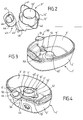
- FIGS. 2 to 4 A second exemplary embodiment is illustrated in FIGS. 2 to 4. This embodiment differs from the previous embodiment in that the flavor carrier 11 'comprises a gripping member 43 and an annular outer side wall 14' having two spouts 41, 42.
- the spouts 41, 42 are arranged on either side of the annular inner side wall 13 '.
- the annular outer side wall 14 ' is connected by a bottom to the annular inner side wall 13' and forms an annular container 12 '.
- the annular inner side wall 13 ' is advantageously made of a sufficiently heat-conducting material, in particular of metal, for example aluminum or stainless steel, the other parts of the aromatic support being advantageously made of material which leads to less heat, especially plastic, preferably in the form of a molded part, for example polypropylene.
- the gripping member 43 is derived from the lower part of the outer annular side wall 14 '.
- the gripping member 43 has an outer portion 44 connected by a post 45 to the outer annular side wall 14 '.
- the outer portion 44 has a passage 46 and an axis housing 47 arranged laterally with respect to the passage 46.
- a bearing zone 48 is arranged between the upright 45 and the outer side wall 14 '.
- FIG. 3 shows a steam production base 1 'for receiving the flavor carrier 11'.
- the steam production base 1 comprises a housing 2' forming a receptacle 3 '.
- a heating element 5 ' is arranged in the receptacle 3'.
- the heating element 5 ' has a vertex 40'.
- the housing 2 ' comprises a filling device 50 comprising an upper opening 51 communicating with a lower opening 52 opening into the receptacle 3'.
- a receiving zone 53 formed in the bottom of the receptacle 3 ' is provided to receive the support zone 48 of the flavor carrier 11'.
- the flavor carrier 11 ' is disposed in the receptacle 3' of the housing 2 'of the steam production base 1'.
- the container 12 'formed by the flavor carrier 11' surrounds the boiling chamber 7 'arranged around the heating element 5'.
- the outer portion 44 of the gripping member 43 extends outside the housing 2 'when the flavor carrier 11' is in place in the housing 2 '.
- the receptacle 3 ' forms a water tank 6' around the aromatic support 11 '. A space between the receptacle 3 'and the aromatics support 11' allows the supply of the boiling chamber 7 'by the water tank 6'.
- the passage 46 of the outer portion 44 is then arranged above the upper opening 51 of the filling device 50.
- a cover 55 closes the passage 46.
- the cover 55 is pivotally mounted relative to the outer portion 44.
- the cover 55 has a pin adapted to pivot in the pin housing 47.
- a pin 54 easy rotation of the cover 55.
- the flavor carrier 11 ' is removable.
- the limited heating of the gripping member 43 during operation of the steam production base 1' allows safe handling.
- the spouts 41, 42 facilitate the pouring of the contents of the container 12 ', but also the filling of the container 12', thanks to a receiving surface wider than the spacing between the annular inner side wall 13 'and the outer side wall ring 14 '.
- the filling of the receptacle 3 ' can be done through the passage 46 and the upper opening 51 when the steam production base 1' is surmounted by cooking elements.
- the flavor carrier 11 'does not necessarily have two spouts.
- the flavor carrier 11 ' has at least one spout.
- the separator element 10 does not necessarily surround the heating element 5.
- the boiling chamber and the water reservoir are then adjacent but not concentric.
- the flavor carrier can then simply be placed in the boiling chamber.
- the present invention finds application in the field of electric appliances for steam cooking, as well as in the field of steam cookware intended to be arranged on a heating source.
Landscapes
- Engineering & Computer Science (AREA)
- Food Science & Technology (AREA)
- Cookers (AREA)
- Macromolecular Compounds Obtained By Forming Nitrogen-Containing Linkages In General (AREA)
- Air Humidification (AREA)
- General Preparation And Processing Of Foods (AREA)
Claims (21)
- Dampferzeugungssockel für einen Dampfkocher, mit einer Siedekammer (7; 7'), die in einem Gehäuse (2; 2') angeordnet ist, das einen Auffang (3; 3') bildet, und mit einem Gewürzträger (11; 11'), der bezüglich des Gehäuses (2; 2') abnehmbar ist, wobei der Gewürzträger (11; 11') ein Gefäß (12; 12') mit einer Seitenwand (13; 13') bildet, wobei der Dampfstrom aus der Siedekammer (7; 7') das Gefäß (12; 12') erwärmt, dadurch gekennzeichnet, dass das Gefäß (12; 12') auf dem Boden des Auffangs (3; 3') aufliegt und die Seitenwand (13; 13') des Gefäßes (12; 12') den Umfang der Siedekammer (7; 7') teilweise begrenzt.
- Dampferzeugungssockel nach Anspruch 1, dadurch gekennzeichnet, dass er ein der Siedekammer (7; 7') zugeordnetes Heizelement (5, 5') aufweist.
- Dampferzeugungssockel nach Anspruch 2, dadurch gekennzeichnet, dass das Heizelement (5) einen Kopf (40) aufweist, der bezüglich des Bodens der Siedekammer (7) einen Vorsprung bildet.
- Dampferzeugungssockel nach Anspruch 3, dadurch gekennzeichnet, dass der Boden des Gefäßes (12) tiefer angeordnet ist als der Kopf (40) des Heizelements (5).
- Dampferzeugungssockel nach einem der Ansprüche 1 bis 4, dadurch gekennzeichnet, dass der Gewürzträger (11) bezüglich der Siedekammer (7) seitlich angeordnet ist.
- Dampferzeugungssockel nach einem der Ansprüche 1 bis 5, dadurch gekennzeichnet, dass die Seitenwand (13) aus Aluminium hergestellt ist.
- Dampferzeugungssockel nach einem der Ansprüche 1 bis 5, dadurch gekennzeichnet, dass die Seitenwand (13') aus Metall hergestellt ist.
- Dampferzeugungssockel nach einem der Ansprüche 1 bis 7, dadurch gekennzeichnet, dass der Dampferzeugungssockel einen Wasserbehälter aufweist (6; 6'), der die Siedekammer (7; 7') speist.
- Dampferzeugungssockel nach Anspruch 8, dadurch gekennzeichnet, dass der Gewürzträger (11; 11') den Wasserbehälter (6; 6') von der Siedekammer (7; 7') trennt.
- Dampferzeugungssockel nach Anspruch 8 oder 9, dadurch gekennzeichnet, dass der Gewürzträger (11; 11') die Siedekammer (7; 7') umgibt.
- Dampfererzeugungssockel nach Anspruch 10, dadurch gekennzeichnet, dass das Gefäß (12; 12') ringförmig ist und die Siedekammer (7; 7') umgibt.
- Dampferzeugungssockel nach einem der Ansprüche 1 bis 11, dadurch gekennzeichnet, dass der Dampferzeugungssockel eine ringförmige Strebe (9) aufweist, an der ein Sammelbehälter (20) mit einer mit der Siedekammer (7) verbundenen Dampfdurchlassöffnung (22) angeordnet ist.
- Dampferzeugungssockel nach Anspruch 12, dadurch gekennzeichnet, dass der Gewürzträger (11) den Dampf aus der Siedekammer (7) und den Dampf aus dem Gefäß (12) zur Öffnung (22) des Sammelbehälters (20) kanalisiert.
- Dampferzeugungssockel nach Anspruch 13, dadurch gekennzeichnet, dass das Gefäß (12) eine ringförmige Außenwand (14) aufweist, die in einen Schacht (21) des Sammelbehälters (20) eingesetzt ist.
- Dampferzeugungssockel nach einem der Ansprüche 1 bis 14, dadurch gekennzeichnet, dass der Gewürzträger (11') mindestens eine Tülle (41, 42) aufweist.
- Dampferzeugungssockel nach einem der Ansprüche 1 bis 15, dadurch gekennzeichnet, dass der Gewürzträger (11') ein Greiforgan (43) aufweist.
- Dampferzeugungssockel nach Anspruch 16, dadurch gekennzeichnet, dass das Greiforgan (43) einen äußeren Teil (44) aufweist, der sich außerhalb des Gehäuses (2') erstreckt, wenn der Gewürzträger (11') im Gehäuse (2') angeordnet ist.
- Dampferzeugungssockel nach Anspruch 17, dadurch gekennzeichnet, dass der äußere Teil (44) einen Durchgang (46) aufweist, der über einer oberen Öffnung (51) einer Füllvorrichtung (50) angeordnet ist, welche eine untere Öffnung (52) aufweist, die in einen im Gehäuse (2') angeordneten Auffang (3') mündet.
- Dampferzeugungssockel nach Anspruch 18, dadurch gekennzeichnet, dass ein am äußeren Teil (44) angebrachter Deckel (55) den Durchgang (46) verschließen kann.
- Dampferzeugungssockel nach einem der Ansprüche 1 bis 19, dadurch gekennzeichnet, dass der Gewürzträger (11; 11') mit dem in der Siedekammer (7; 7') vorhandenen Wasser in Kontakt ist.
- Dampferzeugungssockel nach einem der Ansprüche 1 bis 20, dadurch gekennzeichnet, dass das Gefäß (12; 12') mit dem in der Siedekammer (7; 7') vorhandenen Wasser in Kontakt ist.
Applications Claiming Priority (5)
| Application Number | Priority Date | Filing Date | Title |
|---|---|---|---|
| FR0213253 | 2002-10-23 | ||
| FR0213253A FR2846216A1 (fr) | 2002-10-23 | 2002-10-23 | Base de production de vapeur pour cuiseur vapeur, comportant un support a aromates |
| FR0307414 | 2003-06-19 | ||
| FR0307414A FR2846217B1 (fr) | 2002-10-23 | 2003-06-19 | Base de production de vapeur pour cuiseur vapeur, comportant un support a aromates |
| PCT/FR2003/003042 WO2004037055A1 (fr) | 2002-10-23 | 2003-10-15 | Base de production de vapeur pour cuiseur vapeur comportant un support a aromates |
Publications (2)
| Publication Number | Publication Date |
|---|---|
| EP1555919A1 EP1555919A1 (de) | 2005-07-27 |
| EP1555919B1 true EP1555919B1 (de) | 2007-05-23 |
Family
ID=32095129
Family Applications (1)
| Application Number | Title | Priority Date | Filing Date |
|---|---|---|---|
| EP03809358A Expired - Lifetime EP1555919B1 (de) | 2002-10-23 | 2003-10-15 | Dampfherstellungsbasis für einen dampfkocher mit einem aromastoffträger |
Country Status (6)
| Country | Link |
|---|---|
| EP (1) | EP1555919B1 (de) |
| AT (1) | ATE362723T1 (de) |
| AU (1) | AU2003301649A1 (de) |
| DE (1) | DE60313997T2 (de) |
| FR (1) | FR2846217B1 (de) |
| WO (1) | WO2004037055A1 (de) |
Families Citing this family (11)
| Publication number | Priority date | Publication date | Assignee | Title |
|---|---|---|---|---|
| US7312424B2 (en) * | 2004-04-05 | 2007-12-25 | Hannon Todd J | Apparatus and a method for cooking garlic |
| ATE345074T1 (de) * | 2004-06-11 | 2006-12-15 | Wen-Ching Li | Dampfgargerät |
| FR2896976B1 (fr) * | 2006-02-03 | 2008-03-14 | Seb Sa | Accessoire de cuisson destine a un dispositif de cuisson a la vapeur |
| FR2980348B1 (fr) * | 2011-09-28 | 2013-10-11 | Seb Sa | Cuiseur vapeur avec dispositif de remplissage du reservoir d'eau en cours de cuisson |
| FR3014665B1 (fr) * | 2013-12-13 | 2016-02-05 | Seb Sa | Procede et appareil de chauffage et/ou de cuisson d'aliments a la vapeur |
| FR3014664B1 (fr) * | 2013-12-13 | 2016-02-05 | Seb Sa | Appareil electrique de chauffage et/ou de cuisson d'aliments a la vapeur |
| FR3089401B1 (fr) * | 2018-12-07 | 2021-01-08 | Seb Sa | Accessoire cuiseur vapeur avec conduit de vapeur deporte |
| FR3089397B1 (fr) * | 2018-12-07 | 2020-11-13 | Seb Sa | Accessoire cuiseur vapeur avec double couronne turbo |
| FR3089396B1 (fr) * | 2018-12-07 | 2022-01-14 | Seb Sa | Accessoire cuiseur vapeur avec dispositif de support pourvu de nervures |
| FR3089399B1 (fr) * | 2018-12-07 | 2021-01-08 | Seb Sa | Accessoire cuiseur vapeur avec bouchon amovible |
| DE102019220291A1 (de) * | 2019-12-19 | 2021-06-24 | BSH Hausgeräte GmbH | Verdampfungsvorrichtung und Haushaltsgargerät |
Family Cites Families (7)
| Publication number | Priority date | Publication date | Assignee | Title |
|---|---|---|---|---|
| US448886A (en) * | 1891-03-24 | Apparatus for baking | ||
| US3078783A (en) * | 1960-11-21 | 1963-02-26 | Sr Maurice W Lee | Aromatic pressure cooker |
| US5363748A (en) * | 1993-01-15 | 1994-11-15 | Tsann Kuen Usa, Inc. | Electrical cooker |
| US5275094A (en) * | 1993-05-17 | 1994-01-04 | Black & Decker Inc. | Divider basket for steam cooking utensil |
| US5653161A (en) * | 1995-12-18 | 1997-08-05 | Black & Decker Inc. | Food steamer with pressure venting |
| US5794525A (en) * | 1997-11-12 | 1998-08-18 | Fan; Chi-Po | Cooking device |
| US5988045A (en) * | 1998-09-30 | 1999-11-23 | Housley; Todd B. | Utensil supporting multiple cooking environments for preparing foods |
-
2003
- 2003-06-19 FR FR0307414A patent/FR2846217B1/fr not_active Expired - Fee Related
- 2003-10-15 EP EP03809358A patent/EP1555919B1/de not_active Expired - Lifetime
- 2003-10-15 DE DE60313997T patent/DE60313997T2/de not_active Expired - Lifetime
- 2003-10-15 AU AU2003301649A patent/AU2003301649A1/en not_active Abandoned
- 2003-10-15 WO PCT/FR2003/003042 patent/WO2004037055A1/fr not_active Ceased
- 2003-10-15 AT AT03809358T patent/ATE362723T1/de not_active IP Right Cessation
Also Published As
| Publication number | Publication date |
|---|---|
| WO2004037055A1 (fr) | 2004-05-06 |
| DE60313997T2 (de) | 2008-01-24 |
| AU2003301649A1 (en) | 2004-05-13 |
| EP1555919A1 (de) | 2005-07-27 |
| FR2846217A1 (fr) | 2004-04-30 |
| FR2846217B1 (fr) | 2006-07-21 |
| ATE362723T1 (de) | 2007-06-15 |
| DE60313997D1 (de) | 2007-07-05 |
Similar Documents
| Publication | Publication Date | Title |
|---|---|---|
| EP3079530B1 (de) | Elektrische vorrichtung zum dampferwärmen und/oder garen von nahrungsmitteln | |
| EP1049396B1 (de) | Dampfkochtopf mit seitlicher wasserzuführung | |
| EP2433525B1 (de) | Dampfgarer und mixer | |
| EP3079529B1 (de) | Verfahren und vorrichtung zum erwärmen und/oder kochen von lebensmitteln mit dampf | |
| EP3558071B1 (de) | Modulares dampfgarerzubehör zum dampferhitzen und/oder -garen von lebensmitteln in einem behälter | |
| EP3087879B1 (de) | Zubehörteil zum dampfgaren, das einen auffangbehälter für kondenswasser umfasst, der auf eine mixschüssel eines elektrohaushaltsgeräts aufgesetzt wird | |
| EP1555919B1 (de) | Dampfherstellungsbasis für einen dampfkocher mit einem aromastoffträger | |
| EP1308114B1 (de) | Multifunktionelles Dampfkochgerät mit verbesserter Autonomie | |
| EP1343401B1 (de) | Gerät zum langsamen dampfkochen | |
| EP2536316B1 (de) | Korb für ein elektrisches gerät zum dampfgaren von speisen oder für ein kochutensil | |
| EP1795096B1 (de) | Gargerät | |
| FR2846216A1 (fr) | Base de production de vapeur pour cuiseur vapeur, comportant un support a aromates | |
| EP2071985B1 (de) | Dampfkochtopf mit Auffüllvorrichtung | |
| EP3424378A1 (de) | Innenbehälter, zubehörteil zur essenszubereitung und elektrohaushaltsgerät zur essenszubereitung, das einen solchen innenbehälter umfasst | |
| WO2007009195A1 (fr) | Appareil de cuisson | |
| EP1978848B1 (de) | Dampfkochset mit nebeneinander angeordneten garkörben | |
| EP1736083A1 (de) | Kocher mit Vorrichtung zur Verhinderung der Schaumbildung | |
| FR2818523A1 (fr) | Ustensile pour la cuisson lente a la vapeur | |
| FR2846215A1 (fr) | Accessoire de cuisson pour appareil ou ustensile de cuisson a la vapeur prevu pour realiser des preparations simultanees | |
| EP1978850B1 (de) | Garzubehör für ein dampfkochgerät | |
| WO2000047092A1 (fr) | Element de cuisson specialise pour cuiseur a la vapeur |
Legal Events
| Date | Code | Title | Description |
|---|---|---|---|
| PUAI | Public reference made under article 153(3) epc to a published international application that has entered the european phase |
Free format text: ORIGINAL CODE: 0009012 |
|
| 17P | Request for examination filed |
Effective date: 20050421 |
|
| AK | Designated contracting states |
Kind code of ref document: A1 Designated state(s): AT BE BG CH CY CZ DE DK EE ES FI FR GB GR HU IE IT LI LU MC NL PT RO SE SI SK TR |
|
| AX | Request for extension of the european patent |
Extension state: AL LT LV MK |
|
| DAX | Request for extension of the european patent (deleted) | ||
| GRAP | Despatch of communication of intention to grant a patent |
Free format text: ORIGINAL CODE: EPIDOSNIGR1 |
|
| GRAS | Grant fee paid |
Free format text: ORIGINAL CODE: EPIDOSNIGR3 |
|
| GRAA | (expected) grant |
Free format text: ORIGINAL CODE: 0009210 |
|
| AK | Designated contracting states |
Kind code of ref document: B1 Designated state(s): AT BE BG CH CY CZ DE DK EE ES FI FR GB GR HU IE IT LI LU MC NL PT RO SE SI SK TR |
|
| PG25 | Lapsed in a contracting state [announced via postgrant information from national office to epo] |
Ref country code: FI Free format text: LAPSE BECAUSE OF FAILURE TO SUBMIT A TRANSLATION OF THE DESCRIPTION OR TO PAY THE FEE WITHIN THE PRESCRIBED TIME-LIMIT Effective date: 20070523 |
|
| REG | Reference to a national code |
Ref country code: GB Ref legal event code: FG4D Free format text: NOT ENGLISH |
|
| REG | Reference to a national code |
Ref country code: CH Ref legal event code: EP |
|
| REG | Reference to a national code |
Ref country code: IE Ref legal event code: FG4D Free format text: LANGUAGE OF EP DOCUMENT: FRENCH |
|
| REF | Corresponds to: |
Ref document number: 60313997 Country of ref document: DE Date of ref document: 20070705 Kind code of ref document: P |
|
| GBT | Gb: translation of ep patent filed (gb section 77(6)(a)/1977) |
Effective date: 20070725 |
|
| PG25 | Lapsed in a contracting state [announced via postgrant information from national office to epo] |
Ref country code: SE Free format text: LAPSE BECAUSE OF FAILURE TO SUBMIT A TRANSLATION OF THE DESCRIPTION OR TO PAY THE FEE WITHIN THE PRESCRIBED TIME-LIMIT Effective date: 20070823 |
|
| PG25 | Lapsed in a contracting state [announced via postgrant information from national office to epo] |
Ref country code: ES Free format text: LAPSE BECAUSE OF FAILURE TO SUBMIT A TRANSLATION OF THE DESCRIPTION OR TO PAY THE FEE WITHIN THE PRESCRIBED TIME-LIMIT Effective date: 20070903 |
|
| NLV1 | Nl: lapsed or annulled due to failure to fulfill the requirements of art. 29p and 29m of the patents act | ||
| PG25 | Lapsed in a contracting state [announced via postgrant information from national office to epo] |
Ref country code: AT Free format text: LAPSE BECAUSE OF FAILURE TO SUBMIT A TRANSLATION OF THE DESCRIPTION OR TO PAY THE FEE WITHIN THE PRESCRIBED TIME-LIMIT Effective date: 20070523 |
|
| REG | Reference to a national code |
Ref country code: IE Ref legal event code: FD4D |
|
| PG25 | Lapsed in a contracting state [announced via postgrant information from national office to epo] |
Ref country code: NL Free format text: LAPSE BECAUSE OF FAILURE TO SUBMIT A TRANSLATION OF THE DESCRIPTION OR TO PAY THE FEE WITHIN THE PRESCRIBED TIME-LIMIT Effective date: 20070523 Ref country code: SI Free format text: LAPSE BECAUSE OF FAILURE TO SUBMIT A TRANSLATION OF THE DESCRIPTION OR TO PAY THE FEE WITHIN THE PRESCRIBED TIME-LIMIT Effective date: 20070523 Ref country code: CZ Free format text: LAPSE BECAUSE OF FAILURE TO SUBMIT A TRANSLATION OF THE DESCRIPTION OR TO PAY THE FEE WITHIN THE PRESCRIBED TIME-LIMIT Effective date: 20070523 Ref country code: DK Free format text: LAPSE BECAUSE OF FAILURE TO SUBMIT A TRANSLATION OF THE DESCRIPTION OR TO PAY THE FEE WITHIN THE PRESCRIBED TIME-LIMIT Effective date: 20070523 Ref country code: IE Free format text: LAPSE BECAUSE OF FAILURE TO SUBMIT A TRANSLATION OF THE DESCRIPTION OR TO PAY THE FEE WITHIN THE PRESCRIBED TIME-LIMIT Effective date: 20070523 Ref country code: PT Free format text: LAPSE BECAUSE OF FAILURE TO SUBMIT A TRANSLATION OF THE DESCRIPTION OR TO PAY THE FEE WITHIN THE PRESCRIBED TIME-LIMIT Effective date: 20071023 Ref country code: BG Free format text: LAPSE BECAUSE OF FAILURE TO SUBMIT A TRANSLATION OF THE DESCRIPTION OR TO PAY THE FEE WITHIN THE PRESCRIBED TIME-LIMIT Effective date: 20070823 |
|
| PG25 | Lapsed in a contracting state [announced via postgrant information from national office to epo] |
Ref country code: SK Free format text: LAPSE BECAUSE OF FAILURE TO SUBMIT A TRANSLATION OF THE DESCRIPTION OR TO PAY THE FEE WITHIN THE PRESCRIBED TIME-LIMIT Effective date: 20070523 |
|
| PLBE | No opposition filed within time limit |
Free format text: ORIGINAL CODE: 0009261 |
|
| STAA | Information on the status of an ep patent application or granted ep patent |
Free format text: STATUS: NO OPPOSITION FILED WITHIN TIME LIMIT |
|
| 26N | No opposition filed |
Effective date: 20080226 |
|
| BERE | Be: lapsed |
Owner name: SEB S.A. Effective date: 20071031 |
|
| PG25 | Lapsed in a contracting state [announced via postgrant information from national office to epo] |
Ref country code: IT Free format text: LAPSE BECAUSE OF FAILURE TO SUBMIT A TRANSLATION OF THE DESCRIPTION OR TO PAY THE FEE WITHIN THE PRESCRIBED TIME-LIMIT Effective date: 20070523 Ref country code: GR Free format text: LAPSE BECAUSE OF FAILURE TO SUBMIT A TRANSLATION OF THE DESCRIPTION OR TO PAY THE FEE WITHIN THE PRESCRIBED TIME-LIMIT Effective date: 20070824 |
|
| PG25 | Lapsed in a contracting state [announced via postgrant information from national office to epo] |
Ref country code: MC Free format text: LAPSE BECAUSE OF NON-PAYMENT OF DUE FEES Effective date: 20071031 Ref country code: RO Free format text: LAPSE BECAUSE OF FAILURE TO SUBMIT A TRANSLATION OF THE DESCRIPTION OR TO PAY THE FEE WITHIN THE PRESCRIBED TIME-LIMIT Effective date: 20070523 |
|
| REG | Reference to a national code |
Ref country code: CH Ref legal event code: PL |
|
| PG25 | Lapsed in a contracting state [announced via postgrant information from national office to epo] |
Ref country code: CH Free format text: LAPSE BECAUSE OF NON-PAYMENT OF DUE FEES Effective date: 20071031 Ref country code: LI Free format text: LAPSE BECAUSE OF NON-PAYMENT OF DUE FEES Effective date: 20071031 |
|
| PG25 | Lapsed in a contracting state [announced via postgrant information from national office to epo] |
Ref country code: BE Free format text: LAPSE BECAUSE OF NON-PAYMENT OF DUE FEES Effective date: 20071031 |
|
| PG25 | Lapsed in a contracting state [announced via postgrant information from national office to epo] |
Ref country code: EE Free format text: LAPSE BECAUSE OF FAILURE TO SUBMIT A TRANSLATION OF THE DESCRIPTION OR TO PAY THE FEE WITHIN THE PRESCRIBED TIME-LIMIT Effective date: 20070523 |
|
| PG25 | Lapsed in a contracting state [announced via postgrant information from national office to epo] |
Ref country code: CY Free format text: LAPSE BECAUSE OF FAILURE TO SUBMIT A TRANSLATION OF THE DESCRIPTION OR TO PAY THE FEE WITHIN THE PRESCRIBED TIME-LIMIT Effective date: 20070523 |
|
| PG25 | Lapsed in a contracting state [announced via postgrant information from national office to epo] |
Ref country code: LU Free format text: LAPSE BECAUSE OF NON-PAYMENT OF DUE FEES Effective date: 20071015 |
|
| PG25 | Lapsed in a contracting state [announced via postgrant information from national office to epo] |
Ref country code: TR Free format text: LAPSE BECAUSE OF FAILURE TO SUBMIT A TRANSLATION OF THE DESCRIPTION OR TO PAY THE FEE WITHIN THE PRESCRIBED TIME-LIMIT Effective date: 20070523 Ref country code: HU Free format text: LAPSE BECAUSE OF FAILURE TO SUBMIT A TRANSLATION OF THE DESCRIPTION OR TO PAY THE FEE WITHIN THE PRESCRIBED TIME-LIMIT Effective date: 20071124 |
|
| PGFP | Annual fee paid to national office [announced via postgrant information from national office to epo] |
Ref country code: GB Payment date: 20090924 Year of fee payment: 7 |
|
| PGFP | Annual fee paid to national office [announced via postgrant information from national office to epo] |
Ref country code: DE Payment date: 20091016 Year of fee payment: 7 |
|
| GBPC | Gb: european patent ceased through non-payment of renewal fee |
Effective date: 20101015 |
|
| PG25 | Lapsed in a contracting state [announced via postgrant information from national office to epo] |
Ref country code: GB Free format text: LAPSE BECAUSE OF NON-PAYMENT OF DUE FEES Effective date: 20101015 |
|
| REG | Reference to a national code |
Ref country code: DE Ref legal event code: R119 Ref document number: 60313997 Country of ref document: DE Effective date: 20110502 |
|
| PG25 | Lapsed in a contracting state [announced via postgrant information from national office to epo] |
Ref country code: DE Free format text: LAPSE BECAUSE OF NON-PAYMENT OF DUE FEES Effective date: 20110502 |
|
| REG | Reference to a national code |
Ref country code: FR Ref legal event code: PLFP Year of fee payment: 13 |
|
| PGFP | Annual fee paid to national office [announced via postgrant information from national office to epo] |
Ref country code: FR Payment date: 20151102 Year of fee payment: 13 |
|
| REG | Reference to a national code |
Ref country code: FR Ref legal event code: ST Effective date: 20170630 |
|
| PG25 | Lapsed in a contracting state [announced via postgrant information from national office to epo] |
Ref country code: FR Free format text: LAPSE BECAUSE OF NON-PAYMENT OF DUE FEES Effective date: 20161102 |