EP1555849B1 - Acoustic passive radiator with rocking-mode reduction - Google Patents
Acoustic passive radiator with rocking-mode reduction Download PDFInfo
- Publication number
- EP1555849B1 EP1555849B1 EP05250033A EP05250033A EP1555849B1 EP 1555849 B1 EP1555849 B1 EP 1555849B1 EP 05250033 A EP05250033 A EP 05250033A EP 05250033 A EP05250033 A EP 05250033A EP 1555849 B1 EP1555849 B1 EP 1555849B1
- Authority
- EP
- European Patent Office
- Prior art keywords
- diaphragm
- surround
- passive radiator
- acoustic
- enclosure
- Prior art date
- Legal status (The legal status is an assumption and is not a legal conclusion. Google has not performed a legal analysis and makes no representation as to the accuracy of the status listed.)
- Not-in-force
Links
- 239000000725 suspension Substances 0.000 claims description 42
- 239000002184 metal Substances 0.000 claims description 9
- 229910052751 metal Inorganic materials 0.000 claims description 9
- 241000239290 Araneae Species 0.000 claims description 6
- 238000007789 sealing Methods 0.000 claims description 6
- 230000008878 coupling Effects 0.000 claims description 4
- 238000010168 coupling process Methods 0.000 claims description 4
- 238000005859 coupling reaction Methods 0.000 claims description 4
- 239000000463 material Substances 0.000 description 25
- 238000000034 method Methods 0.000 description 8
- 239000000853 adhesive Substances 0.000 description 5
- 230000001070 adhesive effect Effects 0.000 description 5
- 239000004033 plastic Substances 0.000 description 4
- 229920003023 plastic Polymers 0.000 description 4
- 238000009826 distribution Methods 0.000 description 3
- 230000000694 effects Effects 0.000 description 3
- 229920005830 Polyurethane Foam Polymers 0.000 description 2
- 238000005266 casting Methods 0.000 description 2
- 238000013016 damping Methods 0.000 description 2
- 230000009969 flowable effect Effects 0.000 description 2
- 230000005484 gravity Effects 0.000 description 2
- 238000004519 manufacturing process Methods 0.000 description 2
- 238000000465 moulding Methods 0.000 description 2
- 239000000123 paper Substances 0.000 description 2
- 239000011496 polyurethane foam Substances 0.000 description 2
- 239000013598 vector Substances 0.000 description 2
- 235000002595 Solanum tuberosum Nutrition 0.000 description 1
- 244000061456 Solanum tuberosum Species 0.000 description 1
- 229910000639 Spring steel Inorganic materials 0.000 description 1
- 229910052782 aluminium Inorganic materials 0.000 description 1
- XAGFODPZIPBFFR-UHFFFAOYSA-N aluminium Chemical compound [Al] XAGFODPZIPBFFR-UHFFFAOYSA-N 0.000 description 1
- 239000002131 composite material Substances 0.000 description 1
- 238000005094 computer simulation Methods 0.000 description 1
- 230000007423 decrease Effects 0.000 description 1
- 230000001419 dependent effect Effects 0.000 description 1
- 238000000151 deposition Methods 0.000 description 1
- 239000000428 dust Substances 0.000 description 1
- 239000006260 foam Substances 0.000 description 1
- 239000008187 granular material Substances 0.000 description 1
- 230000001788 irregular Effects 0.000 description 1
- 239000007788 liquid Substances 0.000 description 1
- 239000012528 membrane Substances 0.000 description 1
- 229920002635 polyurethane Polymers 0.000 description 1
- 239000004814 polyurethane Substances 0.000 description 1
- 239000000843 powder Substances 0.000 description 1
- 230000005855 radiation Effects 0.000 description 1
- 239000007787 solid Substances 0.000 description 1
- 230000005236 sound signal Effects 0.000 description 1
- 230000003595 spectral effect Effects 0.000 description 1
- 229920001169 thermoplastic Polymers 0.000 description 1
- 239000004416 thermosoftening plastic Substances 0.000 description 1
- 239000002023 wood Substances 0.000 description 1
Images


Classifications
-
- H—ELECTRICITY
- H04—ELECTRIC COMMUNICATION TECHNIQUE
- H04R—LOUDSPEAKERS, MICROPHONES, GRAMOPHONE PICK-UPS OR LIKE ACOUSTIC ELECTROMECHANICAL TRANSDUCERS; DEAF-AID SETS; PUBLIC ADDRESS SYSTEMS
- H04R31/00—Apparatus or processes specially adapted for the manufacture of transducers or diaphragms therefor
- H04R31/003—Apparatus or processes specially adapted for the manufacture of transducers or diaphragms therefor for diaphragms or their outer suspension
-
- H—ELECTRICITY
- H04—ELECTRIC COMMUNICATION TECHNIQUE
- H04R—LOUDSPEAKERS, MICROPHONES, GRAMOPHONE PICK-UPS OR LIKE ACOUSTIC ELECTROMECHANICAL TRANSDUCERS; DEAF-AID SETS; PUBLIC ADDRESS SYSTEMS
- H04R7/00—Diaphragms for electromechanical transducers; Cones
- H04R7/16—Mounting or tensioning of diaphragms or cones
- H04R7/18—Mounting or tensioning of diaphragms or cones at the periphery
- H04R7/20—Securing diaphragm or cone resiliently to support by flexible material, springs, cords, or strands
-
- H—ELECTRICITY
- H04—ELECTRIC COMMUNICATION TECHNIQUE
- H04R—LOUDSPEAKERS, MICROPHONES, GRAMOPHONE PICK-UPS OR LIKE ACOUSTIC ELECTROMECHANICAL TRANSDUCERS; DEAF-AID SETS; PUBLIC ADDRESS SYSTEMS
- H04R1/00—Details of transducers, loudspeakers or microphones
- H04R1/20—Arrangements for obtaining desired frequency or directional characteristics
- H04R1/22—Arrangements for obtaining desired frequency or directional characteristics for obtaining desired frequency characteristic only
- H04R1/28—Transducer mountings or enclosures modified by provision of mechanical or acoustic impedances, e.g. resonator, damping means
- H04R1/2807—Enclosures comprising vibrating or resonating arrangements
- H04R1/283—Enclosures comprising vibrating or resonating arrangements using a passive diaphragm
- H04R1/2834—Enclosures comprising vibrating or resonating arrangements using a passive diaphragm for loudspeaker transducers
-
- H—ELECTRICITY
- H04—ELECTRIC COMMUNICATION TECHNIQUE
- H04R—LOUDSPEAKERS, MICROPHONES, GRAMOPHONE PICK-UPS OR LIKE ACOUSTIC ELECTROMECHANICAL TRANSDUCERS; DEAF-AID SETS; PUBLIC ADDRESS SYSTEMS
- H04R2307/00—Details of diaphragms or cones for electromechanical transducers, their suspension or their manufacture covered by H04R7/00 or H04R31/003, not provided for in any of its subgroups
- H04R2307/027—Diaphragms comprising metallic materials
-
- H—ELECTRICITY
- H04—ELECTRIC COMMUNICATION TECHNIQUE
- H04R—LOUDSPEAKERS, MICROPHONES, GRAMOPHONE PICK-UPS OR LIKE ACOUSTIC ELECTROMECHANICAL TRANSDUCERS; DEAF-AID SETS; PUBLIC ADDRESS SYSTEMS
- H04R2307/00—Details of diaphragms or cones for electromechanical transducers, their suspension or their manufacture covered by H04R7/00 or H04R31/003, not provided for in any of its subgroups
- H04R2307/029—Diaphragms comprising fibres
-
- H—ELECTRICITY
- H04—ELECTRIC COMMUNICATION TECHNIQUE
- H04R—LOUDSPEAKERS, MICROPHONES, GRAMOPHONE PICK-UPS OR LIKE ACOUSTIC ELECTROMECHANICAL TRANSDUCERS; DEAF-AID SETS; PUBLIC ADDRESS SYSTEMS
- H04R2307/00—Details of diaphragms or cones for electromechanical transducers, their suspension or their manufacture covered by H04R7/00 or H04R31/003, not provided for in any of its subgroups
- H04R2307/201—Damping aspects of the outer suspension of loudspeaker diaphragms by addition of additional damping means
-
- H—ELECTRICITY
- H04—ELECTRIC COMMUNICATION TECHNIQUE
- H04R—LOUDSPEAKERS, MICROPHONES, GRAMOPHONE PICK-UPS OR LIKE ACOUSTIC ELECTROMECHANICAL TRANSDUCERS; DEAF-AID SETS; PUBLIC ADDRESS SYSTEMS
- H04R2307/00—Details of diaphragms or cones for electromechanical transducers, their suspension or their manufacture covered by H04R7/00 or H04R31/003, not provided for in any of its subgroups
- H04R2307/204—Material aspects of the outer suspension of loudspeaker diaphragms
-
- H—ELECTRICITY
- H04—ELECTRIC COMMUNICATION TECHNIQUE
- H04R—LOUDSPEAKERS, MICROPHONES, GRAMOPHONE PICK-UPS OR LIKE ACOUSTIC ELECTROMECHANICAL TRANSDUCERS; DEAF-AID SETS; PUBLIC ADDRESS SYSTEMS
- H04R2307/00—Details of diaphragms or cones for electromechanical transducers, their suspension or their manufacture covered by H04R7/00 or H04R31/003, not provided for in any of its subgroups
- H04R2307/207—Shape aspects of the outer suspension of loudspeaker diaphragms
-
- H—ELECTRICITY
- H04—ELECTRIC COMMUNICATION TECHNIQUE
- H04R—LOUDSPEAKERS, MICROPHONES, GRAMOPHONE PICK-UPS OR LIKE ACOUSTIC ELECTROMECHANICAL TRANSDUCERS; DEAF-AID SETS; PUBLIC ADDRESS SYSTEMS
- H04R7/00—Diaphragms for electromechanical transducers; Cones
- H04R7/02—Diaphragms for electromechanical transducers; Cones characterised by the construction
- H04R7/04—Plane diaphragms
- H04R7/06—Plane diaphragms comprising a plurality of sections or layers
- H04R7/10—Plane diaphragms comprising a plurality of sections or layers comprising superposed layers in contact
Definitions
- the invention relates to acoustic passive radiators, and more particularly to reducing rocking mode vibration.
- an acoustic passive radiator includes a diaphragm for radiating acoustic energy; a surround for pneumatically sealing the diaphragm to an acoustic enclosure; and a plurality of discrete, non-surround, non-spider suspension elements for physically coupling the diaphragm and the acoustic enclosure.
- the non-surround suspension elements and the surround coact to control the motion of the diaphragm and to support the weight of the diaphragm.
- a passive acoustic radiator typically includes a diaphragm 10 that is mounted in an acoustic enclosure (not shown) by a suspension system (not shown).
- An acoustic driver radiates acoustic energy into the acoustic enclosure, causing pressure variations in the enclosure.
- the passive radiator diaphragm 10 vibrates, responsive to the pressure variations in the enclosure.
- the diaphragm and the suspension are designed so that the diaphragm moves pistonically.
- Rocking mode vibration has undesirable acoustic effects, such as loss of acoustic efficiency or distortion of the sound radiated by the passive radiator.
- Rocking mode vibration tends to occur at specific frequencies that are related to characteristics of the diaphragm, the suspension, and the acoustic enclosure, the placement and the mechanical and acoustic characteristics of the acoustic driver, and other factors.
- Some practices or devices that can alleviate rocking mode vibration for example multiple surrounds, "spiders," and other suspension elements, and symmetric placement of acoustic drivers relative to passive radiators, are difficult to implement in some types of loudspeaker units, such as compact low frequency woofer or subwoofer loudspeaker units.
- rocking mode vibration described above is the most commonly observed form of rocking mode.
- the devices and techniques disclosed herein generally act to prevent or control other, more complex, forms of rocking mode. For simplicity of explanation, the devices and techniques will be described relative to the type of rocking, mode described above.
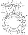
- FIG. 2A there is shown a cross-sectional view of a portion of an acoustic enclosure, a surround type suspension, and a passive radiator diaphragm 10 for illustrating terms used in the specification.
- the passive radiator diaphragm is shown as a planar element, but can take many forms, such as a cone shaped structure, or a structure with one or more non-planar surfaces.
- a suspension system that includes a surround 12 mechanically couples a passive radiator diaphragm 10 to an acoustic enclosure element 14 or some other structure.
- the diaphragm is typically mounted in an opening in acoustic enclosure element 14.
- the surround is designed so that the passive radiator diaphragm can vibrate in a direction indicated by arrow 16, and so that motion in directions transverse to direction 16, such as indicated by arrow 18 is inhibited.
- the suspension supports the weight of the passive radiator diaphragm 10 and seals the passive radiator diaphragm and the enclosure element so that air cannot leak from one side of the enclosure element and diaphragm to the other through the opening in the enclosure element 14.
- the surround may have an outer attachment area 20, and the enclosure element may have a frame structure (not shown).
- the surround may have a passive radiator attachment area 22 to facilitate attaching the surround to the passive radiator diaphragm 10.
- the surround has a roll area 24 that is formed into a geometry that facilitates motion in direction 16. A so called "double roll" configuration is shown, but several other configurations, such as single roll, corrugations, opposed rolls, and the like may be used.
- FIG. 2B is a top plan view of the assembly of FIG. 2A , with the edge 26 of the enclosure element 14 and the edge 28 of the passive radiator diaphragm 10 indicated in dashed lines. Additionally, reference lines indicate correspondence between various points of the surround 12 in the two views.
- the surround is attached to the acoustic enclosure element 14 along outer attachment area 20 and to the passive radiator diaphragm 10 along passive radiator attachment area 22. Attachment is typically by an adhesive or some other fastening element or method. Ideally, the acoustic enclosure element and the passive radiator diaphragm are attached along attachment areas 20 and 22 in an air tight manner, so that air cannot leak from one side of the surround to the other.
- the "width" of the surround is the length w of unattached surround between the enclosure element 14 and the passive radiator diaphragm.
- the suspension assembly includes a surround 12, similar to the surrounds of previous views.
- the suspension assembly includes two or more discrete non-surround suspension elements 32, for example flexures.
- the discrete suspension elements may be attached to the diaphragm at any convenient point (which may be in the attachment area 22, as shown).
- the suspension assembly performs the same functions (controlling direction of motion, supporting the weight of the diaphragm, and pneumatically sealing the acoustic enclosure element and the passive radiator diaphragm) as the suspensions of previous views.
- the surround provides the pneumatic sealing, while the weight supporting and the motion control are provided by the combination of the surround and the non-surround suspension elements.
- passive radiator diaphragm 10 is a planar aluminum disk with a diameter of about 12.5 inches (31.75 cm) and a thickness of about 0.5 inches (1.27 cm).
- the surround is a single roll surround of polyurethane foam 0.05 inches (1.27 mm) thick and 0.8 inches (2.03 cm) wide.
- the non-surround suspension elements include four bands of spring steel 0.006 inches (0.15 mm) thick 1.2 inches (3.05 cm) wide and 1.2 inches (3.05 cm) long.
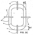
- FIG. 3C shows an alternate configuration of the device of FIGS. 3A and 3B .
- the diaphragm 10 has a so-called "racetrack" shape.
- the diaphragm may have other shapes, such as round or oval, and may take other forms, such as a cone shaped structure.
- FIG. 3C illustrates another feature of the invention that reduces or controls rocking mode vibration.
- the surround is wider (and may also be thicker) at locations that are prone to rocking mode vibration. For example, width w1may be greater than width w2.
- FIGS. 3D and 3E show alternate arrangements of the surround 12 and the discrete non-surround suspension elements 32.
- the discrete non-surround suspension elements 32 and the surround may be mounted to the diaphragm 10 on the same side, as in FIG. 3A or on opposite sides, as shown in FIGS. 3D and 3E .
- a passive radiator suspension according to FIGS. 3A - 3E is advantageous over conventional passive radiator suspensions because the non-surround suspension elements permits sharing of the weight support function between the surround and the non-surround suspension elements. This provides great design flexibility and allows the use of heavy diaphragms without requiring spiders or complex bulky surrounds that may limit the motion of the diaphragm or take up more space than desired, or both.
- the non-surround suspension elements can be placed at positions that are more likely than other positions to be prone to be subject to conditions that cause rocking mode vibration, for example at positions on the diaphragm that are subject to greater stress because of geometry, or where there are pressure differences across the diaphragm.
- the suspension system can be more easily designed so that a loudspeaker incorporating the invention can be oriented so that the intended direction of motion of the passive radiator is either horizontal (so that gravity is a force that is lateral to the direction of motion of the diaphragm) or vertical (so that gravity is a force that is parallel to the direction of motion of the diaphragm).
- the passive radiator suspension may be made more resistant to drift or creep, so that it maintains its characteristics over time. Still further, the suspension may be made less susceptible to deformation of the surround due to pneumatic pressure.
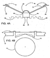
- FIG. 4A - 4C there is shown cross-sectional and plan views of some alternative passive radiator diaphragm designs that control rocking mode vibration illustrating features that can be combined with the inventive features as defined by the accompanying claim 1.
- One method of controlling rocking mode vibration is to control mass distribution of the diaphragm.
- moving mass away from the axis of rotation for any rotational motion of the diaphragm increases the moment of inertia and causes rocking mode vibration to occur at lower frequencies. Moving mass toward the axis of rotation decreases the moment of inertia and causes rocking mode vibration to occur at higher frequencies.
- the diaphragm has the form of a frustoconical surface attached to a surround at the outer edge 54 of the diaphragm and an additional mass 48 attached to the inner edge 56 of the diaphragm, so that the mass is displaced from the rocking axis 46.
- 4A is to use a conventional acoustic driver cone and dust cover 58 for the diaphragm, attaching a tube 60, for example a coil former, or similar element, in a conventional way. Additionally, material may be placed inside the tube so that the additional mass includes the tube and the material that may have been deposited inside the tube. Other rocking mode limiting devices, such as a spider 50, may provide additional rocking mode control.
- the passive radiator diaphragm is thicker at the perimeter than at the center.
- the thickness may increase linearly (as shown by the solid line), may increase exponentially (as shown by the dashed line), or may increase in some regular or irregular manner determined experimentally or by computer simulation.
- FIG. 4C shows another passive radiator diaphragm in which the distribution of mass has been configured to increase (over a uniform thickness diaphragm) the moment of inertia to change a rocking mode frequency.
- the diaphragm of FIG. 4C has a cup shaped form, with a band or ring of material at the perimeter, increasing the mass at the perimeter.
- the diaphragm may be attached to the surround at a point other than the lateral outer extremity of the diaphragm, so that the diaphragm is larger than the opening in which it is mounted.
- the diaphragm has a lateral extension 33 so that the passive radiator diaphragm edge 28 lies outside the edge 26 of the enclosure element 14.
- the lateral extension 33 is offset from the enclosure opening so that the diaphragm does not strike the enclosure during operation.
- the passive radiator attachment area 22 lies inside the perimeter of the diaphragm. If the configuration permits, the passive radiator may be configured so that the ring or band of material and the lateral extension is outside the acoustic enclosure.
- the diaphragm 10 includes a skin element 34 and a mass element 36.
- the skin element 34 may be a unitary structure with the surround 12 as shown, or may be separate from the surround. If the diaphragm is not sufficiently stiff and exhibits membrane behavior, the mass element may include stiffening elements, such as ribs 52, for example.
- the mass element 36 may, for example, be a ring shaped structure as shown in FIG. 6 , providing great concentration of mass at the perimeter and a significantly higher moment of inertia than conventional passive radiator diaphragms.
- the mass element 36 may also take the form of the diaphragms of FIGS. 4A - 4C , with the additional flexibility that the surface of the mass element 36 need not be unbroken or continuous.
- a first inner section 38 may be of a low density material
- an outer section 40 may be of higher density material.
- low density materials may include light papers or plastics, foams, or honeycomb structures that are unfilled or filled with low density material
- examples of higher density materials may include heavy papers or plastics, metal, wood, composites, or honeycomb structures filled with higher density material.
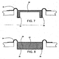
- FIGS. 7 and 8 show variations of the implementation of FIGS. 5 and 6 illustrating features that can be combined with the inventive features as defined by the accompanying claim 1.
- the skin element 34 may encase a sufficient portion (for example more than half of the surface area) so that passive radiator can be assembled without adhesive and so that the elements of the passive radiator remain in position, without adhesive, during operation.
- the skin element 34 may be completely enclose the mass element 36.
- the mass element is formed to increase the moment of inertia as described above.
- diaphragm has the form of FIG. 6 . Since the diaphragm may be sealed, materials such as powders, granular material, liquids, materials that should not be exposed to the environment, and the like can be used for portions of the mass element.
- a passive radiator according to FIGS. 7 and 8 can be formed by insert molding.
- the mass element may be placed in a cavity in a mold.
- the cavity can then be filled with a flowable, curable material so that it partially or completely encloses the mass element.
- the flowable, curable material may then be set or cured so that it is suitable form for, and so that is suitably elastomeric for, use as a passive radiator suspension.
- Suitable materials include thermosettable, thermoplastic, or curable materials such as closed-cell polyurethane foams. Insert molding permits more precise positioning of the mass element 36 relative to the skin element 34 than other manufacturing methods.
- the passive radiator can be made less prone to rocking mode vibration resulting from misalignment of the passive radiator elements. Additionally, the passive radiator can be formed without the use of adhesives, which eliminates a source of mechanical failure and which eliminates manufacturing steps related to the depositing and curing of adhesives.
- a diaphragm assembly may include an unskinned honeycomb portion and a metal portion according to FIG. 6 and a skin element according to FIG. 5 ; the diaphragm may be thicker at the perimeter according to FIGS. 4B or 4C , or both, and have discrete non-surround suspension elements channels according to FIG. 3A .
- Many other combinations are possible.
- FIG. 4B can be manufactured by metal forming or casting, or may be manufactured by removing material from a slug or metal, plastic, or some other material.
- FIG. 4C could be manufactured by metal forming or casting, or by removing material from or adding material to a slug of metal, plastic, or some other material.
Description
- The invention relates to acoustic passive radiators, and more particularly to reducing rocking mode vibration.
- Concerning prior art, the document D2=
US3780824 can be cited, which discloses an acoustic passive radiator, comprising a diaphragm for radiating acoustic energy; a surround for pneumatically sealing said diaphragm and an acoustic enclosure; and a plurality of suspension elements for physically coupling said diaphragm and said acoustic enclosure, wherein said the suspension elements and said surround coact to control the motion of said diaphragm and to support the weight of said diaphragm. - It is an important object of the invention to provide an acoustic passive radiator with reduced rocking mode vibration.
- According to the invention, an acoustic passive radiator includes a diaphragm for radiating acoustic energy; a surround for pneumatically sealing the diaphragm to an acoustic enclosure; and a plurality of discrete, non-surround, non-spider suspension elements for physically coupling the diaphragm and the acoustic enclosure. The non-surround suspension elements and the surround coact to control the motion of the diaphragm and to support the weight of the diaphragm.
- Further aspects of the invention are set out in the accompanying dependent claims.
- Other features, objects, and advantages will become apparent from the following detailed description, when read in connection with the accompanying drawing in which:
-
-
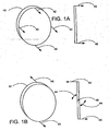
FIGS. 1A and 1B are diagrammatic isometric views of a passive radiator diaphragm for illustrating some terms used in the specification ; -
FIGS. 2A and 2B are views of an acoustic enclosure, a surround type suspension, and a passive radiator diaphragm for illustrating terms used in the specification; -
FIGS. 3A - 3E are views of an enclosure element, a passive radiator diaphragm, and a passive radiator suspension assembly according to one aspect of the invention; -
FIGS. 4A - 4C are views of alternative implementations of passive radiator diaphragms, illustrating features that can be combined with the inventive features as defined by the accompanying claim 1. -
FIG. 5 is a view of an alternative implementation of a passive radiator, illustrating features that can be combined with the inventive features as defined by the accompanying claim 1. -
FIG. 6 is a view of another alternative implementation of a passive radiator illustrating features that can be combined with the inventive features as defined by the accompanying claim 1. -
FIG. 7 is a view of a further implemation of a passive radiator diaphragm and surround assembly illustrating features that can be combined with the inventive features as defined by the accompanying claim 1; and -
FIG. 8 is a view of an alternate implementation of the passive radiator diaphragm and surround assembly ofFIG.7 illustrating features that can be combined with the inventive features as defined by the accompanying claim 1. - With reference now to the drawings and more particularly to
FIGS. 1A and 1B , there are shown views of a passive acoustic radiator diaphragm for illustrating some terms used in the specification. A passive acoustic radiator (sometimes referred to as a "drone") typically includes adiaphragm 10 that is mounted in an acoustic enclosure (not shown) by a suspension system (not shown). An acoustic driver radiates acoustic energy into the acoustic enclosure, causing pressure variations in the enclosure. Thepassive radiator diaphragm 10 vibrates, responsive to the pressure variations in the enclosure. In one common form of passive radiator, the diaphragm and the suspension are designed so that the diaphragm moves pistonically. In pistonic motion, all points on the diaphragm move uniformly along an intended axis of motion, as indicated byvelocity vectors 42, and the points of the diaphragm do not move relative to each other. However, in some circumstances (such as the presence of lateral forces, uneven pressure or acoustic loading across the radiating surface, or suspension nonlinearities) points on the radiating surface may move nonuniformly along the intended axis of motion, so that points of the diaphragm move relative to each other and indicated byvelocity vectors 43 which results in vibratory rotational motion as indicated byarrows 44 about anaxis 46. Non-pistonic motion of the type shown inFIG. 1B is sometimes referred to as "rocking mode" vibration and theaxis 46 is referred to as the rocking axis. Rocking mode vibration has undesirable acoustic effects, such as loss of acoustic efficiency or distortion of the sound radiated by the passive radiator. Rocking mode vibration tends to occur at specific frequencies that are related to characteristics of the diaphragm, the suspension, and the acoustic enclosure, the placement and the mechanical and acoustic characteristics of the acoustic driver, and other factors. Some practices or devices that can alleviate rocking mode vibration, for example multiple surrounds, "spiders," and other suspension elements, and symmetric placement of acoustic drivers relative to passive radiators, are difficult to implement in some types of loudspeaker units, such as compact low frequency woofer or subwoofer loudspeaker units. - The type of rocking mode vibration described above is the most commonly observed form of rocking mode. The devices and techniques disclosed herein generally act to prevent or control other, more complex, forms of rocking mode. For simplicity of explanation, the devices and techniques will be described relative to the type of rocking, mode described above.
- The discussion above also relates to motion of a rigid diaphragm. Other modes, many of which have undesirable acoustic effects, may occur if the diaphragm is not rigid. "Buckling modes" and "potato chip" modes are examples of modes of non-rigid diaphragms that have undesirable acoustic effects. The devices and techniques disclosed herein may act to prevent or control undesirable non-rigid modes. For simplicity of explanation, the devices and techniques will be described as they relate to rocking mode vibration of a rigid diaphragm.
- Referring now to
FIG. 2A , there is shown a cross-sectional view of a portion of an acoustic enclosure, a surround type suspension, and apassive radiator diaphragm 10 for illustrating terms used in the specification. For convenience, the passive radiator diaphragm is shown as a planar element, but can take many forms, such as a cone shaped structure, or a structure with one or more non-planar surfaces. A suspension system that includes a surround 12 mechanically couples apassive radiator diaphragm 10 to anacoustic enclosure element 14 or some other structure. The diaphragm is typically mounted in an opening inacoustic enclosure element 14. The surround is designed so that the passive radiator diaphragm can vibrate in a direction indicated byarrow 16, and so that motion in directions transverse todirection 16, such as indicated byarrow 18 is inhibited. In addition to controlling the motion of thepassive radiator diaphragm 10, the suspension supports the weight of thepassive radiator diaphragm 10 and seals the passive radiator diaphragm and the enclosure element so that air cannot leak from one side of the enclosure element and diaphragm to the other through the opening in theenclosure element 14. To facilitate attaching the surround to theacoustic enclosure element 14, the surround may have anouter attachment area 20, and the enclosure element may have a frame structure (not shown). The surround may have a passiveradiator attachment area 22 to facilitate attaching the surround to thepassive radiator diaphragm 10. The surround has aroll area 24 that is formed into a geometry that facilitates motion indirection 16. A so called "double roll" configuration is shown, but several other configurations, such as single roll, corrugations, opposed rolls, and the like may be used. -
FIG. 2B is a top plan view of the assembly ofFIG. 2A , with theedge 26 of theenclosure element 14 and theedge 28 of thepassive radiator diaphragm 10 indicated in dashed lines. Additionally, reference lines indicate correspondence between various points of thesurround 12 in the two views. The surround is attached to theacoustic enclosure element 14 alongouter attachment area 20 and to thepassive radiator diaphragm 10 along passiveradiator attachment area 22. Attachment is typically by an adhesive or some other fastening element or method. Ideally, the acoustic enclosure element and the passive radiator diaphragm are attached alongattachment areas enclosure element 14 and the passive radiator diaphragm. - Referring to
FIGS. 3A and 3B , there are shown a top plan view and a cross sectional view of an enclosure element 14 apassive radiator diaphragm 10, and a passive radiator suspension assembly according to one aspect of the invention. The suspension assembly includes asurround 12, similar to the surrounds of previous views. In addition to thesurround 12, the suspension assembly includes two or more discretenon-surround suspension elements 32, for example flexures. The discrete suspension elements may be attached to the diaphragm at any convenient point (which may be in theattachment area 22, as shown). The suspension assembly performs the same functions (controlling direction of motion, supporting the weight of the diaphragm, and pneumatically sealing the acoustic enclosure element and the passive radiator diaphragm) as the suspensions of previous views. The surround provides the pneumatic sealing, while the weight supporting and the motion control are provided by the combination of the surround and the non-surround suspension elements. - Use of materials that have good stiffness, good internal damping, and that are thermally stable help to reduce or control rocking modes. In addition to good stiffness, good internal damping, and thermal stability, materials should have other qualities that are desirable for surround material, such as linearity and ease of bonding. For use in small enclosures, thermal stability is especially important. Solid polyurethanes, which have an elastic modulus in the range of 1.4x10⁷ newtons/sq. meter, a tan delta of 0.1, good thermal stability, good linearity, and good bondability, are suitable.
- In one embodiment of the configuration of
FIGS. 3A and 3B ,passive radiator diaphragm 10 is a planar aluminum disk with a diameter of about 12.5 inches (31.75 cm) and a thickness of about 0.5 inches (1.27 cm). The surround is a single roll surround of polyurethane foam 0.05 inches (1.27 mm) thick and 0.8 inches (2.03 cm) wide. The non-surround suspension elements include four bands of spring steel 0.006 inches (0.15 mm) thick 1.2 inches (3.05 cm) wide and 1.2 inches (3.05 cm) long. -
FIG. 3C shows an alternate configuration of the device ofFIGS. 3A and 3B . In the configuration ofFIG. 3C , thediaphragm 10 has a so-called "racetrack" shape. In other configurations, the diaphragm may have other shapes, such as round or oval, and may take other forms, such as a cone shaped structure.FIG. 3C illustrates another feature of the invention that reduces or controls rocking mode vibration. The surround is wider (and may also be thicker) at locations that are prone to rocking mode vibration. For example, width w1may be greater than width w2. -
FIGS. 3D and 3E show alternate arrangements of thesurround 12 and the discretenon-surround suspension elements 32. The discretenon-surround suspension elements 32 and the surround may be mounted to thediaphragm 10 on the same side, as inFIG. 3A or on opposite sides, as shown inFIGS. 3D and 3E . - A passive radiator suspension according to
FIGS. 3A - 3E is advantageous over conventional passive radiator suspensions because the non-surround suspension elements permits sharing of the weight support function between the surround and the non-surround suspension elements. This provides great design flexibility and allows the use of heavy diaphragms without requiring spiders or complex bulky surrounds that may limit the motion of the diaphragm or take up more space than desired, or both. The non-surround suspension elements can be placed at positions that are more likely than other positions to be prone to be subject to conditions that cause rocking mode vibration, for example at positions on the diaphragm that are subject to greater stress because of geometry, or where there are pressure differences across the diaphragm. The suspension system can be more easily designed so that a loudspeaker incorporating the invention can be oriented so that the intended direction of motion of the passive radiator is either horizontal (so that gravity is a force that is lateral to the direction of motion of the diaphragm) or vertical (so that gravity is a force that is parallel to the direction of motion of the diaphragm). Additionally, the passive radiator suspension may be made more resistant to drift or creep, so that it maintains its characteristics over time. Still further, the suspension may be made less susceptible to deformation of the surround due to pneumatic pressure. - Referring to
FIG. 4A - 4C , there is shown cross-sectional and plan views of some alternative passive radiator diaphragm designs that control rocking mode vibration illustrating features that can be combined with the inventive features as defined by the accompanying claim 1. One method of controlling rocking mode vibration is to control mass distribution of the diaphragm. Generally, moving mass away from the axis of rotation for any rotational motion of the diaphragm increases the moment of inertia and causes rocking mode vibration to occur at lower frequencies. Moving mass toward the axis of rotation decreases the moment of inertia and causes rocking mode vibration to occur at higher frequencies. By distributing mass properly, it is possible to cause the rocking mode vibration frequencies to be below or above the operating frequency of the passive radiator. The lower rocking mode frequencies are typically of greater interest, because passive radiators are typically used to augment bass acoustic radiation, and the audio signals sent to loudspeakers employing passive radiators are often low-pass filtered to remove high frequency spectral components. InFIG. 4A , the diaphragm has the form of a frustoconical surface attached to a surround at theouter edge 54 of the diaphragm and anadditional mass 48 attached to theinner edge 56 of the diaphragm, so that the mass is displaced from the rockingaxis 46. One method for forming an implementation ofFIG. 4A is to use a conventional acoustic driver cone anddust cover 58 for the diaphragm, attaching atube 60, for example a coil former, or similar element, in a conventional way. Additionally, material may be placed inside the tube so that the additional mass includes the tube and the material that may have been deposited inside the tube. Other rocking mode limiting devices, such as aspider 50, may provide additional rocking mode control. - In the exemplary implementation of
FIG. 4B illustrating features that can be combined with the inventive features as defined by the accompanying claim 1, the passive radiator diaphragm is thicker at the perimeter than at the center. The thickness may increase linearly (as shown by the solid line), may increase exponentially (as shown by the dashed line), or may increase in some regular or irregular manner determined experimentally or by computer simulation.FIG. 4C shows another passive radiator diaphragm in which the distribution of mass has been configured to increase (over a uniform thickness diaphragm) the moment of inertia to change a rocking mode frequency. The diaphragm ofFIG. 4C has a cup shaped form, with a band or ring of material at the perimeter, increasing the mass at the perimeter. Additionally, the diaphragm may be attached to the surround at a point other than the lateral outer extremity of the diaphragm, so that the diaphragm is larger than the opening in which it is mounted. In one configuration the diaphragm has alateral extension 33 so that the passiveradiator diaphragm edge 28 lies outside theedge 26 of theenclosure element 14. Thelateral extension 33 is offset from the enclosure opening so that the diaphragm does not strike the enclosure during operation. The passiveradiator attachment area 22 lies inside the perimeter of the diaphragm. If the configuration permits, the passive radiator may be configured so that the ring or band of material and the lateral extension is outside the acoustic enclosure. - Referring now to
FIG. 5 , there is shown another alternative passive radiator diaphragm illustrating features that can be combined with the inventive features as defined by the accompanying claim 1. In the implementation ofFIG. 5 , thediaphragm 10 includes askin element 34 and amass element 36. Theskin element 34 may be a unitary structure with thesurround 12 as shown, or may be separate from the surround. If the diaphragm is not sufficiently stiff and exhibits membrane behavior, the mass element may include stiffening elements, such asribs 52, for example. - An implementation according to
FIG. 5 provides even greater flexibility of mass distribution. Themass element 36 may, for example, be a ring shaped structure as shown inFIG. 6 , providing great concentration of mass at the perimeter and a significantly higher moment of inertia than conventional passive radiator diaphragms. Themass element 36 may also take the form of the diaphragms ofFIGS. 4A - 4C , with the additional flexibility that the surface of themass element 36 need not be unbroken or continuous. - Referring now to
FIG. 6 , there is shown another implementation illustrating features that can be combined with the inventive features as defined by the accompanying claim 1. In the implementation ofFIG. 6 , different sections of thediaphragm 10 or of themass element 36 are formed of different material. For example, a firstinner section 38 may be of a low density material, while anouter section 40 may be of higher density material. Examples of low density materials may include light papers or plastics, foams, or honeycomb structures that are unfilled or filled with low density material, while examples of higher density materials may include heavy papers or plastics, metal, wood, composites, or honeycomb structures filled with higher density material. -
FIGS. 7 and 8 show variations of the implementation ofFIGS. 5 and 6 illustrating features that can be combined with the inventive features as defined by the accompanying claim 1. As shown inFIG. 7 , theskin element 34 may encase a sufficient portion (for example more than half of the surface area) so that passive radiator can be assembled without adhesive and so that the elements of the passive radiator remain in position, without adhesive, during operation. In other implementations, (as inFIG. 8 ) theskin element 34 may be completely enclose themass element 36. In the variation shown inFIG. 7 , the mass element is formed to increase the moment of inertia as described above. In the variation shown inFIG. 8 , diaphragm has the form ofFIG. 6 . Since the diaphragm may be sealed, materials such as powders, granular material, liquids, materials that should not be exposed to the environment, and the like can be used for portions of the mass element. - A passive radiator according to
FIGS. 7 and 8 can be formed by insert molding. The mass element may be placed in a cavity in a mold. The cavity can then be filled with a flowable, curable material so that it partially or completely encloses the mass element. The flowable, curable material may then be set or cured so that it is suitable form for, and so that is suitably elastomeric for, use as a passive radiator suspension. Suitable materials include thermosettable, thermoplastic, or curable materials such as closed-cell polyurethane foams. Insert molding permits more precise positioning of themass element 36 relative to theskin element 34 than other manufacturing methods. Because the mass element and the skin element can be more precisely aligned, the passive radiator can be made less prone to rocking mode vibration resulting from misalignment of the passive radiator elements. Additionally, the passive radiator can be formed without the use of adhesives, which eliminates a source of mechanical failure and which eliminates manufacturing steps related to the depositing and curing of adhesives. - The implementations of
FIGS. 3A - 8 may be combined. For example, a diaphragm assembly may include an unskinned honeycomb portion and a metal portion according toFIG. 6 and a skin element according toFIG. 5 ; the diaphragm may be thicker at the perimeter according toFIGS. 4B or4C , or both, and have discrete non-surround suspension elements channels according toFIG. 3A . Many other combinations are possible. - The various configurations and geometries may be manufactured in a variety of ways. For example, the implementations of
FIG. 4B can be manufactured by metal forming or casting, or may be manufactured by removing material from a slug or metal, plastic, or some other material. The implementation ofFIG. 4C could be manufactured by metal forming or casting, or by removing material from or adding material to a slug of metal, plastic, or some other material. - It is evident that those skilled in the art may now make numerous uses of and departures from the specific apparatus and techniques disclosed herein without departing from the inventive concepts. Consequently, the invention is to be construed as embracing each and every novel feature and novel combination of features disclosed herein and limited only by the scope of the appended claims.
Claims (8)
- An acoustic passive radiator, comprising:a diaphragm (10) for radiating acoustic energy;a surround (12) for pneumatically sealing said diaphragm (10) to an acoustic enclosure (14); anda plurality of discrete, non-surround, non-spider suspension elements (32) for physically coupling said diaphragm (10) and said acoustic enclosure (14), wherein said non-surround suspension elements (32) and said surround (12) coact to control the motion of said diaphragm (10) and to support the weight of said diaphragm.
- An acoustic passive radiator in accordance with claim 1, wherein each of said discrete suspension elements (32) comprises a metal band, each of said metal bands having one end constructed and arranged to be attached to said diaphragm (10) and another end constructed and arranged to be attached to said enclosure (14).
- An acoustic passive radiator in accordance with claim 1 or claim 2, wherein said plurality of discrete suspension elements (32) and said surround (12) are constructed and arranged to be attached to said diaphragm (10) at a common point.
- An acoustic passive radiator in accordance with claim 1, 2 or 3, wherein said plurality of discrete suspension elements (32) are mechanically attached to said diaphragm (10) at discrete points, and wherein said surround (12) is mechanically attached to said diaphragm (10) along a continuous surface, wherein said continuous surface includes said discrete points.
- An acoustic passive radiator in accordance with any of claims 1 to 4, wherein said diaphragm (10) is constructed of metal.
- An acoustic passive radiator in accordance with any of claims 1 to 5, wherein said acoustic enclosure (14) has a frame structure to facilitate attaching said surround to said acoustic enclosure (14).
- An acoustic passive radiator in accordance with any of claims 1 to 6, wherein said surround (12) has a non-uniform width.
- An acoustic passive radiator in accordance with claim 7 wherein:said diaphragm (10) has a perimeter portion and a central portion, said perimeter portion being thicker than said central portion;a skin element (34) encasing said diaphragm, said skin element comprising said surround (12) for physically coupling said passive radiator to said acoustic enclosure (14); andsaid discrete suspension elements (32) comprise a non-pneumatically sealing, non-surround, non-spider suspension element.
Applications Claiming Priority (2)
| Application Number | Priority Date | Filing Date | Title |
|---|---|---|---|
| US758336 | 2004-01-15 | ||
| US10/758,336 US7568552B2 (en) | 2004-01-15 | 2004-01-15 | Acoustic passive radiator rocking mode reducing |
Publications (3)
| Publication Number | Publication Date |
|---|---|
| EP1555849A2 EP1555849A2 (en) | 2005-07-20 |
| EP1555849A3 EP1555849A3 (en) | 2007-03-07 |
| EP1555849B1 true EP1555849B1 (en) | 2012-06-06 |
Family
ID=34620695
Family Applications (1)
| Application Number | Title | Priority Date | Filing Date |
|---|---|---|---|
| EP05250033A Not-in-force EP1555849B1 (en) | 2004-01-15 | 2005-01-07 | Acoustic passive radiator with rocking-mode reduction |
Country Status (4)
| Country | Link |
|---|---|
| US (1) | US7568552B2 (en) |
| EP (1) | EP1555849B1 (en) |
| JP (1) | JP4726500B2 (en) |
| CN (2) | CN1642356A (en) |
Families Citing this family (30)
| Publication number | Priority date | Publication date | Assignee | Title |
|---|---|---|---|---|
| US7568552B2 (en) | 2004-01-15 | 2009-08-04 | Bose Corporation | Acoustic passive radiator rocking mode reducing |
| US20090208048A1 (en) * | 2006-05-17 | 2009-08-20 | Nxp B.V. | Loudspeaker with reduced rocking tendency |
| WO2009066415A1 (en) * | 2007-11-20 | 2009-05-28 | Panasonic Corporation | Speaker, video device, and mobile information processing device |
| US8615285B2 (en) * | 2008-04-04 | 2013-12-24 | Mayo Foundation For Medical Education And Research | Passive acoustic driver for magnetic resonance elastography |
| US8281663B2 (en) * | 2008-07-14 | 2012-10-09 | Mayo Foundation For Medical Education And Research | Active acoustic driver for magnetic resonance elastography |
| EP2308242A1 (en) * | 2008-07-28 | 2011-04-13 | Nxp B.V. | Membrane for an acoustic transducer |
| US8295536B2 (en) | 2010-03-31 | 2012-10-23 | Bose Corporation | Moving magnet levered loudspeaker |
| US8295537B2 (en) | 2010-03-31 | 2012-10-23 | Bose Corporation | Loudspeaker moment and torque balancing |
| US9149204B2 (en) | 2011-04-22 | 2015-10-06 | Mayo Foundation For Medical Education And Research | Flexible passive acoustic driver for magnetic resonance elastography |
| US8638975B2 (en) * | 2011-08-17 | 2014-01-28 | Bose Corporation | Wiper seal for passive radiator |
| US9055370B2 (en) | 2012-08-31 | 2015-06-09 | Bose Corporation | Vibration-reducing passive radiators |
| CN202949560U (en) * | 2012-11-16 | 2013-05-22 | 瑞声声学科技(常州)有限公司 | Sounder |
| TWI482504B (en) * | 2013-04-10 | 2015-04-21 | Passive Radiation Speaker Improved Structure | |
| US20140355806A1 (en) | 2013-06-03 | 2014-12-04 | Allen T. Graff | Portable Loudspeaker |
| EP3089478B1 (en) * | 2013-12-27 | 2018-12-05 | Sony Corporation | Edge structure of diaphragm |
| US9148727B1 (en) | 2014-03-19 | 2015-09-29 | Bose Corporation | Non-axisymmetric geometry for cloth loudspeaker suspensions |
| CN105101017B (en) * | 2014-05-23 | 2018-03-30 | 张百良 | The outstanding side of loudspeaker and passive radiator with airtight air chamber |
| JP2016103773A (en) * | 2014-11-28 | 2016-06-02 | 京セラ株式会社 | Sound generator and electronic apparatus using the same |
| US9525932B2 (en) * | 2015-01-26 | 2016-12-20 | Bose Corporation | Acoustic device having active drivers mounted to a passive radiator diaphragm |
| CN204425613U (en) * | 2015-02-02 | 2015-06-24 | 瑞声光电科技(常州)有限公司 | Loudspeaker enclosure |
| CN204425618U (en) * | 2015-02-02 | 2015-06-24 | 瑞声光电科技(常州)有限公司 | Loudspeaker enclosure |
| US10524071B2 (en) * | 2015-02-05 | 2019-12-31 | Eagle Acoustics Manufacturing, Llc | Integrated voice coil and cone assembly and method of making same |
| JP6692182B2 (en) * | 2016-02-29 | 2020-05-13 | 日本マタイ株式会社 | Method for producing functional film |
| CN108012215A (en) * | 2016-11-02 | 2018-05-08 | 深圳市三诺数字科技有限公司 | A kind of ameliorative way and passive radiator of passive radiator distortion |
| EP3457219A1 (en) * | 2017-09-14 | 2019-03-20 | The Swatch Group Research and Development Ltd | Acoustic radiation membrane, and chiming watch provided with the acoustic membrane |
| CN108471575B (en) * | 2018-05-14 | 2020-07-03 | 广东小天才科技有限公司 | Liquid discharge method for loudspeaker of mobile terminal and mobile terminal |
| WO2021000735A1 (en) * | 2019-07-03 | 2021-01-07 | Goertek Inc. | Passive radiator and loudspeaker system |
| US11206470B1 (en) | 2020-09-03 | 2021-12-21 | Apple Inc. | Electronic speaker with a planar foot |
| US11310585B2 (en) * | 2020-09-03 | 2022-04-19 | Apple Inc. | Compact speaker |
| KR20220097667A (en) * | 2020-12-30 | 2022-07-08 | 주식회사 이엠텍 | Diaphragm for waterproof microspeaker |
Family Cites Families (56)
| Publication number | Priority date | Publication date | Assignee | Title |
|---|---|---|---|---|
| US1757345A (en) | 1930-05-06 | Radio tube | ||
| US727634A (en) * | 1901-11-15 | 1903-05-12 | Hutchison Acoustic Company | Telephone. |
| US1757451A (en) * | 1926-02-15 | 1930-05-06 | Craneway Diaphragm Company | Means for suppressing secondary vibrations in diaphragms and the like |
| US1742016A (en) * | 1926-10-06 | 1929-12-31 | Brandes Lab Inc | Sound reproducer |
| US1832832A (en) * | 1930-01-09 | 1931-11-17 | Delaware Chemical Engineering | Sound reproducing means |
| US2713396A (en) | 1950-05-24 | 1955-07-19 | Ernest A Tavares | Novel, small, extended low frequency response, loudspeaker enclosure |
| US3424873A (en) * | 1964-07-15 | 1969-01-28 | Lincoln Walsh | Coherent-sound loudspeaker |
| US3713396A (en) * | 1970-10-02 | 1973-01-30 | Mannix Co Ltd | Single turntable apparatus for positioning railroad ties |
| US3780824A (en) | 1972-08-14 | 1973-12-25 | G Prince | Acoustic loading system |
| US4169516A (en) * | 1976-04-26 | 1979-10-02 | Ichiro Honda | Speaker system |
| JPS53119023A (en) | 1977-03-26 | 1978-10-18 | Kenzou Inoue | Moving coil type sound converting vibration plate |
| US4379951A (en) * | 1977-04-20 | 1983-04-12 | Gabr Saad Z M | Electro-acoustic transducer means |
| JPS5414726A (en) * | 1977-07-06 | 1979-02-03 | Hitachi Ltd | Dome type speaker |
| JPS5551513A (en) * | 1978-10-11 | 1980-04-15 | Okabe Kk | Clamping auxiliary tool of concrete flask and its preparation |
| US4207963A (en) | 1978-12-11 | 1980-06-17 | Integrated Sound Systems Inc. | Loudspeaker system |
| JPS5613896A (en) * | 1979-07-13 | 1981-02-10 | Matsushita Electric Ind Co Ltd | Speaker diaphragm |
| JPS5754498A (en) * | 1980-09-19 | 1982-03-31 | Hitachi Ltd | Speaker |
| JPS57208792A (en) * | 1981-06-19 | 1982-12-21 | Hitachi Ltd | Diaphragm speaker packed with foamed resin |
| JPS58138196A (en) | 1982-02-12 | 1983-08-16 | Matsushita Electric Ind Co Ltd | Diaphragm for loudspeaker |
| JPS58151797A (en) * | 1982-03-05 | 1983-09-09 | Mitsubishi Electric Corp | Diaphragm for speaker |
| JPS59104692A (en) * | 1982-12-07 | 1984-06-16 | キヤノン株式会社 | Electronic equipment |
| JPS6045959B2 (en) * | 1984-08-20 | 1985-10-12 | 三機工業株式会社 | How to prepare materials for rotating filter bed |
| JPS61103393A (en) * | 1984-10-26 | 1986-05-21 | Sony Corp | Edgeless type speaker |
| JPS62161491A (en) * | 1986-01-09 | 1987-07-17 | Mitsubishi Electric Corp | Laser trimming device for optical device |
| JPS63133793A (en) * | 1986-11-25 | 1988-06-06 | Nec Corp | Private branch exchange system |
| US4817165A (en) * | 1987-01-27 | 1989-03-28 | Amalaha Leonard D | Acoustic speaker device with a diaphragm having a spider web type core |
| JPH01272300A (en) * | 1988-04-22 | 1989-10-31 | Matsushita Electric Ind Co Ltd | Speaker system |
| DE3831376A1 (en) | 1988-09-15 | 1990-03-22 | Filip Keller | Loudspeaker or microphone |
| EP0529143A3 (en) | 1991-08-30 | 1993-07-07 | Filip Keller | Diaphragm for loudspeaker or microphone |
| US5319718A (en) | 1991-10-11 | 1994-06-07 | Yocum Fred D | Loudspeaker cone and method for making same |
| EP0548836B1 (en) * | 1991-12-20 | 1997-06-11 | Matsushita Electric Industrial Co., Ltd. | A bass reproduction speaker apparatus |
| DE4213991A1 (en) * | 1992-04-30 | 1993-11-04 | Ingo Kintzel Prototypenbau | Loudspeaker membrane - comprises sandwich structure with carbon fibre facings and rubber core for better elasticity in impulse plane |
| US5418337A (en) * | 1993-05-28 | 1995-05-23 | Bose Corporation | Loudspeaker driver surrounding |
| US5650105A (en) | 1994-05-24 | 1997-07-22 | Yocum; Fred D. | Method for making a loudspeaker cone with an integral surround |
| JP2692040B2 (en) * | 1995-08-29 | 1997-12-17 | フオスター電機株式会社 | Small electroacoustic transducer |
| JP3136959B2 (en) * | 1995-08-31 | 2001-02-19 | 松下電器産業株式会社 | Speaker |
| KR100445211B1 (en) * | 1996-05-31 | 2004-12-08 | 코닌클리케 필립스 일렉트로닉스 엔.브이. | Systems that make passive radiators and passive radiators |
| GB2315185A (en) | 1996-07-09 | 1998-01-21 | B & W Loudspeakers | Diaphragm surrounds for loudspeaker drive units |
| US5734132A (en) | 1996-07-19 | 1998-03-31 | Proni; Lucio | Concentric tube suspension system for loudspeakers |
| AU4230397A (en) * | 1996-08-12 | 1998-03-06 | Robert W. Carver | High back emf, high pressure subwoofer |
| WO1999004597A2 (en) | 1997-07-18 | 1999-01-28 | Mackie Designs Inc. | Pistonic motion, large excursion passive radiator |
| EP0963136B1 (en) * | 1998-05-08 | 2011-08-31 | Panasonic Corporation | Speaker |
| US6385327B1 (en) | 1998-06-16 | 2002-05-07 | U.S. Philips Corporation | Device having two coaxially disposed bodies which are movable relative to one another along a translation axis |
| GB2344248B (en) | 1998-11-24 | 2003-06-04 | B & W Loudspeakers | Auxiliary bass radiator units |
| US6044925A (en) | 1998-11-30 | 2000-04-04 | Sahyoun; Joseph Yaacoub | Passive speaker |
| US6675931B2 (en) | 1998-11-30 | 2004-01-13 | Joseph Yaacoub Sahyoun | Low profile audio speaker |
| US7151836B1 (en) * | 1999-03-31 | 2006-12-19 | Matsushita Electric Industrial Co., Ltd. | Speaker apparatus and sound reproduction apparatus |
| DE20005543U1 (en) * | 2000-03-24 | 2000-06-21 | Peng Jack | Vibration membrane speakers |
| TW511388B (en) | 2000-03-28 | 2002-11-21 | Koninkl Philips Electronics Nv | Passive radiator having mass elements |
| US6607051B1 (en) * | 2000-10-06 | 2003-08-19 | Meiloon Industrial Co., Ltd. | Yoke structure of a speaker diaphragm |
| US6862361B2 (en) * | 2001-04-05 | 2005-03-01 | Floyd John James | Audio speaker |
| US6577742B1 (en) | 2001-05-24 | 2003-06-10 | Paul F. Bruney | Membrane support system |
| GB2403091B (en) * | 2003-06-18 | 2006-08-09 | B & W Loudspeakers | Diaphragms for loudspeaker drive units |
| JP3651472B2 (en) * | 2003-10-14 | 2005-05-25 | 松下電器産業株式会社 | Speaker |
| US7568552B2 (en) | 2004-01-15 | 2009-08-04 | Bose Corporation | Acoustic passive radiator rocking mode reducing |
| US20050194203A1 (en) * | 2004-03-05 | 2005-09-08 | Keiko Muto | Planar speaker edge |
-
2004
- 2004-01-15 US US10/758,336 patent/US7568552B2/en not_active Expired - Fee Related
-
2005
- 2005-01-07 EP EP05250033A patent/EP1555849B1/en not_active Not-in-force
- 2005-01-17 CN CN200510004432.0A patent/CN1642356A/en active Pending
- 2005-01-17 JP JP2005009647A patent/JP4726500B2/en not_active Expired - Fee Related
- 2005-01-17 CN CN2010105398712A patent/CN101969594B/en not_active Expired - Fee Related
Also Published As
| Publication number | Publication date |
|---|---|
| US7568552B2 (en) | 2009-08-04 |
| CN101969594B (en) | 2012-07-04 |
| JP4726500B2 (en) | 2011-07-20 |
| CN1642356A (en) | 2005-07-20 |
| US20050157900A1 (en) | 2005-07-21 |
| EP1555849A2 (en) | 2005-07-20 |
| JP2005204320A (en) | 2005-07-28 |
| EP1555849A3 (en) | 2007-03-07 |
| CN101969594A (en) | 2011-02-09 |
Similar Documents
| Publication | Publication Date | Title |
|---|---|---|
| EP1555849B1 (en) | Acoustic passive radiator with rocking-mode reduction | |
| AU725754B2 (en) | Loudspeakers | |
| EP2564602B1 (en) | Loudspeaker and diaphragm therefor | |
| JP5085318B2 (en) | Acoustic device and acoustic device manufacturing method | |
| EP1762119B1 (en) | Piezoelectric inertial transducer | |
| EP3251377B1 (en) | Acoustic device having active drivers mounted to a passive radiator diaphragm | |
| EP2512155B1 (en) | Low profile loudspeaker transducer | |
| EP0920785B1 (en) | Loudspeaker drive units | |
| EP1892996A1 (en) | Speaker | |
| EP2512153B1 (en) | Loudspeaker magnet assembly | |
| EP2512154B1 (en) | Loudspeaker magnet having a channel | |
| NZ316565A (en) | Inertial vibration sound transducers | |
| JP2009198902A (en) | Sound absorbing structure, sound absorbing structure group, acoustic chamber, method of adjusting sound absorbing structure and noise reduction method | |
| EP2512156B1 (en) | Low profile loudspeaker | |
| US20090208048A1 (en) | Loudspeaker with reduced rocking tendency | |
| US5608810A (en) | Loudspeaker structure | |
| JP5493583B2 (en) | Speaker edge | |
| US20030068064A1 (en) | Neoprene surround for an electro-dynamic acoustical transducer | |
| CN1822714B (en) | Electroacustic convertor | |
| WO2008038021A1 (en) | Shaped loudspeaker | |
| US8240426B2 (en) | Three dimensional acoustic passive radiating | |
| CN217183467U (en) | Passive radiator and speaker system | |
| US20180152782A1 (en) | Air motion transformer passive radiator for loudspeaker | |
| JP2010114866A (en) | Panel-type speaker | |
| US11678122B2 (en) | Speaker |
Legal Events
| Date | Code | Title | Description |
|---|---|---|---|
| PUAI | Public reference made under article 153(3) epc to a published international application that has entered the european phase |
Free format text: ORIGINAL CODE: 0009012 |
|
| AK | Designated contracting states |
Kind code of ref document: A2 Designated state(s): AT BE BG CH CY CZ DE DK EE ES FI FR GB GR HU IE IS IT LI LT LU MC NL PL PT RO SE SI SK TR |
|
| AX | Request for extension of the european patent |
Extension state: AL BA HR LV MK YU |
|
| PUAL | Search report despatched |
Free format text: ORIGINAL CODE: 0009013 |
|
| AK | Designated contracting states |
Kind code of ref document: A3 Designated state(s): AT BE BG CH CY CZ DE DK EE ES FI FR GB GR HU IE IS IT LI LT LU MC NL PL PT RO SE SI SK TR |
|
| AX | Request for extension of the european patent |
Extension state: AL BA HR LV MK YU |
|
| 17P | Request for examination filed |
Effective date: 20070904 |
|
| AKX | Designation fees paid |
Designated state(s): AT BE BG CH CY CZ DE DK EE ES FI FR GB GR HU IE IS IT LI LT LU MC NL PL PT RO SE SI SK TR |
|
| 17Q | First examination report despatched |
Effective date: 20100212 |
|
| GRAP | Despatch of communication of intention to grant a patent |
Free format text: ORIGINAL CODE: EPIDOSNIGR1 |
|
| GRAS | Grant fee paid |
Free format text: ORIGINAL CODE: EPIDOSNIGR3 |
|
| GRAA | (expected) grant |
Free format text: ORIGINAL CODE: 0009210 |
|
| AK | Designated contracting states |
Kind code of ref document: B1 Designated state(s): AT BE BG CH CY CZ DE DK EE ES FI FR GB GR HU IE IS IT LI LT LU MC NL PL PT RO SE SI SK TR |
|
| REG | Reference to a national code |
Ref country code: GB Ref legal event code: FG4D |
|
| REG | Reference to a national code |
Ref country code: CH Ref legal event code: EP Ref country code: AT Ref legal event code: REF Ref document number: 561497 Country of ref document: AT Kind code of ref document: T Effective date: 20120615 |
|
| REG | Reference to a national code |
Ref country code: IE Ref legal event code: FG4D |
|
| REG | Reference to a national code |
Ref country code: DE Ref legal event code: R096 Ref document number: 602005034507 Country of ref document: DE Effective date: 20120802 |
|
| REG | Reference to a national code |
Ref country code: NL Ref legal event code: VDEP Effective date: 20120606 |
|
| PG25 | Lapsed in a contracting state [announced via postgrant information from national office to epo] |
Ref country code: LT Free format text: LAPSE BECAUSE OF FAILURE TO SUBMIT A TRANSLATION OF THE DESCRIPTION OR TO PAY THE FEE WITHIN THE PRESCRIBED TIME-LIMIT Effective date: 20120606 Ref country code: CY Free format text: LAPSE BECAUSE OF FAILURE TO SUBMIT A TRANSLATION OF THE DESCRIPTION OR TO PAY THE FEE WITHIN THE PRESCRIBED TIME-LIMIT Effective date: 20120606 Ref country code: SE Free format text: LAPSE BECAUSE OF FAILURE TO SUBMIT A TRANSLATION OF THE DESCRIPTION OR TO PAY THE FEE WITHIN THE PRESCRIBED TIME-LIMIT Effective date: 20120606 Ref country code: FI Free format text: LAPSE BECAUSE OF FAILURE TO SUBMIT A TRANSLATION OF THE DESCRIPTION OR TO PAY THE FEE WITHIN THE PRESCRIBED TIME-LIMIT Effective date: 20120606 |
|
| REG | Reference to a national code |
Ref country code: AT Ref legal event code: MK05 Ref document number: 561497 Country of ref document: AT Kind code of ref document: T Effective date: 20120606 |
|
| REG | Reference to a national code |
Ref country code: LT Ref legal event code: MG4D Effective date: 20120606 |
|
| PG25 | Lapsed in a contracting state [announced via postgrant information from national office to epo] |
Ref country code: GR Free format text: LAPSE BECAUSE OF FAILURE TO SUBMIT A TRANSLATION OF THE DESCRIPTION OR TO PAY THE FEE WITHIN THE PRESCRIBED TIME-LIMIT Effective date: 20120907 Ref country code: SI Free format text: LAPSE BECAUSE OF FAILURE TO SUBMIT A TRANSLATION OF THE DESCRIPTION OR TO PAY THE FEE WITHIN THE PRESCRIBED TIME-LIMIT Effective date: 20120606 |
|
| PG25 | Lapsed in a contracting state [announced via postgrant information from national office to epo] |
Ref country code: NL Free format text: LAPSE BECAUSE OF FAILURE TO SUBMIT A TRANSLATION OF THE DESCRIPTION OR TO PAY THE FEE WITHIN THE PRESCRIBED TIME-LIMIT Effective date: 20120606 Ref country code: SK Free format text: LAPSE BECAUSE OF FAILURE TO SUBMIT A TRANSLATION OF THE DESCRIPTION OR TO PAY THE FEE WITHIN THE PRESCRIBED TIME-LIMIT Effective date: 20120606 Ref country code: AT Free format text: LAPSE BECAUSE OF FAILURE TO SUBMIT A TRANSLATION OF THE DESCRIPTION OR TO PAY THE FEE WITHIN THE PRESCRIBED TIME-LIMIT Effective date: 20120606 Ref country code: EE Free format text: LAPSE BECAUSE OF FAILURE TO SUBMIT A TRANSLATION OF THE DESCRIPTION OR TO PAY THE FEE WITHIN THE PRESCRIBED TIME-LIMIT Effective date: 20120606 Ref country code: BE Free format text: LAPSE BECAUSE OF FAILURE TO SUBMIT A TRANSLATION OF THE DESCRIPTION OR TO PAY THE FEE WITHIN THE PRESCRIBED TIME-LIMIT Effective date: 20120606 Ref country code: RO Free format text: LAPSE BECAUSE OF FAILURE TO SUBMIT A TRANSLATION OF THE DESCRIPTION OR TO PAY THE FEE WITHIN THE PRESCRIBED TIME-LIMIT Effective date: 20120606 Ref country code: IS Free format text: LAPSE BECAUSE OF FAILURE TO SUBMIT A TRANSLATION OF THE DESCRIPTION OR TO PAY THE FEE WITHIN THE PRESCRIBED TIME-LIMIT Effective date: 20121006 Ref country code: CZ Free format text: LAPSE BECAUSE OF FAILURE TO SUBMIT A TRANSLATION OF THE DESCRIPTION OR TO PAY THE FEE WITHIN THE PRESCRIBED TIME-LIMIT Effective date: 20120606 |
|
| PG25 | Lapsed in a contracting state [announced via postgrant information from national office to epo] |
Ref country code: PT Free format text: LAPSE BECAUSE OF FAILURE TO SUBMIT A TRANSLATION OF THE DESCRIPTION OR TO PAY THE FEE WITHIN THE PRESCRIBED TIME-LIMIT Effective date: 20121008 Ref country code: PL Free format text: LAPSE BECAUSE OF FAILURE TO SUBMIT A TRANSLATION OF THE DESCRIPTION OR TO PAY THE FEE WITHIN THE PRESCRIBED TIME-LIMIT Effective date: 20120606 Ref country code: IT Free format text: LAPSE BECAUSE OF FAILURE TO SUBMIT A TRANSLATION OF THE DESCRIPTION OR TO PAY THE FEE WITHIN THE PRESCRIBED TIME-LIMIT Effective date: 20120606 |
|
| PLBE | No opposition filed within time limit |
Free format text: ORIGINAL CODE: 0009261 |
|
| STAA | Information on the status of an ep patent application or granted ep patent |
Free format text: STATUS: NO OPPOSITION FILED WITHIN TIME LIMIT |
|
| PG25 | Lapsed in a contracting state [announced via postgrant information from national office to epo] |
Ref country code: DK Free format text: LAPSE BECAUSE OF FAILURE TO SUBMIT A TRANSLATION OF THE DESCRIPTION OR TO PAY THE FEE WITHIN THE PRESCRIBED TIME-LIMIT Effective date: 20120606 Ref country code: ES Free format text: LAPSE BECAUSE OF FAILURE TO SUBMIT A TRANSLATION OF THE DESCRIPTION OR TO PAY THE FEE WITHIN THE PRESCRIBED TIME-LIMIT Effective date: 20120917 |
|
| 26N | No opposition filed |
Effective date: 20130307 |
|
| REG | Reference to a national code |
Ref country code: DE Ref legal event code: R097 Ref document number: 602005034507 Country of ref document: DE Effective date: 20130307 |
|
| PG25 | Lapsed in a contracting state [announced via postgrant information from national office to epo] |
Ref country code: BG Free format text: LAPSE BECAUSE OF FAILURE TO SUBMIT A TRANSLATION OF THE DESCRIPTION OR TO PAY THE FEE WITHIN THE PRESCRIBED TIME-LIMIT Effective date: 20120906 |
|
| PG25 | Lapsed in a contracting state [announced via postgrant information from national office to epo] |
Ref country code: MC Free format text: LAPSE BECAUSE OF NON-PAYMENT OF DUE FEES Effective date: 20130131 |
|
| REG | Reference to a national code |
Ref country code: CH Ref legal event code: PL |
|
| GBPC | Gb: european patent ceased through non-payment of renewal fee |
Effective date: 20130107 |
|
| REG | Reference to a national code |
Ref country code: IE Ref legal event code: MM4A |
|
| REG | Reference to a national code |
Ref country code: FR Ref legal event code: ST Effective date: 20130930 |
|
| PG25 | Lapsed in a contracting state [announced via postgrant information from national office to epo] |
Ref country code: CH Free format text: LAPSE BECAUSE OF NON-PAYMENT OF DUE FEES Effective date: 20130131 Ref country code: LI Free format text: LAPSE BECAUSE OF NON-PAYMENT OF DUE FEES Effective date: 20130131 |
|
| PG25 | Lapsed in a contracting state [announced via postgrant information from national office to epo] |
Ref country code: GB Free format text: LAPSE BECAUSE OF NON-PAYMENT OF DUE FEES Effective date: 20130107 Ref country code: FR Free format text: LAPSE BECAUSE OF NON-PAYMENT OF DUE FEES Effective date: 20130131 |
|
| PG25 | Lapsed in a contracting state [announced via postgrant information from national office to epo] |
Ref country code: IE Free format text: LAPSE BECAUSE OF NON-PAYMENT OF DUE FEES Effective date: 20130107 |
|
| PG25 | Lapsed in a contracting state [announced via postgrant information from national office to epo] |
Ref country code: TR Free format text: LAPSE BECAUSE OF FAILURE TO SUBMIT A TRANSLATION OF THE DESCRIPTION OR TO PAY THE FEE WITHIN THE PRESCRIBED TIME-LIMIT Effective date: 20120606 |
|
| PG25 | Lapsed in a contracting state [announced via postgrant information from national office to epo] |
Ref country code: HU Free format text: LAPSE BECAUSE OF FAILURE TO SUBMIT A TRANSLATION OF THE DESCRIPTION OR TO PAY THE FEE WITHIN THE PRESCRIBED TIME-LIMIT; INVALID AB INITIO Effective date: 20050107 Ref country code: LU Free format text: LAPSE BECAUSE OF NON-PAYMENT OF DUE FEES Effective date: 20130107 |
|
| PGFP | Annual fee paid to national office [announced via postgrant information from national office to epo] |
Ref country code: DE Payment date: 20190129 Year of fee payment: 15 |
|
| REG | Reference to a national code |
Ref country code: DE Ref legal event code: R119 Ref document number: 602005034507 Country of ref document: DE |
|
| PG25 | Lapsed in a contracting state [announced via postgrant information from national office to epo] |
Ref country code: DE Free format text: LAPSE BECAUSE OF NON-PAYMENT OF DUE FEES Effective date: 20200801 |