EP1555794A1 - Mobilfunkgerät vom Typ an zwei verschiedenen Modulen - Google Patents
Mobilfunkgerät vom Typ an zwei verschiedenen Modulen Download PDFInfo
- Publication number
- EP1555794A1 EP1555794A1 EP05290037A EP05290037A EP1555794A1 EP 1555794 A1 EP1555794 A1 EP 1555794A1 EP 05290037 A EP05290037 A EP 05290037A EP 05290037 A EP05290037 A EP 05290037A EP 1555794 A1 EP1555794 A1 EP 1555794A1
- Authority
- EP
- European Patent Office
- Prior art keywords
- module
- frequency
- signals
- transmission
- mobile telephone
- Prior art date
- Legal status (The legal status is an assumption and is not a legal conclusion. Google has not performed a legal analysis and makes no representation as to the accuracy of the status listed.)
- Granted
Links
- 230000005540 biological transmission Effects 0.000 claims abstract description 57
- 230000011664 signaling Effects 0.000 claims description 16
- 230000008859 change Effects 0.000 claims description 8
- 230000003287 optical effect Effects 0.000 claims description 3
- 230000005236 sound signal Effects 0.000 description 10
- 238000004891 communication Methods 0.000 description 5
- 230000003993 interaction Effects 0.000 description 4
- 238000000034 method Methods 0.000 description 4
- 230000003321 amplification Effects 0.000 description 3
- 238000003199 nucleic acid amplification method Methods 0.000 description 3
- 238000010521 absorption reaction Methods 0.000 description 2
- 230000008901 benefit Effects 0.000 description 2
- 230000008569 process Effects 0.000 description 2
- 241000861223 Issus Species 0.000 description 1
- 230000002457 bidirectional effect Effects 0.000 description 1
- 230000002089 crippling effect Effects 0.000 description 1
- 238000001514 detection method Methods 0.000 description 1
- 230000000694 effects Effects 0.000 description 1
- 230000005855 radiation Effects 0.000 description 1
- 230000002123 temporal effect Effects 0.000 description 1
- 230000017105 transposition Effects 0.000 description 1
Images
Classifications
-
- H—ELECTRICITY
- H04—ELECTRIC COMMUNICATION TECHNIQUE
- H04B—TRANSMISSION
- H04B1/00—Details of transmission systems, not covered by a single one of groups H04B3/00 - H04B13/00; Details of transmission systems not characterised by the medium used for transmission
- H04B1/38—Transceivers, i.e. devices in which transmitter and receiver form a structural unit and in which at least one part is used for functions of transmitting and receiving
-
- H—ELECTRICITY
- H04—ELECTRIC COMMUNICATION TECHNIQUE
- H04M—TELEPHONIC COMMUNICATION
- H04M1/00—Substation equipment, e.g. for use by subscribers
- H04M1/02—Constructional features of telephone sets
- H04M1/0202—Portable telephone sets, e.g. cordless phones, mobile phones or bar type handsets
- H04M1/0254—Portable telephone sets, e.g. cordless phones, mobile phones or bar type handsets comprising one or a plurality of mechanically detachable modules
- H04M1/0256—Portable telephone sets, e.g. cordless phones, mobile phones or bar type handsets comprising one or a plurality of mechanically detachable modules wherein the modules are operable in the detached state, e.g. one module for the user interface and one module for the transceiver
Definitions
- the present invention relates to a mobile phone of the two-module type distinct.
- a mobile phone can emit radiation electromagnetic properties that may affect nearby tissues, including the head of the user when the phone is placed against his ear while he is in communication.
- An objective reference quantity linked to the power has been defined body tissue and that it is desirable that a mobile phone does not go over. This quantity is called absorption rate specific or more commonly SAR (Specific Absorption Rate). It is the subject of standardized values that manufacturers are required not to exceed.
- the first module includes, on the one hand, all the elements for the processing of the received radio frequency signals, namely a receiving antenna, a radio frequency amplifier, a demodulator of the type GMSK, a decoder of digital signals into audio signals and a loudspeaker and, on the other hand, a microphone.
- the second module includes all the elements for the processing of radio frequency signals to be transmitted, namely a encoder of audio signals into digital signals, a modulator of the GMSK type, a radio frequency amplifier and a transmitting antenna, except the microphone.
- the first and the second modules are connected to each other by a radio frequency link low frequency so that the audio signals generated by the microphone of the first module can be transmitted to the encoder of the second module.
- the first module comprises a low-frequency radio-frequency transmitter the frequency at which the audio signals of the microphone are applied
- the second module has a receiver corresponding to this transmitter which is connected to the input of the encoder to transmit the audio signals received from the transmitter.
- any mobile phone there is a permanent interaction between the chain of reception and the transmission channel. Indeed, the emitted signals must be positioned in time precisely with respect to the signals received. Moreover, in a way Generally speaking, most of the transmitting functions of a mobile phone are controlled by a signaling protocol received from the infrastructure on the reception channel (designation of the channel to be used for transmission, power remote control, etc.).
- the purpose of the present invention is to propose a mobile phone which is consisting of two separate modules, one of which may be distant from the head of the user during a communication, thus taking up the concept described in particular in GB-A-2 364 846 as a solution to the problem of a SAR too much high, but whose architecture is such that the interaction of the transmission and the reception chain is relatively simple to implement.
- a mobile phone is of the type comprising a transmission channel intended to receive the signals of a microphone and to deliver corresponding signals modulated on a carrier at a frequency f 0 , an amplifier for driving a signal. transmitting antenna for transmitting said modulated signals as radiofrequency signals, and a reception channel for receiving and retrieving the received radio frequency signals, said transmission system and said reception channel being controlled by a management unit, said mobile phone comprising two separate modules.
- the transmission means and the receiving means provide a wired link, optical or radio.
- the transposed frequency obtained by the frequency changing means of said first module is zero.
- the transmission means and the means of receive a radio link at a frequency of 2.45 GHz.
- information concerning the transmission power level of said telephone are transmitted via said means transmission and reception means, from said first module to said second module where they are supplied to a control input of said amplifier for controlling its output power level.
- information concerning the frequency of the transmission carrier of said telephone are transmitted via said transmitting means and said receiving means, of said first auditing module second module where they are provided to a control input means of frequency change.
- said first module comprises a multiplexer provided for multiplexing signals carrying said information with the transposed frequency signals and said second module comprises a demultiplexer for delivering the transposed frequency signals, on the one hand, and the signals carrying said information, on the other hand.
- said information modulates a carrier to thereby form said signals carrying said information, said multiplexer and said demultiplexer being of the frequency division type.
- a signaling channel is provided between said first module and said second module on which signaling for establishing the connection between the transmission means of said first module and the receiving means of said second module so as to ensure that they are matched.
- a signaling channel is provided between said first module and said second module on which signaling to verify the integrity of the connection between the transmission means of said first module and the means for receiving said second module.
- the present invention also relates to a mobile telephone system which is characterized in that it comprises a mobile phone as defined above and at least one other module identical to said second module of said mobile phone.
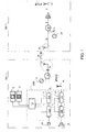
- a mobile telephone apparatus such as that which is shown in FIG. 1 has two separate modules 100 and 200 intended to be distant from each other over relatively short predetermined distances, by example of the order of one meter.
- the first module 100 comprises, on the one hand, all of the transmission means necessary for the transmission of radio frequency signals from the sound signals emitted by the user in front of a microphone 10, with the exception, however, of the amplifier 30 and the transmission antenna 31 which are included in the second module 200.
- the first module 100 further comprises all the means of reception and retrieval for the reception of radiofrequency signals generally issued by a base station of a mobile telephone network and at the return of the corresponding sound signals to a loudspeaker or earphone 18.
- the first module 100 comprises a transmission channel 11 consisting of an encoder 11a and a modulator 11b.
- the microphone 10 is connected to the input of the encoder 11a of the transmission chain 11 to transmit the signals corresponding to the sound signals it receives in order to encode them into signals digital.
- the coding in question here can encompass not only coding sound signals as such but also other operations such as a channel coding, interleaving, encryption and adding information for detection and error correction and for synchronization.
- the result of this coding taken broad sense of the term is a digital signal usually in the form of frames successive information containing all the information to recover the sound signal original.
- the signal digital is a Time Division Multiplexing Access TDMA frame 4.6 ms with eight time slots of 0.57 ms.
- the output of the encoder 11a is connected to the input of the modulator 11b whose function is to modulate a carrier at the frequency f 0 with the digital signals delivered by the encoder 11a.
- the modulation performed by the modulator 12a could be of any digital type (meaning that the modulating signal is digital), such as the types of modulation FSK, PSK, QPSK, MSK, GMSK, etc.
- the modulation operated by the modulator 11b is a modulation of the GMSK (Gaussian Minimum) type Shift Keying).
- the means of reception and restitution consist of a chain of reception 12 itself consists of a demodulator 12a operating on the signals radio frequencies received from an antenna 16 and an inverse type demodulation of the modulation performed by the modulator 11b.
- the demodulated signals are provided at the input of a decoder 12b which performs an inverse decoding of the coding carried out by the encoder 11a.
- the decoded signals are provided, generally after amplification, at a playback means 18 such as a speaker or earphone.
- a management unit 19 controls the encoder 11a and the modulator 11b of the transmission channel 11 and the control of the demodulator 12a and the decoder 12b of the reception channel 12 and their interaction according to the standard set such as the temporal timing of the transmission with respect to reception, management of radio resources according to the protocol received from the infrastructure, etc. She is also connected to a screen E and a keyboard C ensuring a man / machine interface. As will be understood later, the invention requires only a single unit of management 19 which is placed in the first module 100. No management signal is transmitted to the second module 200. This results in the advantage that the transmission channel 11 and the reception chain 12 can be made by a single component 110, such as a processor called DSP (Digital Signal Processor) used in time sharing.
- DSP Digital Signal Processor
- the frequency f 0 of the modulation carrier operated by the modulator 11b is not necessarily the transmission frequency of the mobile phone which will be noted f. Even this frequency f 0 could be zero according to the present invention.
- the radiofrequency signals delivered by the modulator 11b are supplied to frequency changing means 14 whose function is to transpose the initially modulated signals onto a carrier at the frequency f 0 (which can be zero) to a carrier frequency f T.
- the frequency changing means 14 may consist of a mixer with two inputs, one receiving the signals modulated at the frequency fo and the other receiving a sinusoidal signal, by example generated by a suitable oscillator 17 fixed frequency equal to either a frequency f T + f 0 , or a frequency f T - f 0 .
- the resulting signal is a modulated signal corresponding to the modulated input signal but transposed to two carrier frequencies, one being the sum of the frequencies of the input signals, the other being the difference.
- the frequency changing means 14 incorporate a filter to eliminate one of the two resulting frequencies, which is the least practical for the implementation of the invention.
- the signals at the output of the frequency change means 14 are supplied to transmission means 15, constituted in the exemplary embodiment shown, by a appropriate amplifier and an antenna.
- the second module 200 comprises receiving means 26, constituted in this case by an antenna, provided for receive the signals received from the transmitting means 15. Between the transmission means 15 and the reception means 26, is established a transmission link.
- the signals at the output of the reception means 26 are supplied to frequency changing means 29 whose function is to transpose the modulated received signals at the carrier frequency f T into signals modulated at the carrier frequency f.
- the frequency changing means 29 may consist of a mixer with two inputs, one receiving the modulated signals at the carrier frequency f T and the other receiving a sinusoidal signal, by example generated by an appropriate oscillator 25, either at a frequency f + f T equal to the sum of the transmission frequency f and the transposed frequency f T , or at a frequency f - f T f T equal to the difference of the emission frequency f and the transposed frequency f T.
- the means 29 incorporate a filter to eliminate the unwanted frequency.
- the signals at the output of the frequency change means 29 are radiofrequency signals ready to be emitted after amplification.
- it is therefore digital frames TDMA modulating in GMSK a frequency carrier f.
- the second module 200 further comprises an amplifier 30 whose input is connected to the output of the means 29 and whose output attacks a transmitting antenna 31.
- the transmitting means 15 and the receiving means 26 may be of any type provided that they transmit the modulated signals at the transposed frequency f T.
- the link they provide could be wired, optical (eg infra-red), or hertzian.
- the energy radiated by this link is weak compared to that emitted by the antenna 31, so that the invention solves the SAR issues discussed in the preamble of this description.
- the second module 200 that radiates the most energy at high frequency that can be damaging to the tissues of the user's head. Now, this second module 200 the fact that it is possible to move it away from the first module 100 could be brought to a less sensitive user's body location, for example at the waist.
- the transposed frequency f T is advantageously 2.45 GHz, which is a legally available frequency for any type of application.
- the transposed frequency f T could be zero, meaning that the signal at the output of the frequency changing means 14 is identical to the signal modulating at the output of the encoder 11a.
- the advantage of the invention lies in the fact that the modulation process, as well as any transmission process with the exception of amplification, are carried out under the control of the management unit 19 and, therefore, in the first module 100.
- each phone must, under the command of the base station with which it is in communication, to control its power of emission. It is possible to perform this command in the first module 100 at the chain level 11 under the supervision of the management unit 19, but, for questions of performance, it would be better to perform it at the level of the power amplifier 30. In the embodiment of FIG. 1, this is not possible since the power amplifier 30 is out of control of the management unit 19.
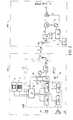
- the first module 100 comprises a multiplexer 13 whose first input receives the coded signal from the modulator 11b and whose second input receives a signal containing the transmission power level information A.
- the second module 200 comprises a demultiplexer 27 provided for outputting on one output the modulated signal at the transposed frequency f T and on the other output the signal containing the transmission power level information, which is supplied to the control input of the amplifier 30.
- the multiplexing operated by the multiplexer 13 could be of any type, for example a time or frequency multiplexing.
- the modulated signals from the modulator 12a are at the frequency f 0 while the power level information signals are modulated at a frequency f 1 in a modulator 32.
- the first are at the frequency f T while the second are at the frequency f 1 - f 0 + f T.
- the demultiplexer 27 will be of the type delivering on a first output the signals at the frequency f T and, on the other output, the signals at the frequency f 1 - fo + f T.
- a demodulator 28 covers the control signal A which is then supplied to the amplifier 30.
- multiplexer 13 could be provided at the output of the means of frequency change 14.
- the frequency of the final transmission carrier f of a mobile phone can be changed, under the command of the base station with which this phone is in communication, frame to frame. Frequency jumps of the carrier are then provided frame to frame.
- the information F concerning the frequency of the transmission carrier which are available at the output of the management unit 19, are transmitted via the transmission means 15 and the means of receiving 26, the first module 100 to the second module 200 where they are provided to a control input of the frequency changing means 29.
- a signal carrying the frequency information of the carrier is multiplexed, for example in the multiplexer 13, with the coded signal from the modulator 11b and, in the second module 200, it is demultiplexed, for example by the demultiplexer 27, the information F being extracted from the signal thus demultiplexed, for example in unit 28 to be then delivered to the control input means 29.
- the signal carrying the information is a signal resulting from the modulation of a carrier at the frequency f 2 by the carrier frequency information.
- the information concerning the transmission carrier frequency may be the number n.
- the frequency changing means 14 perform a transposition of the frequency f 0 to the transposed frequency f T.
- the information n after transmission of the first module 100 to the module 200 via the transmission means 15 and the reception means 26, is available, after demultiplexing by the demultiplexer 27 and demodulation in the demodulator 28, to the input of the frequency changing means 29 which will then effect the change of frequency of the transposed frequency f T to the frequency of the desired carrier: f 0 + ⁇ f x n.
- This can be accomplished by mixing the radio frequency signal at the frequency f T with a sinusoidal signal at the frequency f 0 - f T + ⁇ f xn, for example, delivered by a suitable oscillator whose frequency is controlled by n.
- a channel of signaling is established between the first module 100 and the second module 200.
- channel which can be bidirectional, signaling information S flows for verify the integrity of the connection between the transmitting means 15 and the means of 26.
- These signaling signals S can also be used to establish the connection between the transmitting means 15 and the receiving means 26 so as to ensure that the first module 100 and the second module 200 are paired and that one can not communicate with another of the same type but from another phone according to the present invention.
- these signaling signals are managed by the unit 29 while in the second module 200, they are by a management unit of signaling 35.
- the signaling channel may be set at a frequency offset by a certain amount from the transposed frequency f T , in the first module direction 100 to the second module 200, and by another amount in the other direction.
- the first module 100 establishes and maintains communication with a second module 200.
- a mobile phone according to the present invention can be associated with at least one another module identical to its second module 200 to constitute a system of mobile phone.
Landscapes
- Engineering & Computer Science (AREA)
- Computer Networks & Wireless Communication (AREA)
- Signal Processing (AREA)
- Mobile Radio Communication Systems (AREA)
Applications Claiming Priority (2)
| Application Number | Priority Date | Filing Date | Title |
|---|---|---|---|
| FR0400277 | 2004-01-13 | ||
| FR0400277A FR2865093B1 (fr) | 2004-01-13 | 2004-01-13 | Telephone mobile du type a deux modules distincts |
Publications (2)
| Publication Number | Publication Date |
|---|---|
| EP1555794A1 true EP1555794A1 (de) | 2005-07-20 |
| EP1555794B1 EP1555794B1 (de) | 2008-03-19 |
Family
ID=34610763
Family Applications (1)
| Application Number | Title | Priority Date | Filing Date |
|---|---|---|---|
| EP20050290037 Ceased EP1555794B1 (de) | 2004-01-13 | 2005-01-06 | Mobilfunkgerät vom Typ an zwei verschiedenen Modulen |
Country Status (3)
| Country | Link |
|---|---|
| EP (1) | EP1555794B1 (de) |
| DE (1) | DE602005005368T2 (de) |
| FR (1) | FR2865093B1 (de) |
Citations (5)
| Publication number | Priority date | Publication date | Assignee | Title |
|---|---|---|---|---|
| EP0840465A2 (de) * | 1996-10-31 | 1998-05-06 | Nokia Mobile Phones Ltd. | Benutzerschnittstelle eines Mobiltelefons |
| GB2340691A (en) * | 1998-08-15 | 2000-02-23 | Univ Bristol | Mobile phone arrangement for limiting high frequency radiation exposure |
| WO2000056051A1 (en) * | 1999-03-12 | 2000-09-21 | Mti, Inc. | Cellular telephone with reduced radiation exposure |
| DE10237098A1 (de) * | 2002-05-29 | 2003-12-24 | Lite On Technology Co | Verfahren zum Trennen der Benutzerschnittstelle eines Mobiltelefons |
| WO2004025929A2 (en) * | 2002-09-09 | 2004-03-25 | Vertu Ltd | Cellular radio telephone |
-
2004
- 2004-01-13 FR FR0400277A patent/FR2865093B1/fr not_active Expired - Fee Related
-
2005
- 2005-01-06 DE DE200560005368 patent/DE602005005368T2/de not_active Expired - Lifetime
- 2005-01-06 EP EP20050290037 patent/EP1555794B1/de not_active Ceased
Patent Citations (5)
| Publication number | Priority date | Publication date | Assignee | Title |
|---|---|---|---|---|
| EP0840465A2 (de) * | 1996-10-31 | 1998-05-06 | Nokia Mobile Phones Ltd. | Benutzerschnittstelle eines Mobiltelefons |
| GB2340691A (en) * | 1998-08-15 | 2000-02-23 | Univ Bristol | Mobile phone arrangement for limiting high frequency radiation exposure |
| WO2000056051A1 (en) * | 1999-03-12 | 2000-09-21 | Mti, Inc. | Cellular telephone with reduced radiation exposure |
| DE10237098A1 (de) * | 2002-05-29 | 2003-12-24 | Lite On Technology Co | Verfahren zum Trennen der Benutzerschnittstelle eines Mobiltelefons |
| WO2004025929A2 (en) * | 2002-09-09 | 2004-03-25 | Vertu Ltd | Cellular radio telephone |
Also Published As
| Publication number | Publication date |
|---|---|
| FR2865093A1 (fr) | 2005-07-15 |
| DE602005005368D1 (de) | 2008-04-30 |
| DE602005005368T2 (de) | 2009-04-23 |
| FR2865093B1 (fr) | 2006-03-10 |
| EP1555794B1 (de) | 2008-03-19 |
Similar Documents
| Publication | Publication Date | Title |
|---|---|---|
| Cho et al. | Trans-atlantic field trial using high spectral efficiency probabilistically shaped 64-QAM and single-carrier real-time 250-Gb/s 16-QAM | |
| EP0610988B1 (de) | Mehrbenutze Spreizspektrum-Kommunikationsanordnung | |
| EP0660559B1 (de) | Mehrträger-Frequenzsprungkommunikationssystem | |
| EP1070401A1 (de) | Signal eines zellularen funktelefonsystems mit zusätzlichem abwärtskanal und dafür geeignetes verfahren, system, mobilstation und basisstation | |
| FR2667208A1 (fr) | Procede et systeme pour identifier des creneaux temporels de canal de commande dans un reseau radiotelephonique cellulaire. | |
| EP2400723A1 (de) | Verwaltungsverfahren der Datenübertragungen über eine Schnittstelle vom Typ Bluetooth | |
| EP0095959A1 (de) | Funkverbindungssystem nach dem Frequenzsprungverfahren | |
| EP0631400A1 (de) | Tragbare Sende-Empfängeranordnung für digitale Signale mit 2 Betriebsarten | |
| FR2667747A1 (fr) | Systeme de transmission comportant une pluralite de dispositifs d'abonne. | |
| US7620328B2 (en) | Multi-wavelength optical CDMA with differential encoding and bipolar differential detection | |
| EP0961264B1 (de) | Sende- und Empfangsvorrichtung zur Auswahl eines Quellenkodierers und Verfahren dazu | |
| EP1555794B1 (de) | Mobilfunkgerät vom Typ an zwei verschiedenen Modulen | |
| EP0006807B1 (de) | Anordnung für eine multiplexierte Funkübertragung | |
| FR2812509A1 (fr) | Procede de reconnaissance securisee entre deux appareils d'un reseau radiofrequence | |
| EP1665846B1 (de) | Fernsprechkommunikationssystem für verschiedene verschlüsselte oder unverschlüsselte betriebsarten | |
| WO1999037108A1 (fr) | Equipement de radiocommunication a mode de communication securisee, et unite d'extension faisant partie d'un tel equipement | |
| FR2809905A1 (fr) | Procede de transfert avec traitement de signaux entre deux interfaces d'emission/reception distinctes | |
| FR2721756A1 (fr) | Système d'antennes d'émission-réception omnidirectionnel à diversité angulaire et de polarisation. | |
| EP4566195A1 (de) | Durch eine luft- oder raumvorrichtung implementiertes verfahren zur kommunikation mit mindestens einem endgerät und zugehörige vorrichtung, system und computerprogramm | |
| EP0305261B1 (de) | Verfahren zur schnellen Synchronisation von Vocodern, welche mittels Verschlüsselungs- und Entschlüsselungseinrichtungen verbunden sind | |
| FR2690025A1 (fr) | Procédé et appareil de décalage de fréquence pour émetteur-récepteur. | |
| Perić et al. | An experiment with real-time data transmission over global scale mobile voice channel | |
| JP2001308828A (ja) | 無線機における秘話化方法及び秘話化装置 | |
| EP0322059A1 (de) | Verfahren und Vorrichtung zur Tonverschlüsselung oder -entschlüsselung | |
| EP0725544A1 (de) | Verfahren zum Versetzen eines Verschlüsslers für Fernsehsignale |
Legal Events
| Date | Code | Title | Description |
|---|---|---|---|
| PUAI | Public reference made under article 153(3) epc to a published international application that has entered the european phase |
Free format text: ORIGINAL CODE: 0009012 |
|
| AK | Designated contracting states |
Kind code of ref document: A1 Designated state(s): AT BE BG CH CY CZ DE DK EE ES FI FR GB GR HU IE IS IT LI LT LU MC NL PL PT RO SE SI SK TR |
|
| AX | Request for extension of the european patent |
Extension state: AL BA HR LV MK YU |
|
| 17P | Request for examination filed |
Effective date: 20050806 |
|
| AKX | Designation fees paid |
Designated state(s): DE GB |
|
| RAP1 | Party data changed (applicant data changed or rights of an application transferred) |
Owner name: SAGEM COMMUNICATION |
|
| 17Q | First examination report despatched |
Effective date: 20050923 |
|
| GRAP | Despatch of communication of intention to grant a patent |
Free format text: ORIGINAL CODE: EPIDOSNIGR1 |
|
| GRAS | Grant fee paid |
Free format text: ORIGINAL CODE: EPIDOSNIGR3 |
|
| GRAA | (expected) grant |
Free format text: ORIGINAL CODE: 0009210 |
|
| AK | Designated contracting states |
Kind code of ref document: B1 Designated state(s): DE GB |
|
| REG | Reference to a national code |
Ref country code: GB Ref legal event code: FG4D Free format text: NOT ENGLISH |
|
| REF | Corresponds to: |
Ref document number: 602005005368 Country of ref document: DE Date of ref document: 20080430 Kind code of ref document: P |
|
| PLBE | No opposition filed within time limit |
Free format text: ORIGINAL CODE: 0009261 |
|
| STAA | Information on the status of an ep patent application or granted ep patent |
Free format text: STATUS: NO OPPOSITION FILED WITHIN TIME LIMIT |
|
| 26N | No opposition filed |
Effective date: 20081222 |
|
| REG | Reference to a national code |
Ref country code: DE Ref legal event code: R082 Ref document number: 602005005368 Country of ref document: DE Representative=s name: PATENT- UND RECHTSANWAELTE BARDEHLE PAGENBERG, DE |
|
| REG | Reference to a national code |
Ref country code: DE Ref legal event code: R081 Ref document number: 602005005368 Country of ref document: DE Owner name: APPLE INC., CUPERTINO, US Free format text: FORMER OWNER: SAGEM COMMUNICATION, PARIS, FR Effective date: 20111026 Ref country code: DE Ref legal event code: R082 Ref document number: 602005005368 Country of ref document: DE Representative=s name: BARDEHLE PAGENBERG PARTNERSCHAFT MBB PATENTANW, DE Effective date: 20111026 Ref country code: DE Ref legal event code: R081 Ref document number: 602005005368 Country of ref document: DE Owner name: APPLE INC., US Free format text: FORMER OWNER: SAGEM COMMUNICATION, PARIS, FR Effective date: 20111026 Ref country code: DE Ref legal event code: R082 Ref document number: 602005005368 Country of ref document: DE Representative=s name: BARDEHLE PAGENBERG PARTNERSCHAFT PATENTANWAELT, DE Effective date: 20111026 |
|
| REG | Reference to a national code |
Ref country code: GB Ref legal event code: 732E Free format text: REGISTERED BETWEEN 20120412 AND 20120418 |
|
| REG | Reference to a national code |
Ref country code: GB Ref legal event code: 732E Free format text: REGISTERED BETWEEN 20120419 AND 20120425 |
|
| REG | Reference to a national code |
Ref country code: GB Ref legal event code: 732E Free format text: REGISTERED BETWEEN 20120426 AND 20120502 |
|
| PGFP | Annual fee paid to national office [announced via postgrant information from national office to epo] |
Ref country code: GB Payment date: 20211206 Year of fee payment: 18 |
|
| PGFP | Annual fee paid to national office [announced via postgrant information from national office to epo] |
Ref country code: DE Payment date: 20211130 Year of fee payment: 18 |
|
| REG | Reference to a national code |
Ref country code: DE Ref legal event code: R119 Ref document number: 602005005368 Country of ref document: DE |
|
| GBPC | Gb: european patent ceased through non-payment of renewal fee |
Effective date: 20230106 |
|
| PG25 | Lapsed in a contracting state [announced via postgrant information from national office to epo] |
Ref country code: GB Free format text: LAPSE BECAUSE OF NON-PAYMENT OF DUE FEES Effective date: 20230106 Ref country code: DE Free format text: LAPSE BECAUSE OF NON-PAYMENT OF DUE FEES Effective date: 20230801 |