EP1555794A1 - Mobile telephone of the type with two distinct modules - Google Patents
Mobile telephone of the type with two distinct modules Download PDFInfo
- Publication number
- EP1555794A1 EP1555794A1 EP05290037A EP05290037A EP1555794A1 EP 1555794 A1 EP1555794 A1 EP 1555794A1 EP 05290037 A EP05290037 A EP 05290037A EP 05290037 A EP05290037 A EP 05290037A EP 1555794 A1 EP1555794 A1 EP 1555794A1
- Authority
- EP
- European Patent Office
- Prior art keywords
- module
- frequency
- signals
- transmission
- mobile telephone
- Prior art date
- Legal status (The legal status is an assumption and is not a legal conclusion. Google has not performed a legal analysis and makes no representation as to the accuracy of the status listed.)
- Granted
Links
Images
Classifications
-
- H—ELECTRICITY
- H04—ELECTRIC COMMUNICATION TECHNIQUE
- H04B—TRANSMISSION
- H04B1/00—Details of transmission systems, not covered by a single one of groups H04B3/00 - H04B13/00; Details of transmission systems not characterised by the medium used for transmission
- H04B1/38—Transceivers, i.e. devices in which transmitter and receiver form a structural unit and in which at least one part is used for functions of transmitting and receiving
-
- H—ELECTRICITY
- H04—ELECTRIC COMMUNICATION TECHNIQUE
- H04M—TELEPHONIC COMMUNICATION
- H04M1/00—Substation equipment, e.g. for use by subscribers
- H04M1/02—Constructional features of telephone sets
- H04M1/0202—Portable telephone sets, e.g. cordless phones, mobile phones or bar type handsets
- H04M1/0254—Portable telephone sets, e.g. cordless phones, mobile phones or bar type handsets comprising one or a plurality of mechanically detachable modules
- H04M1/0256—Portable telephone sets, e.g. cordless phones, mobile phones or bar type handsets comprising one or a plurality of mechanically detachable modules wherein the modules are operable in the detached state, e.g. one module for the user interface and one module for the transceiver
Definitions
- the present invention relates to a mobile phone of the two-module type distinct.
- a mobile phone can emit radiation electromagnetic properties that may affect nearby tissues, including the head of the user when the phone is placed against his ear while he is in communication.
- An objective reference quantity linked to the power has been defined body tissue and that it is desirable that a mobile phone does not go over. This quantity is called absorption rate specific or more commonly SAR (Specific Absorption Rate). It is the subject of standardized values that manufacturers are required not to exceed.
- the first module includes, on the one hand, all the elements for the processing of the received radio frequency signals, namely a receiving antenna, a radio frequency amplifier, a demodulator of the type GMSK, a decoder of digital signals into audio signals and a loudspeaker and, on the other hand, a microphone.
- the second module includes all the elements for the processing of radio frequency signals to be transmitted, namely a encoder of audio signals into digital signals, a modulator of the GMSK type, a radio frequency amplifier and a transmitting antenna, except the microphone.
- the first and the second modules are connected to each other by a radio frequency link low frequency so that the audio signals generated by the microphone of the first module can be transmitted to the encoder of the second module.
- the first module comprises a low-frequency radio-frequency transmitter the frequency at which the audio signals of the microphone are applied
- the second module has a receiver corresponding to this transmitter which is connected to the input of the encoder to transmit the audio signals received from the transmitter.
- any mobile phone there is a permanent interaction between the chain of reception and the transmission channel. Indeed, the emitted signals must be positioned in time precisely with respect to the signals received. Moreover, in a way Generally speaking, most of the transmitting functions of a mobile phone are controlled by a signaling protocol received from the infrastructure on the reception channel (designation of the channel to be used for transmission, power remote control, etc.).
- the purpose of the present invention is to propose a mobile phone which is consisting of two separate modules, one of which may be distant from the head of the user during a communication, thus taking up the concept described in particular in GB-A-2 364 846 as a solution to the problem of a SAR too much high, but whose architecture is such that the interaction of the transmission and the reception chain is relatively simple to implement.
- a mobile phone is of the type comprising a transmission channel intended to receive the signals of a microphone and to deliver corresponding signals modulated on a carrier at a frequency f 0 , an amplifier for driving a signal. transmitting antenna for transmitting said modulated signals as radiofrequency signals, and a reception channel for receiving and retrieving the received radio frequency signals, said transmission system and said reception channel being controlled by a management unit, said mobile phone comprising two separate modules.
- the transmission means and the receiving means provide a wired link, optical or radio.
- the transposed frequency obtained by the frequency changing means of said first module is zero.
- the transmission means and the means of receive a radio link at a frequency of 2.45 GHz.
- information concerning the transmission power level of said telephone are transmitted via said means transmission and reception means, from said first module to said second module where they are supplied to a control input of said amplifier for controlling its output power level.
- information concerning the frequency of the transmission carrier of said telephone are transmitted via said transmitting means and said receiving means, of said first auditing module second module where they are provided to a control input means of frequency change.
- said first module comprises a multiplexer provided for multiplexing signals carrying said information with the transposed frequency signals and said second module comprises a demultiplexer for delivering the transposed frequency signals, on the one hand, and the signals carrying said information, on the other hand.
- said information modulates a carrier to thereby form said signals carrying said information, said multiplexer and said demultiplexer being of the frequency division type.
- a signaling channel is provided between said first module and said second module on which signaling for establishing the connection between the transmission means of said first module and the receiving means of said second module so as to ensure that they are matched.
- a signaling channel is provided between said first module and said second module on which signaling to verify the integrity of the connection between the transmission means of said first module and the means for receiving said second module.
- the present invention also relates to a mobile telephone system which is characterized in that it comprises a mobile phone as defined above and at least one other module identical to said second module of said mobile phone.
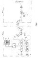
- a mobile telephone apparatus such as that which is shown in FIG. 1 has two separate modules 100 and 200 intended to be distant from each other over relatively short predetermined distances, by example of the order of one meter.
- the first module 100 comprises, on the one hand, all of the transmission means necessary for the transmission of radio frequency signals from the sound signals emitted by the user in front of a microphone 10, with the exception, however, of the amplifier 30 and the transmission antenna 31 which are included in the second module 200.
- the first module 100 further comprises all the means of reception and retrieval for the reception of radiofrequency signals generally issued by a base station of a mobile telephone network and at the return of the corresponding sound signals to a loudspeaker or earphone 18.
- the first module 100 comprises a transmission channel 11 consisting of an encoder 11a and a modulator 11b.
- the microphone 10 is connected to the input of the encoder 11a of the transmission chain 11 to transmit the signals corresponding to the sound signals it receives in order to encode them into signals digital.
- the coding in question here can encompass not only coding sound signals as such but also other operations such as a channel coding, interleaving, encryption and adding information for detection and error correction and for synchronization.
- the result of this coding taken broad sense of the term is a digital signal usually in the form of frames successive information containing all the information to recover the sound signal original.
- the signal digital is a Time Division Multiplexing Access TDMA frame 4.6 ms with eight time slots of 0.57 ms.
- the output of the encoder 11a is connected to the input of the modulator 11b whose function is to modulate a carrier at the frequency f 0 with the digital signals delivered by the encoder 11a.
- the modulation performed by the modulator 12a could be of any digital type (meaning that the modulating signal is digital), such as the types of modulation FSK, PSK, QPSK, MSK, GMSK, etc.
- the modulation operated by the modulator 11b is a modulation of the GMSK (Gaussian Minimum) type Shift Keying).
- the means of reception and restitution consist of a chain of reception 12 itself consists of a demodulator 12a operating on the signals radio frequencies received from an antenna 16 and an inverse type demodulation of the modulation performed by the modulator 11b.
- the demodulated signals are provided at the input of a decoder 12b which performs an inverse decoding of the coding carried out by the encoder 11a.
- the decoded signals are provided, generally after amplification, at a playback means 18 such as a speaker or earphone.
- a management unit 19 controls the encoder 11a and the modulator 11b of the transmission channel 11 and the control of the demodulator 12a and the decoder 12b of the reception channel 12 and their interaction according to the standard set such as the temporal timing of the transmission with respect to reception, management of radio resources according to the protocol received from the infrastructure, etc. She is also connected to a screen E and a keyboard C ensuring a man / machine interface. As will be understood later, the invention requires only a single unit of management 19 which is placed in the first module 100. No management signal is transmitted to the second module 200. This results in the advantage that the transmission channel 11 and the reception chain 12 can be made by a single component 110, such as a processor called DSP (Digital Signal Processor) used in time sharing.
- DSP Digital Signal Processor
- the frequency f 0 of the modulation carrier operated by the modulator 11b is not necessarily the transmission frequency of the mobile phone which will be noted f. Even this frequency f 0 could be zero according to the present invention.
- the radiofrequency signals delivered by the modulator 11b are supplied to frequency changing means 14 whose function is to transpose the initially modulated signals onto a carrier at the frequency f 0 (which can be zero) to a carrier frequency f T.
- the frequency changing means 14 may consist of a mixer with two inputs, one receiving the signals modulated at the frequency fo and the other receiving a sinusoidal signal, by example generated by a suitable oscillator 17 fixed frequency equal to either a frequency f T + f 0 , or a frequency f T - f 0 .
- the resulting signal is a modulated signal corresponding to the modulated input signal but transposed to two carrier frequencies, one being the sum of the frequencies of the input signals, the other being the difference.
- the frequency changing means 14 incorporate a filter to eliminate one of the two resulting frequencies, which is the least practical for the implementation of the invention.
- the signals at the output of the frequency change means 14 are supplied to transmission means 15, constituted in the exemplary embodiment shown, by a appropriate amplifier and an antenna.
- the second module 200 comprises receiving means 26, constituted in this case by an antenna, provided for receive the signals received from the transmitting means 15. Between the transmission means 15 and the reception means 26, is established a transmission link.
- the signals at the output of the reception means 26 are supplied to frequency changing means 29 whose function is to transpose the modulated received signals at the carrier frequency f T into signals modulated at the carrier frequency f.
- the frequency changing means 29 may consist of a mixer with two inputs, one receiving the modulated signals at the carrier frequency f T and the other receiving a sinusoidal signal, by example generated by an appropriate oscillator 25, either at a frequency f + f T equal to the sum of the transmission frequency f and the transposed frequency f T , or at a frequency f - f T f T equal to the difference of the emission frequency f and the transposed frequency f T.
- the means 29 incorporate a filter to eliminate the unwanted frequency.
- the signals at the output of the frequency change means 29 are radiofrequency signals ready to be emitted after amplification.
- it is therefore digital frames TDMA modulating in GMSK a frequency carrier f.
- the second module 200 further comprises an amplifier 30 whose input is connected to the output of the means 29 and whose output attacks a transmitting antenna 31.
- the transmitting means 15 and the receiving means 26 may be of any type provided that they transmit the modulated signals at the transposed frequency f T.
- the link they provide could be wired, optical (eg infra-red), or hertzian.
- the energy radiated by this link is weak compared to that emitted by the antenna 31, so that the invention solves the SAR issues discussed in the preamble of this description.
- the second module 200 that radiates the most energy at high frequency that can be damaging to the tissues of the user's head. Now, this second module 200 the fact that it is possible to move it away from the first module 100 could be brought to a less sensitive user's body location, for example at the waist.
- the transposed frequency f T is advantageously 2.45 GHz, which is a legally available frequency for any type of application.
- the transposed frequency f T could be zero, meaning that the signal at the output of the frequency changing means 14 is identical to the signal modulating at the output of the encoder 11a.
- the advantage of the invention lies in the fact that the modulation process, as well as any transmission process with the exception of amplification, are carried out under the control of the management unit 19 and, therefore, in the first module 100.
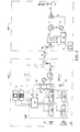
- each phone must, under the command of the base station with which it is in communication, to control its power of emission. It is possible to perform this command in the first module 100 at the chain level 11 under the supervision of the management unit 19, but, for questions of performance, it would be better to perform it at the level of the power amplifier 30. In the embodiment of FIG. 1, this is not possible since the power amplifier 30 is out of control of the management unit 19.
- the first module 100 comprises a multiplexer 13 whose first input receives the coded signal from the modulator 11b and whose second input receives a signal containing the transmission power level information A.
- the second module 200 comprises a demultiplexer 27 provided for outputting on one output the modulated signal at the transposed frequency f T and on the other output the signal containing the transmission power level information, which is supplied to the control input of the amplifier 30.
- the multiplexing operated by the multiplexer 13 could be of any type, for example a time or frequency multiplexing.
- the modulated signals from the modulator 12a are at the frequency f 0 while the power level information signals are modulated at a frequency f 1 in a modulator 32.
- the first are at the frequency f T while the second are at the frequency f 1 - f 0 + f T.
- the demultiplexer 27 will be of the type delivering on a first output the signals at the frequency f T and, on the other output, the signals at the frequency f 1 - fo + f T.
- a demodulator 28 covers the control signal A which is then supplied to the amplifier 30.
- multiplexer 13 could be provided at the output of the means of frequency change 14.
- the frequency of the final transmission carrier f of a mobile phone can be changed, under the command of the base station with which this phone is in communication, frame to frame. Frequency jumps of the carrier are then provided frame to frame.
- the information F concerning the frequency of the transmission carrier which are available at the output of the management unit 19, are transmitted via the transmission means 15 and the means of receiving 26, the first module 100 to the second module 200 where they are provided to a control input of the frequency changing means 29.
- a signal carrying the frequency information of the carrier is multiplexed, for example in the multiplexer 13, with the coded signal from the modulator 11b and, in the second module 200, it is demultiplexed, for example by the demultiplexer 27, the information F being extracted from the signal thus demultiplexed, for example in unit 28 to be then delivered to the control input means 29.
- the signal carrying the information is a signal resulting from the modulation of a carrier at the frequency f 2 by the carrier frequency information.
- the information concerning the transmission carrier frequency may be the number n.
- the frequency changing means 14 perform a transposition of the frequency f 0 to the transposed frequency f T.
- the information n after transmission of the first module 100 to the module 200 via the transmission means 15 and the reception means 26, is available, after demultiplexing by the demultiplexer 27 and demodulation in the demodulator 28, to the input of the frequency changing means 29 which will then effect the change of frequency of the transposed frequency f T to the frequency of the desired carrier: f 0 + ⁇ f x n.
- This can be accomplished by mixing the radio frequency signal at the frequency f T with a sinusoidal signal at the frequency f 0 - f T + ⁇ f xn, for example, delivered by a suitable oscillator whose frequency is controlled by n.
- a channel of signaling is established between the first module 100 and the second module 200.
- channel which can be bidirectional, signaling information S flows for verify the integrity of the connection between the transmitting means 15 and the means of 26.
- These signaling signals S can also be used to establish the connection between the transmitting means 15 and the receiving means 26 so as to ensure that the first module 100 and the second module 200 are paired and that one can not communicate with another of the same type but from another phone according to the present invention.
- these signaling signals are managed by the unit 29 while in the second module 200, they are by a management unit of signaling 35.
- the signaling channel may be set at a frequency offset by a certain amount from the transposed frequency f T , in the first module direction 100 to the second module 200, and by another amount in the other direction.
- the first module 100 establishes and maintains communication with a second module 200.
- a mobile phone according to the present invention can be associated with at least one another module identical to its second module 200 to constitute a system of mobile phone.
Abstract
Description
La présente invention concerne un téléphone mobile du type à deux modules distincts.The present invention relates to a mobile phone of the two-module type distinct.
On sait qu'un téléphone mobile peut émettre des rayonnements électromagnétiques susceptibles d'agir sur les tissus à proximité, notamment ceux de la tête de l'utilisateur lorsque le téléphone est placé contre son oreille alors qu'il est en communication. On a défini une grandeur objective de référence liée à la puissance maximale pouvant être absorbée par les tissus corporels et qu'il est souhaitable qu'un téléphone mobile ne dépasse pas. Cette grandeur est appelée débit d'absorption spécifique ou plus communément SAR (Specific Absorption Rate). Elle fait l'objet de valeurs normalisées que les constructeurs sont tenus de ne pas dépasser. We know that a mobile phone can emit radiation electromagnetic properties that may affect nearby tissues, including the head of the user when the phone is placed against his ear while he is in communication. An objective reference quantity linked to the power has been defined body tissue and that it is desirable that a mobile phone does not go over. This quantity is called absorption rate specific or more commonly SAR (Specific Absorption Rate). It is the subject of standardized values that manufacturers are required not to exceed.
Différentes méthodes ont déjà été proposées pour résoudre, au moins en partie, ce problème lié à une valeur excessive du SAR. Parmi celles-ci, on peut citer une méthode qui consiste à éloigner la partie rayonnante du téléphone mobile d'une autre partie de ce téléphone qui elle est nécessairement portée contre la tête de l'utilisateur. Une telle solution est par exemple celle qui est décrite dans le document de brevet GB-A-2 364 846. Le téléphone mobile décrit dans ce document est divisé en deux modules distincts dont l'un, le module émetteur, peut être éloigné de la tête de l'utilisateur. En l'occurrence, le premier module comporte, d'une part, l'ensemble des éléments servant au traitement des signaux radiofréquences reçus, à savoir une antenne de réception, un amplificateur radiofréquence, un démodulateur du type GMSK, un décodeur de signaux numériques en signaux audio et un haut-parleur et, d'autre part, un microphone. Quant au second module, il comporte l'ensemble des éléments servant au traitement des signaux radiofréquences à émettre, à savoir un codeur de signaux audio en signaux numériques, un modulateur du type GMSK, un amplificateur radiofréquence et une antenne d'émission, à l'exception du microphone.Various methods have already been proposed to solve, at least in part, this problem is related to an excessive value of the SAR. Among these, we can mention a method of moving the radiating part of the mobile phone away from another part of this phone that is necessarily worn against the user's head. Such a solution is for example that which is described in the patent document GB-A-2 364 846. The mobile phone described in this document is divided in two separate modules, one of which, the transmitter module, can be moved away from the head of the user. In this case, the first module includes, on the one hand, all the elements for the processing of the received radio frequency signals, namely a receiving antenna, a radio frequency amplifier, a demodulator of the type GMSK, a decoder of digital signals into audio signals and a loudspeaker and, on the other hand, a microphone. As for the second module, it includes all the elements for the processing of radio frequency signals to be transmitted, namely a encoder of audio signals into digital signals, a modulator of the GMSK type, a radio frequency amplifier and a transmitting antenna, except the microphone.
Le premier et le second modules sont reliés l'un à l'autre par un lien radio-fréquence à basse fréquence de manière que les signaux audio générés par le microphone du premier module puissent être transmis au codeur du second module. Pour ce faire, le premier module comporte un émetteur radio-fréquence à basse fréquence auquel sont appliqués les signaux audio du microphone alors que le second module comporte un récepteur correspondant à cet émetteur qui est relié à l'entrée du codeur pour lui transmettre les signaux audio qu'il a reçus de l'émetteur.The first and the second modules are connected to each other by a radio frequency link low frequency so that the audio signals generated by the microphone of the first module can be transmitted to the encoder of the second module. To do this, the first module comprises a low-frequency radio-frequency transmitter the frequency at which the audio signals of the microphone are applied, whereas the second module has a receiver corresponding to this transmitter which is connected to the input of the encoder to transmit the audio signals received from the transmitter.
Dans tout téléphone mobile, il y a une interaction permanente entre la chaíne de réception et la chaíne d'émission. En effet, les signaux émis doivent être positionnés dans le temps avec précision par rapport aux signaux reçus. De plus, d'une manière générale, la plupart des fonctions d'émission d'un téléphone mobile est commandée par un protocole de signalisation reçu de l'infrastructure sur la voie réception (désignation du canal à employer pour l'émission, télécommande de puissance, etc.).In any mobile phone, there is a permanent interaction between the chain of reception and the transmission channel. Indeed, the emitted signals must be positioned in time precisely with respect to the signals received. Moreover, in a way Generally speaking, most of the transmitting functions of a mobile phone are controlled by a signaling protocol received from the infrastructure on the reception channel (designation of the channel to be used for transmission, power remote control, etc.).
Il s'ensuit que la mise en oeuvre de cette contrainte d'interaction entre chaíne d'émission et chaíne de réception à l'architecture proposée dans le document GB-A-2 364 846 peut s'avérer complexe rendant la solution qui y est proposée rédhibitoire. It follows that the implementation of this interaction constraint between chain transmission and reception chain to the architecture proposed in the document GB-A-2 364 846 can be complex making the solution proposed therein crippling.
Le but de la présente invention est de proposer un téléphone mobile qui est constitué de deux modules distincts, dont l'un peut être éloigné de la tête de l'utilisateur lors d'une communication, reprenant ainsi le concept notamment décrit dans le document GB-A-2 364 846 en tant que solution au problème d'un SAR trop élevé, mais dont l'architecture soit telle que l'interaction de la chaíne d'émission et de la chaíne de réception soit relativement simple à mettre en oeuvre.The purpose of the present invention is to propose a mobile phone which is consisting of two separate modules, one of which may be distant from the head of the user during a communication, thus taking up the concept described in particular in GB-A-2 364 846 as a solution to the problem of a SAR too much high, but whose architecture is such that the interaction of the transmission and the reception chain is relatively simple to implement.
A cet effet, un téléphone mobile selon la présente invention est du type comportant une chaíne d'émission prévue pour recevoir les signaux d'un microphone et pour délivrer des signaux correspondants modulés sur une porteuse à une fréquence f0, un amplificateur pour attaquer une antenne d'émission pour émettre lesdits signaux modulés en tant que signaux radiofréquences, et une chaíne de réception pour la réception et la restitution des signaux radiofréquences reçus, ladite chaíne d'émission et ladite chaíne de réception étant pilotées par une unité de gestion, ledit téléphone mobile comprenant deux modules distincts.For this purpose, a mobile phone according to the present invention is of the type comprising a transmission channel intended to receive the signals of a microphone and to deliver corresponding signals modulated on a carrier at a frequency f 0 , an amplifier for driving a signal. transmitting antenna for transmitting said modulated signals as radiofrequency signals, and a reception channel for receiving and retrieving the received radio frequency signals, said transmission system and said reception channel being controlled by a management unit, said mobile phone comprising two separate modules.
Selon une première caractéristique avantageuse de la présente invention, ledit téléphone mobile est caractérisé en ce que :
- la chaíne d'émission, la chaíne de réception et ladite unité de gestion sont
montées dans un desdits modules, dit premier module, alors que ledit amplificateur et
ladite antenne d'émission sont montés dans l'autre module, dit second module,
et en ce que - ledit premier module comporte en outre des moyens de changement de fréquence pour transposer la fréquence de la porteuse des signaux issus de la chaíne d'émission et des moyens d'émission desdits signaux à fréquence de porteuse transposée, et
- ledit second module comporte des moyens de réception desdits signaux émis par lesdits moyens d'émission et des moyens de changement de fréquence pour transposer la fréquence desdits signaux ainsi reçus sur la fréquence de la porteuse des signaux radiofréquences.
- the transmission channel, the reception channel and the said management unit are mounted in one of the said modules, called the first module, while the said amplifier and the said transmitting antenna are mounted in the other module, called the second module,
and in that - said first module further comprises frequency changing means for transposing the frequency of the carrier signals from the transmission channel and means for transmitting said transposed carrier frequency signals, and
- said second module comprises means for receiving said signals emitted by said transmitting means and frequency changing means for transposing the frequency of said signals thus received onto the frequency of the carrier of the radio frequency signals.
Selon une autre caractéristique de l'invention, les moyens d'émission et les moyens de réception assurent une liaison filaire, optique ou hertzienne.According to another characteristic of the invention, the transmission means and the receiving means provide a wired link, optical or radio.
Selon une autre caractéristique de l'invention, la fréquence transposée obtenue par les moyens de changement de fréquence dudit premier module est nulle. Mais, selon une autre caractéristique de l'invention, les moyens d'émission et les moyens de réception assurent une liaison hertzienne à une fréquence de 2,45 GHz.According to another characteristic of the invention, the transposed frequency obtained by the frequency changing means of said first module is zero. But, according to another characteristic of the invention, the transmission means and the means of receive a radio link at a frequency of 2.45 GHz.
Selon une autre caractéristique de l'invention, des informations concernant le niveau de puissance d'émission dudit téléphone sont transmises, via lesdits moyens d'émission et lesdits moyens de réception, dudit premier module audit second module où elles sont fournies à une entrée de commande dudit amplificateur pour commander son niveau de puissance de sortie.According to another characteristic of the invention, information concerning the transmission power level of said telephone are transmitted via said means transmission and reception means, from said first module to said second module where they are supplied to a control input of said amplifier for controlling its output power level.
De même, selon une autre caractéristique de l'invention, des informations concernant la fréquence de la porteuse d'émission dudit téléphone sont transmises, via lesdits moyens d'émission et lesdits moyens de réception, dudit premier module audit second module où elles sont fournies à une entrée de commande des moyens de changement de fréquence.Likewise, according to another characteristic of the invention, information concerning the frequency of the transmission carrier of said telephone are transmitted via said transmitting means and said receiving means, of said first auditing module second module where they are provided to a control input means of frequency change.
Selon une autre caractéristique de l'invention, ledit premier module comporte un multiplexeur prévu pour multiplexer des signaux portant lesdites informations avec les signaux à fréquence transposée et ledit second module comporte un démultiplexeur pour délivrer les signaux à fréquence transposée, d'une part, et les signaux portant lesdites informations, d'autre part.According to another characteristic of the invention, said first module comprises a multiplexer provided for multiplexing signals carrying said information with the transposed frequency signals and said second module comprises a demultiplexer for delivering the transposed frequency signals, on the one hand, and the signals carrying said information, on the other hand.
Selon une autre caractéristique de l'invention, lesdites informations modulent une porteuse pour former ainsi lesdits signaux portant lesdites informations, ledit multiplexeur et ledit démultiplexeur étant du type à division de fréquence.According to another characteristic of the invention, said information modulates a carrier to thereby form said signals carrying said information, said multiplexer and said demultiplexer being of the frequency division type.
Selon une autre caractéristique de l'invention, un canal de signalisation est prévu entre ledit premier module et ledit second module sur lequel circulent des signaux de signalisation pour établir la liaison entre les moyens d'émission dudit premier module et les moyens de réception dudit second module de manière à assurer qu'ils sont appariés.According to another characteristic of the invention, a signaling channel is provided between said first module and said second module on which signaling for establishing the connection between the transmission means of said first module and the receiving means of said second module so as to ensure that they are matched.
Selon une autre caractéristique de l'invention, un canal de signalisation est prévu entre ledit premier module et ledit second module sur lequel circulent des signaux de signalisation pour vérifier l'intégrité de la liaison entre les moyens d'émission dudit premier module et les moyens de réception dudit second module.According to another characteristic of the invention, a signaling channel is provided between said first module and said second module on which signaling to verify the integrity of the connection between the transmission means of said first module and the means for receiving said second module.
La présente invention concerne également un système de téléphone mobile qui est caractérisé en ce qu'il comporte un téléphone mobile comme défini précédemment et au moins un autre module identique audit second module dudit téléphone mobile.The present invention also relates to a mobile telephone system which is characterized in that it comprises a mobile phone as defined above and at least one other module identical to said second module of said mobile phone.
Les caractéristiques de l'invention mentionnées ci-dessus, ainsi que d'autres,
apparaítront plus clairement à la lecture de la description suivante d'un exemple de
réalisation, ladite description étant faite en relation avec les dessins joints, parmi
lesquels:
Un appareil de téléphonie mobile selon l'invention tel que celui qui est
représenté à la Fig. 1 comporte deux modules distincts 100 et 200 prévus pour être
éloignés l'un de l'autre sur des distances prédéterminées relativement courtes, par
exemple de l'ordre d'un mètre.A mobile telephone apparatus according to the invention such as that which is
shown in FIG. 1 has two
Le premier module 100 comporte, d'une part, l'ensemble des moyens d'émission
nécessaires à l'émission de signaux radiofréquences à partir des signaux sonores émis
par l'utilisateur devant un microphone 10, à l'exception cependant de l'amplificateur
de puissance 30 et de l'antenne d'émission 31 qui eux sont compris dans le second
module 200. Le premier module 100 comporte en outre l'ensemble des moyens de
réception et de restitution servant à la réception des signaux radiofréquences
généralement émis par une station de base d'un réseau de téléphonie mobile et à la
restitution des signaux sonores correspondants sur un haut-parleur ou un écouteur 18. The
Plus précisément, le premier module 100 comporte une chaíne d'émission 11
constituée d'un codeur 11a et d'un modulateur 11b. Le microphone 10 est relié à
l'entrée du codeur 11a de la chaíne d'émission 11 pour lui transmettre les signaux
électriques correspondant aux signaux sonores qu'il reçoit afin de les coder en signaux
numériques. Le codage dont il est question ici peut englober non seulement le codage
des signaux sonores proprement dit mais également d'autres opérations telles qu'un
codage canal, un entrelacement, un cryptage et l'ajout d'informations pour la détection
et la correction d'erreurs et pour la synchronisation. Le résultat de ce codage pris au
sens large du terme est un signal numérique généralement sous forme de trames
successives contenant toutes les informations pour recouvrer le signal sonore
d'origine.More specifically, the
Dans le cas d'un téléphone mobile conforme au standard GSM, le signal numérique est une trame TDMA (Time Division Multiplexage Access) de durée 4,6 ms comportant huit intervalles de temps de 0,57 ms.In the case of a mobile phone conforming to the GSM standard, the signal digital is a Time Division Multiplexing Access TDMA frame 4.6 ms with eight time slots of 0.57 ms.
La sortie du codeur 11a est reliée à l'entrée du modulateur 11b qui a pour
fonction de moduler une porteuse à la fréquence f0 avec les signaux numériques
délivrés par le codeur 11a. Dans le cadre de la présente invention, la modulation
effectuée par le modulateur 12a pourrait être de tout type numérique (signifiant que le
signal modulant est numérique), comme les types de modulations FSK, PSK, QPSK,
MSK, GMSK, etc.The output of the
Dans le cas d'un téléphone mobile conforme au standard GSM, la modulation
opérée par le modulateur 11b est une modulation du type GMSK (Gaussian Minimum
Shift Keying).In the case of a mobile phone conforming to the GSM standard, the modulation
operated by the
Les moyens de réception et de restitution sont constitués d'une chaíne de
réception 12 elle-même constituée d'un démodulateur 12a opérant sur les signaux
radiofréquences reçus d'une antenne 16 et une démodulation de type inverse de la
modulation effectuée par le modulateur 11b. Les signaux démodulés sont fournis à
l'entrée d'un décodeur 12b qui exécute un décodage inverse du codage effectué par le
codeur 11a. Les signaux décodés sont fournis, généralement après amplification, à un
moyen de restitution 18 tel qu'un haut-parleur ou un écouteur.The means of reception and restitution consist of a chain of
Une unité de gestion 19 assure le contrôle du codeur 11a et du modulateur 11 b
de la chaíne d'émission 11 et le contrôle du démodulateur 12a et du décodeur 12b de
la chaíne de réception 12 ainsi que leur interaction conforme au standard mis en
oeuvre, tel que le calage temporel de l'émission par rapport à la réception, gestion des
ressources radio selon le protocole reçu de l'infrastructure, etc. Elle est également
reliée à un écran E et un clavier C assurant ainsi une interface homme/machine.
Comme on le comprendra par la suite, l'invention ne nécessite qu'une unique unité de
gestion 19 laquelle est placée dans le premier module 100. Aucun signal de gestion
n'est transmis au second module 200. Il en résulte l'avantage que la chaíne émission 11
et la chaíne réception 12 peuvent être réalisées par un unique composant 110, tel qu'un
processeur dit DSP (Digital Signal Processor) utilisé en partage de temps.A
Comme on le comprendra par la suite, la fréquence f0 de la porteuse de
modulation opérée par le modulateur 11b n'est pas nécessairement la fréquence
d'émission du téléphone mobile qui, elle sera notée f. Même, cette fréquence f0
pourrait être nulle selon la présente invention.As will be understood later, the frequency f 0 of the modulation carrier operated by the
Dans un premier mode de réalisation, les signaux radiofréquences délivrés par le
modulateur 11b sont fournis à des moyens de changement de fréquence 14 dont la
fonction est de transposer les signaux modulés initialement sur une porteuse à la
fréquence f0 (qui peut être nulle) à une fréquence porteuse fT. Comme il est connu
dans le domaine de la technique, les moyens de changement de fréquences 14 peuvent
être constitués d'un mélangeur à deux entrées, l'une recevant les signaux modulés à la
fréquence fo et l'autre recevant un signal sinusoïdal, par exemple généré par un
oscillateur 17 approprié à fréquence fixe égale soit à une fréquence fT + f0, soit à une
fréquence fT - f0. Le signal résultant est un signal modulé correspondant au signal
modulé d'entrée mais transposé à deux fréquences porteuses, l'une étant la somme des
fréquences des signaux d'entrée, l'autre étant la différence. Les moyens de changement
de fréquence 14 incorporent un filtre pour éliminer l'une des deux fréquences
résultantes, celle qui est la moins pratique pour la mise en oeuvre de l'invention.In a first embodiment, the radiofrequency signals delivered by the
Les signaux en sortie des moyens de changement de fréquence 14 sont fournis à des moyens d'émission 15, constitués dans l'exemple de réalisation représenté, par un amplificateur approprié et une antenne.The signals at the output of the frequency change means 14 are supplied to transmission means 15, constituted in the exemplary embodiment shown, by a appropriate amplifier and an antenna.
Selon le premier mode de réalisation de la présente invention, le second module
200 comporte des moyens de réception 26, constitués ici d'une antenne, prévus pour
recevoir les signaux reçus des moyens d'émission 15. Entre les moyens d'émission 15
et les moyens de réception 26, est établi un lien de transmission.According to the first embodiment of the present invention, the
Les signaux en sortie des moyens de réception 26 sont fournis à des moyens de
changement de fréquence 29 dont la fonction est de transposer les signaux reçus
modulés à la fréquence porteuse fT en des signaux modulés à la fréquence porteuse f.
Similairement aux moyens de changement de fréquence 14, les moyens de
changement de fréquence 29 peuvent être constitués d'un mélangeur à deux entrées,
l'une recevant les signaux modulés à la fréquence porteuse fT et l'autre recevant un
signal sinusoïdal, par exemple généré par un oscillateur 25 approprié, soit à une
fréquence f + fT égale à la somme de la fréquence d'émission f et de la fréquence
transposée fT, soit à une fréquence f - fT fT égale à la différence de la fréquence
d'émission f et de la fréquence transposée fT. A l'instar des moyens de changement de
fréquence 14, les moyens 29 incorporent un filtre pour éliminer la fréquence
indésirable.The signals at the output of the reception means 26 are supplied to frequency changing means 29 whose function is to transpose the modulated received signals at the carrier frequency f T into signals modulated at the carrier frequency f. Similarly to the frequency changing means 14, the frequency changing means 29 may consist of a mixer with two inputs, one receiving the modulated signals at the carrier frequency f T and the other receiving a sinusoidal signal, by example generated by an
On notera que les signaux en sortie des moyens de changement de fréquence 29 sont des signaux radiofréquences prêts à être émis après amplification. Dans le cas d'un téléphone conforme au standard GSM, il s'agit donc de trames numériques TDMA modulant en GMSK une porteuse de fréquence f.It will be noted that the signals at the output of the frequency change means 29 are radiofrequency signals ready to be emitted after amplification. In the case of a GSM-compliant phone, it is therefore digital frames TDMA modulating in GMSK a frequency carrier f.
Le second module 200 comporte encore un amplificateur 30 dont l'entrée est
reliée à la sortie des moyens 29 et dont la sortie attaque une antenne d'émission 31.The
Les moyens d'émission 15 et les moyens de réception 26 peuvent être de tout type dès lors qu'ils assurent la transmission des signaux modulés à la fréquence transposée fT. La liaison qu'ils assurent pourrait être filaire, optique (par exemple infra-rouge), ou hertzienne.The transmitting means 15 and the receiving means 26 may be of any type provided that they transmit the modulated signals at the transposed frequency f T. The link they provide could be wired, optical (eg infra-red), or hertzian.
Même dans ce dernier cas, l'énergie qui est rayonnée par cette liaison est faible
comparée à celle qui est émise par l'antenne 31, si bien que l'invention résout les
problèmes liés au SAR évoqués dans le préambule de la présente description. En effet,
c'est le second module 200 qui rayonne le plus d'énergie à haute-fréquence pouvant
être dommageable pour les tissus de la tête de l'utilisateur. Or, ce second module 200
du fait qu'il est possible de l'éloigner du premier module 100 pourrait être porté à un
endroit de corps de l'utilisateur moins sensible, par exemple à la ceinture. Even in the latter case, the energy radiated by this link is weak
compared to that emitted by the
Dans le cas où les moyens d'émission 15 et les moyens de réception 26 assurent une liaison hertzienne, la fréquence transposée fT est avantageusement 2,45 GHz, qui est une fréquence légalement disponible pour tout type d'application.In the case where the transmitting means 15 and the receiving means 26 provide a radio link, the transposed frequency f T is advantageously 2.45 GHz, which is a legally available frequency for any type of application.
On notera que la fréquence transposée fT pourrait être nulle, signifiant que le
signal en sortie des moyens de changement de fréquence 14 est identique au signal
modulant en sortie du codeur 11a. Même dans ce cas, l'avantage de l'invention réside
dans le fait que le processus de modulation, ainsi que tout processus d'émission à
l'exception de l'amplification, sont effectués sous le contrôle de l'unité de gestion 19
et, par conséquent, dans le premier module 100.It will be noted that the transposed frequency f T could be zero, meaning that the signal at the output of the frequency changing means 14 is identical to the signal modulating at the output of the
Généralement, dans un système de téléphonie mobile, suite à un processus qui
n'est pas décrit ici, chaque téléphone doit, sous la commande de la station de base avec
laquelle il est en communication, contrôler sa puissance d'émission. Il est possible
d'effectuer cette commande dans le premier module 100 au niveau de la chaíne
d'émission 11 sous contrôle de l'unité de gestion 19, mais, pour des questions de
rendement, il serait préférable de l'effectuer au niveau de l'amplificateur de puissance
final 30. Or, dans le mode de réalisation de la Fig. 1, ceci n'est pas possible puisque
l'amplificateur de puissance 30 est hors du contrôle de l'unité de gestion 19.Generally, in a mobile phone system, following a process that
is not described here, each phone must, under the command of the base station with
which it is in communication, to control its power of emission. It is possible
to perform this command in the
C'est pourquoi, selon le second mode de réalisation de la présente invention qui
est représenté à la Fig. 2 (dans laquelle les mêmes éléments que ceux déjà présents à
la Fig. 1 portent les mêmes références), des informations concernant le niveau de
puissance d'émission, qui sont disponibles à la sortie de l'unité de gestion 19, sont
transmises, via les moyens d'émission 15 et les moyens de réception 26, du premier
module 100 au second module 200 où elles sont fournies à une entrée de commande
de l'amplificateur 30 pour commander son niveau de sortie.Therefore, according to the second embodiment of the present invention which
is shown in FIG. 2 (in which the same elements as those already present at
FIG. 1 have the same references), information concerning the level of
transmission power, which are available at the output of the
Plus précisément, le premier module 100 comporte un multiplexeur 13 dont une
première entrée reçoit le signal codé issu du modulateur 11b et dont la seconde entrée
reçoit un signal contenant l'information de niveau de puissance d'émission A. Quant
au second module 200, il comporte un démultiplexeur 27 prévu pour délivrer sur une
sortie le signal modulé à la fréquence transposée fT et sur l'autre sortie le signal
contenant l'information de niveau de puissance d'émission, lequel est fourni à l'entrée
de commande de l'amplificateur 30. More specifically, the
Le multiplexage opéré par le multiplexeur 13 pourrait être de tout type, par
exemple un multiplexage temporel ou fréquentiel.The multiplexing operated by the
Dans le cas d'un multiplexage fréquentiel, les signaux modulés issus du
modulateur 12a sont à la fréquence f0 alors que les signaux d'information de niveau de
puissance sont modulés à une fréquence f1 dans un modulateur 32. Après changement
de fréquence, les premiers sont à la fréquence fT alors que les seconds sont à la
fréquence f1 - f0 + fT. Le démultiplexeur 27 sera du type délivrant sur une première
sortie les signaux à la fréquence fT et, sur l'autre sortie, les signaux à la fréquence
f1 - fo + fT. Un démodulateur 28 assure le recouvrement du signal de commande A qui
est alors fourni à l'amplificateur 30.In the case of a frequency multiplexing, the modulated signals from the
On notera que le multiplexeur 13 pourrait être prévu à la sortie des moyens de
changement de fréquence 14.It will be noted that the
Selon certains standards de téléphonie mobile, ou selon des modes de fonctionnement de ces standards, la fréquence de la porteuse d'émission finale f d'un téléphone mobile peut être modifiée, sous la commande de la station de base avec laquelle ce téléphone est en communication, trame à trame. Des sauts de la fréquence de la porteuse sont alors prévus trame à trame.According to certain standards of mobile telephony, or according to modes of operation of these standards, the frequency of the final transmission carrier f of a mobile phone can be changed, under the command of the base station with which this phone is in communication, frame to frame. Frequency jumps of the carrier are then provided frame to frame.
Selon un troisième mode de réalisation de la présente invention, les informations
F concernant la fréquence de la porteuse d'émission, qui sont disponibles à la sortie de
l'unité de gestion 19, sont transmises, via les moyens d'émission 15 et les moyens de
réception 26, du premier module 100 au second module 200 où elles sont fournies à
une entrée de commande des moyens de changement de fréquence 29.According to a third embodiment of the present invention, the information
F concerning the frequency of the transmission carrier, which are available at the output of
the
Plus précisément, dans le premier module 100, un signal portant les
informations F de fréquence de la porteuse est multiplexé, par exemple dans le
multiplexeur 13, avec le signal codé issu du modulateur 11b et, dans le second module
200, il est démultiplexé, par exemple par le démultiplexeur 27, les informations F
étant extraites du signal ainsi démultiplexé, par exemple dans l'unité 28 pour être
ensuite délivrées à l'entrée de commande des moyens 29.More specifically, in the
Par exemple, selon le mode de réalisation représenté, le signal portant les informations est un signal résultant de la modulation d'une porteuse à la fréquence f2 par les informations de fréquence de porteuse. For example, according to the embodiment shown, the signal carrying the information is a signal resulting from the modulation of a carrier at the frequency f 2 by the carrier frequency information.
Si la fréquence de la porteuse d'émission doit être de f0 + Δf x n, Δf désignant la
largeur d'un saut de fréquence unitaire et n un indice de saut, l'information concernant
la fréquence de porteuse d'émission peut être le chiffre n. A l'instar des modes de
réalisation précédents, les moyens de changement de fréquence 14 effectuent une
transposition de la fréquence f0 à la fréquence transposée fT. L'information n, après
transmission du premier module 100 au module 200 par l'intermédiaire des moyens
d'émission 15 et des moyens de réception 26, est disponible, après démultiplexage par
le démultiplexeur 27 et démodulation dans le démodulateur 28, à l'entrée des moyens
de changement de fréquence 29 lesquels effectueront alors le changement de
fréquence de la fréquence transposée fT à la fréquence de la porteuse souhaitée : f0 +
Δf x n. Cela peut être accompli par le mélange du signal radiofréquence à la fréquence
fT à un signal sinusoïdal à la fréquence f0 - fT + Δf x n, par exemple délivré par un
oscillateur 25 approprié dont la fréquence est commandée par n.If the frequency of the transmission carrier must be f 0 + Δf xn, where Δf denotes the width of a unitary frequency jump and n is a hop index, the information concerning the transmission carrier frequency may be the number n. Like the previous embodiments, the frequency changing means 14 perform a transposition of the frequency f 0 to the transposed frequency f T. The information n, after transmission of the
Dans un autre mode de réalisation de la présente invention, un canal de
signalisation est établi entre le premier module 100 et le second module 200. Sur ce
canal, qui peut être bidirectionnel, des informations de signalisation S circulent pour
vérifier l'intégrité de la liaison entre les moyens d'émission 15 et les moyens de
réception 26. Ces signaux de signalisation S peuvent également servir à établir la
liaison entre les moyens d'émission 15 et les moyens de réception 26 de manière à
assurer que le premier module 100 et le second module 200 sont appariés et que l'un
ne puisse pas communiquer avec un autre du même type mais d'un autre téléphone
selon la présente invention.In another embodiment of the present invention, a channel of
signaling is established between the
Dans le premier module 100, ces signaux de signalisation sont gérés par l'unité
29 alors que dans le second module 200, ils le sont par une unité de gestion de
signalisation 35.In the
Le canal de signalisation peut être établi à une fréquence décalée d'une certaine
quantité par rapport à la fréquence transposée fT, dans le sens premier module 100
vers second module 200, et d'une autre quantité dans l'autre sens.The signaling channel may be set at a frequency offset by a certain amount from the transposed frequency f T , in the
On comprendra, qu'au moyen de ces signaux de signalisation S, le premier
module 100 établit et maintient une communication avec un second module 200.It will be understood that by means of these signaling signals S, the
On notera qu'un même module 100 pourrait communiquer avec plusieurs
seconds modules 200, lesquels pourraient être respectivement placés à divers endroits
d'utilisation, tels qu'un endroit de la maison de l'utilisation, de sa voiture ou de son
bureau, dès lors que les premier module et second module sont à portée l'un de l'autre.
Ainsi, un téléphone mobile selon la présente invention peut être associé à au moins un
autre module identique à son second module 200 pour constituer un système de
téléphone mobile.It will be noted that the
Claims (12)
caractérisé en ce que :
et en ce que
characterized in that
and in that
Applications Claiming Priority (2)
| Application Number | Priority Date | Filing Date | Title |
|---|---|---|---|
| FR0400277 | 2004-01-13 | ||
| FR0400277A FR2865093B1 (en) | 2004-01-13 | 2004-01-13 | MOBILE TELEPHONE OF THE TYPE WITH TWO SEPARATE MODULES |
Publications (2)
| Publication Number | Publication Date |
|---|---|
| EP1555794A1 true EP1555794A1 (en) | 2005-07-20 |
| EP1555794B1 EP1555794B1 (en) | 2008-03-19 |
Family
ID=34610763
Family Applications (1)
| Application Number | Title | Priority Date | Filing Date |
|---|---|---|---|
| EP20050290037 Expired - Fee Related EP1555794B1 (en) | 2004-01-13 | 2005-01-06 | Mobile telephone of the type with two distinct modules |
Country Status (3)
| Country | Link |
|---|---|
| EP (1) | EP1555794B1 (en) |
| DE (1) | DE602005005368T2 (en) |
| FR (1) | FR2865093B1 (en) |
Citations (5)
| Publication number | Priority date | Publication date | Assignee | Title |
|---|---|---|---|---|
| EP0840465A2 (en) * | 1996-10-31 | 1998-05-06 | Nokia Mobile Phones Ltd. | User interface for mobile telephone |
| GB2340691A (en) * | 1998-08-15 | 2000-02-23 | Univ Bristol | Mobile phone arrangement for limiting high frequency radiation exposure |
| WO2000056051A1 (en) * | 1999-03-12 | 2000-09-21 | Mti, Inc. | Cellular telephone with reduced radiation exposure |
| DE10237098A1 (en) * | 2002-05-29 | 2003-12-24 | Lite On Technology Co | Mobile phone has separable user interface and network parts with optional Bluetooth or connector links |
| WO2004025929A2 (en) * | 2002-09-09 | 2004-03-25 | Vertu Ltd | Cellular radio telephone |
-
2004
- 2004-01-13 FR FR0400277A patent/FR2865093B1/en not_active Expired - Fee Related
-
2005
- 2005-01-06 DE DE200560005368 patent/DE602005005368T2/en active Active
- 2005-01-06 EP EP20050290037 patent/EP1555794B1/en not_active Expired - Fee Related
Patent Citations (5)
| Publication number | Priority date | Publication date | Assignee | Title |
|---|---|---|---|---|
| EP0840465A2 (en) * | 1996-10-31 | 1998-05-06 | Nokia Mobile Phones Ltd. | User interface for mobile telephone |
| GB2340691A (en) * | 1998-08-15 | 2000-02-23 | Univ Bristol | Mobile phone arrangement for limiting high frequency radiation exposure |
| WO2000056051A1 (en) * | 1999-03-12 | 2000-09-21 | Mti, Inc. | Cellular telephone with reduced radiation exposure |
| DE10237098A1 (en) * | 2002-05-29 | 2003-12-24 | Lite On Technology Co | Mobile phone has separable user interface and network parts with optional Bluetooth or connector links |
| WO2004025929A2 (en) * | 2002-09-09 | 2004-03-25 | Vertu Ltd | Cellular radio telephone |
Also Published As
| Publication number | Publication date |
|---|---|
| EP1555794B1 (en) | 2008-03-19 |
| FR2865093A1 (en) | 2005-07-15 |
| DE602005005368T2 (en) | 2009-04-23 |
| FR2865093B1 (en) | 2006-03-10 |
| DE602005005368D1 (en) | 2008-04-30 |
Similar Documents
| Publication | Publication Date | Title |
|---|---|---|
| Cho et al. | Trans-atlantic field trial using high spectral efficiency probabilistically shaped 64-QAM and single-carrier real-time 250-Gb/s 16-QAM | |
| EP0610988B1 (en) | Multi-user spread spectrum communication system | |
| US7620328B2 (en) | Multi-wavelength optical CDMA with differential encoding and bipolar differential detection | |
| EP0631400B1 (en) | Portable transmitting and receiving device for two-mode digital signals | |
| EP1070401A1 (en) | Cellular radio signal with additional channel assigned to downlink, corresponding method, system and base station | |
| EP0545783A1 (en) | Half-duplex modem for GSM radio telephone network | |
| FR2667208A1 (en) | METHOD AND SYSTEM FOR IDENTIFYING CONTROL CHANNEL TIME CRANES IN A CELLULAR RADIOTELEPHONE NETWORK. | |
| EP2400723A1 (en) | Data transfer management method using a Bluetooth type interface | |
| EP0095959A1 (en) | Frequency hopping radiocommunication system | |
| EP0660559A1 (en) | Multicarrier frequency-hopping communication system | |
| EP0314101A1 (en) | Radiofrequency-optical transmission system, especially in the field of satellite communications | |
| FR2667747A1 (en) | TRANSMISSION SYSTEM COMPRISING A PLURALITY OF SUBSCRIBER DEVICES. | |
| FR2773620A1 (en) | Optical telecommunications terminal station | |
| EP0961264B1 (en) | Emitting/receiving device for the selection of a source coder and methods used therein | |
| EP1307994B1 (en) | Secure identification method between two radiofrequency network appliances | |
| EP1555794B1 (en) | Mobile telephone of the type with two distinct modules | |
| EP1161054B1 (en) | Transmission process with signal processing between two distinct transmission/reception interfaces | |
| WO1999037108A1 (en) | Radiocommunication equipment with secure communication mode and extension unit forming part of such an equipment | |
| EP0305261B1 (en) | Method for quickly synchronizing vocoders coupled by enciphering and deciphering apparatuses | |
| Allimuthu et al. | WAVE-BASED SIGNAL SECURITY AND PRIVACY STUDIES USING AUTOMATIC HIGH-BIT-RATE OPTICAL COMMUNICATIONS WITH QUANTUM CRYPTOGRAPHIC | |
| Perić et al. | An experiment with real-time data transmission over global scale mobile voice channel | |
| EP0725544B1 (en) | System for displacing a television signal scrambler | |
| JP2001308828A (en) | Method and device for arranging confidentiality in radio equipment | |
| WO2024027983A1 (en) | Method, implemented by an air or space device, for communicating with at least one terminal, and associated device, system and computer program | |
| WO2023227791A1 (en) | Method for discovering a radio communication network and filtering an audio signal allowing group communication |
Legal Events
| Date | Code | Title | Description |
|---|---|---|---|
| PUAI | Public reference made under article 153(3) epc to a published international application that has entered the european phase |
Free format text: ORIGINAL CODE: 0009012 |
|
| AK | Designated contracting states |
Kind code of ref document: A1 Designated state(s): AT BE BG CH CY CZ DE DK EE ES FI FR GB GR HU IE IS IT LI LT LU MC NL PL PT RO SE SI SK TR |
|
| AX | Request for extension of the european patent |
Extension state: AL BA HR LV MK YU |
|
| 17P | Request for examination filed |
Effective date: 20050806 |
|
| AKX | Designation fees paid |
Designated state(s): DE GB |
|
| RAP1 | Party data changed (applicant data changed or rights of an application transferred) |
Owner name: SAGEM COMMUNICATION |
|
| 17Q | First examination report despatched |
Effective date: 20050923 |
|
| GRAP | Despatch of communication of intention to grant a patent |
Free format text: ORIGINAL CODE: EPIDOSNIGR1 |
|
| GRAS | Grant fee paid |
Free format text: ORIGINAL CODE: EPIDOSNIGR3 |
|
| GRAA | (expected) grant |
Free format text: ORIGINAL CODE: 0009210 |
|
| AK | Designated contracting states |
Kind code of ref document: B1 Designated state(s): DE GB |
|
| REG | Reference to a national code |
Ref country code: GB Ref legal event code: FG4D Free format text: NOT ENGLISH |
|
| REF | Corresponds to: |
Ref document number: 602005005368 Country of ref document: DE Date of ref document: 20080430 Kind code of ref document: P |
|
| PLBE | No opposition filed within time limit |
Free format text: ORIGINAL CODE: 0009261 |
|
| STAA | Information on the status of an ep patent application or granted ep patent |
Free format text: STATUS: NO OPPOSITION FILED WITHIN TIME LIMIT |
|
| 26N | No opposition filed |
Effective date: 20081222 |
|
| REG | Reference to a national code |
Ref country code: DE Ref legal event code: R082 Ref document number: 602005005368 Country of ref document: DE Representative=s name: PATENT- UND RECHTSANWAELTE BARDEHLE PAGENBERG, DE |
|
| REG | Reference to a national code |
Ref country code: DE Ref legal event code: R081 Ref document number: 602005005368 Country of ref document: DE Owner name: APPLE INC., CUPERTINO, US Free format text: FORMER OWNER: SAGEM COMMUNICATION, PARIS, FR Effective date: 20111026 Ref country code: DE Ref legal event code: R082 Ref document number: 602005005368 Country of ref document: DE Representative=s name: BARDEHLE PAGENBERG PARTNERSCHAFT MBB PATENTANW, DE Effective date: 20111026 Ref country code: DE Ref legal event code: R081 Ref document number: 602005005368 Country of ref document: DE Owner name: APPLE INC., US Free format text: FORMER OWNER: SAGEM COMMUNICATION, PARIS, FR Effective date: 20111026 Ref country code: DE Ref legal event code: R082 Ref document number: 602005005368 Country of ref document: DE Representative=s name: BARDEHLE PAGENBERG PARTNERSCHAFT PATENTANWAELT, DE Effective date: 20111026 |
|
| REG | Reference to a national code |
Ref country code: GB Ref legal event code: 732E Free format text: REGISTERED BETWEEN 20120412 AND 20120418 |
|
| REG | Reference to a national code |
Ref country code: GB Ref legal event code: 732E Free format text: REGISTERED BETWEEN 20120419 AND 20120425 |
|
| REG | Reference to a national code |
Ref country code: GB Ref legal event code: 732E Free format text: REGISTERED BETWEEN 20120426 AND 20120502 |
|
| PGFP | Annual fee paid to national office [announced via postgrant information from national office to epo] |
Ref country code: GB Payment date: 20211206 Year of fee payment: 18 |
|
| PGFP | Annual fee paid to national office [announced via postgrant information from national office to epo] |
Ref country code: DE Payment date: 20211130 Year of fee payment: 18 |
|
| REG | Reference to a national code |
Ref country code: DE Ref legal event code: R119 Ref document number: 602005005368 Country of ref document: DE |
|
| GBPC | Gb: european patent ceased through non-payment of renewal fee |
Effective date: 20230106 |
|
| PG25 | Lapsed in a contracting state [announced via postgrant information from national office to epo] |
Ref country code: GB Free format text: LAPSE BECAUSE OF NON-PAYMENT OF DUE FEES Effective date: 20230106 Ref country code: DE Free format text: LAPSE BECAUSE OF NON-PAYMENT OF DUE FEES Effective date: 20230801 |