EP1555769A2 - Signalverarbeitungssystem für ein flaches Spektrum - Google Patents
Signalverarbeitungssystem für ein flaches Spektrum Download PDFInfo
- Publication number
- EP1555769A2 EP1555769A2 EP04030613A EP04030613A EP1555769A2 EP 1555769 A2 EP1555769 A2 EP 1555769A2 EP 04030613 A EP04030613 A EP 04030613A EP 04030613 A EP04030613 A EP 04030613A EP 1555769 A2 EP1555769 A2 EP 1555769A2
- Authority
- EP
- European Patent Office
- Prior art keywords
- filter
- processing system
- signal
- signal processing
- flat spectrum
- Prior art date
- Legal status (The legal status is an assumption and is not a legal conclusion. Google has not performed a legal analysis and makes no representation as to the accuracy of the status listed.)
- Granted
Links
- 238000001228 spectrum Methods 0.000 title claims abstract description 67
- 230000003044 adaptive effect Effects 0.000 claims abstract description 25
- 230000006978 adaptation Effects 0.000 claims description 17
- 230000004044 response Effects 0.000 claims description 2
- 230000008030 elimination Effects 0.000 claims 1
- 238000003379 elimination reaction Methods 0.000 claims 1
- 238000001914 filtration Methods 0.000 description 11
- 238000005070 sampling Methods 0.000 description 10
- 239000000945 filler Substances 0.000 description 9
- 230000008901 benefit Effects 0.000 description 6
- 230000008878 coupling Effects 0.000 description 6
- 238000010168 coupling process Methods 0.000 description 6
- 238000005859 coupling reaction Methods 0.000 description 6
- 238000010586 diagram Methods 0.000 description 6
- 230000003111 delayed effect Effects 0.000 description 5
- 238000009825 accumulation Methods 0.000 description 4
- 230000000694 effects Effects 0.000 description 4
- 230000004075 alteration Effects 0.000 description 2
- 238000004364 calculation method Methods 0.000 description 2
- 239000000969 carrier Substances 0.000 description 2
- 230000000295 complement effect Effects 0.000 description 2
- 230000001934 delay Effects 0.000 description 2
- 230000009467 reduction Effects 0.000 description 2
- 230000002411 adverse Effects 0.000 description 1
- 230000000903 blocking effect Effects 0.000 description 1
- 230000008859 change Effects 0.000 description 1
- 230000007246 mechanism Effects 0.000 description 1
- 238000000034 method Methods 0.000 description 1
- 230000008569 process Effects 0.000 description 1
- 238000000926 separation method Methods 0.000 description 1
- 230000003595 spectral effect Effects 0.000 description 1
Images


Classifications
-
- H—ELECTRICITY
- H04—ELECTRIC COMMUNICATION TECHNIQUE
- H04B—TRANSMISSION
- H04B7/00—Radio transmission systems, i.e. using radiation field
- H04B7/14—Relay systems
- H04B7/15—Active relay systems
- H04B7/155—Ground-based stations
-
- H—ELECTRICITY
- H04—ELECTRIC COMMUNICATION TECHNIQUE
- H04L—TRANSMISSION OF DIGITAL INFORMATION, e.g. TELEGRAPHIC COMMUNICATION
- H04L25/00—Baseband systems
- H04L25/02—Details ; arrangements for supplying electrical power along data transmission lines
- H04L25/03—Shaping networks in transmitter or receiver, e.g. adaptive shaping networks
- H04L25/03006—Arrangements for removing intersymbol interference
- H04L25/03012—Arrangements for removing intersymbol interference operating in the time domain
- H04L25/03019—Arrangements for removing intersymbol interference operating in the time domain adaptive, i.e. capable of adjustment during data reception
- H04L25/03057—Arrangements for removing intersymbol interference operating in the time domain adaptive, i.e. capable of adjustment during data reception with a recursive structure
- H04L25/0307—Arrangements for removing intersymbol interference operating in the time domain adaptive, i.e. capable of adjustment during data reception with a recursive structure using blind adaptation
-
- H—ELECTRICITY
- H04—ELECTRIC COMMUNICATION TECHNIQUE
- H04L—TRANSMISSION OF DIGITAL INFORMATION, e.g. TELEGRAPHIC COMMUNICATION
- H04L25/00—Baseband systems
- H04L25/02—Details ; arrangements for supplying electrical power along data transmission lines
- H04L25/03—Shaping networks in transmitter or receiver, e.g. adaptive shaping networks
- H04L25/03006—Arrangements for removing intersymbol interference
- H04L25/03012—Arrangements for removing intersymbol interference operating in the time domain
- H04L25/03019—Arrangements for removing intersymbol interference operating in the time domain adaptive, i.e. capable of adjustment during data reception
- H04L25/03057—Arrangements for removing intersymbol interference operating in the time domain adaptive, i.e. capable of adjustment during data reception with a recursive structure
- H04L25/03076—Arrangements for removing intersymbol interference operating in the time domain adaptive, i.e. capable of adjustment during data reception with a recursive structure not using decision feedback
-
- H—ELECTRICITY
- H04—ELECTRIC COMMUNICATION TECHNIQUE
- H04L—TRANSMISSION OF DIGITAL INFORMATION, e.g. TELEGRAPHIC COMMUNICATION
- H04L27/00—Modulated-carrier systems
- H04L27/26—Systems using multi-frequency codes
- H04L27/2601—Multicarrier modulation systems
Definitions
- the present invention relates to a flat spectrum signal processing system according to claim 1.
- flat spectrum signals are comprised, amongst others, of signals with COFDM modulation.
- COFDM Coded Orthogonal Frequency Division Multiplexing
- a COFDM signal can be seen as an array of carriers modulated by complex signals. Said carriers can be easily differentiated from one another, due to there being orthogonality between them.
- COFDM modulation permits incorporating all those copies with certain restrictions without the system stopping functioning.
- the object of the present invention is the embodiment of a flat spectrum signal processing system which permits equalizing the signal spectrum and, in this way, corrects the magnitude distortions that the signal undergoes between transmitter and repeater, as well as those produced in the repeater due to feedback.
- the invention is applied to the processing of signals to compensate the magnitude distortions which a flat spectrum signal (e.g. COFDM signals) undergoes from when it is transmitted until reaching the receiver.
- a flat spectrum signal e.g. COFDM signals
- the invention is based on the fact that the signal spectrum is flat in the passband (e.g. COFDM signals) and that the linear distortions the signal undergoes when it is transmitted are reflected in said spectrum, so the flat spectrum signal processing system of the invention flattens the signal spectrum allowing the signal distortions to be corrected.
- the passband e.g. COFDM signals
- the linear distortions the signal undergoes when it is transmitted are reflected in said spectrum
- An example of flat spectrum signal processing system is formed by a first filter which selects the input signal frequency band, a first frequency converter which transfers the signal frequency to another frequency called intermediate processing frequency, an analog /digital converter which converts the analog signal to digital, a second filter which is digital and adaptive, a digital /analog converter which reconverts the signal in analog and a second frequency converter which returns the signal to its original frequency where the second digital adaptive filter flattens the signal spectrum adaptively.
- the flat spectrum signal processing system is characterized in that the second adaptive digital filter is an infinite impulse response filter.
- the second adaptive digital filter is directly implemented.
- the second adaptive digital filter is implemented with a lattice structure.
- Another example of flat spectrum signal processing system according to the invention is characterized in that the second adaptive digital filter has coefficients which adapt to the pseudolinear regression approach algorithm and/or some of its variants based on signum functions.
- the second adaptive digital filter which adaptively flattens the signal spectrum acts on the signal samples in intermediate processing frequency.
- the flat spectrum signal processing system is characterized in that only one of each M coefficients of the second adaptive digital filter is other than zero, with M being a whole number or equal to two.
- the flat spectrum signal processing system according to the invention is characterized in that coefficient adaptation is performed from one of each M samples of the output signal.
- M being a whole number greater than or equal to two.
- a telecommunications repeater in particular of digital television signals, formed by at least one receiving antenna and a transmitting antenna, a channel filter, a mixer, a local oscillator, a surface wave filter, IF amplifiers, a detector, an attenuator, a mixer, a local oscillator, a channel filter and an output amplifier, is characterized in that it incorporates a flat spectrum signal processing system according to the invention.
- this is applied to the signal processing necessary to compensate the magnitude distortions which a COFDM signal undergoes from when it is transmitted until it reaches the receiver.
- the signal spectrum should be kept as flat as possible in the passband so that the receiver can operate in the best possible conditions.
- Said distortions are introduced through the propagation channel and the possible amplifying elements the signal may encounter in its path, such as repeaters (also known as Gap- Filler).
- the invention is based on the fact that the signal spectrum is flat in the passband and that the linear distortions the signal undergoes from when it is transmitted are reflected in said spectrum, the flat spectrum signal processing system of the invention thus flattening the signal spectrum permitting the signal distortions to be corrected.
- Figure 1 shows a simplified form of the path the COFDM signal follows from exiting the transmitter 2 antenna 21 until it is received by the receiver 6 antenna 61.
- repeaters or Gap-Fillers
- the signal transmitted from a transmitter 2 transmitting antenna 21 traverses a first multipath channel 3 which links the antenna 21 to a repeater (or Gap-Filler) 4 receiving antenna 41.
- a second multipath channel 5 is likewise traversed by the signal from when it is transmitted by a repeater 4 transmitting antenna 42 until it is received by a receiver equipment 6 receiving antenna 61.
- these distortions are corrected by a flat spectrum signal processing system 1, according to the invention, which is located in the repeater (or Gap- Filler) 4 as can be observed in figure 2.
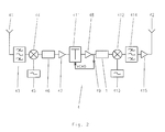
- Figure 2 shows a block diagram of a repeater (or Gap-Filler) 4 with a flat spectrum signal processing system 1 according to the invention.
- the signal from the antenna 41 is introduced in the channel filter 43 which rejects the input signal frequency image.
- the filtered signal is introduced in a mixer 44 where it is mixed with the signal generated by a local oscillator 45.
- An intermediate frequency signal is produced at the mixer output 44.
- This signal is introduced in a surface wave filter 46, which eliminates all the undesired mixing produced in the mixer 44.
- the intermediate frequency signal is amplified by the IF amplifiers 47 and 48 and detected at the output of the latter by the detector 49.
- the signal detected is used to generate the automatic gain control voltage V AGC, which acts on the attenuator 411 so that the signal input level of the flat spectrum signal processing system 1 has a constant level for all values of input signal within the dynamic range of the repeater equipment 4.
- the output signal of the flat spectrum signal processing system is introduced in a mixer 412, where it is mixed with the local oscillator signal 413, so that the signal at the frequency of the channel which one wants to transmit, is produced at the mixer output 412.
- the mixer 412 output signal is made to pass through the channel filter 414 responsible for eliminating all undesired mixing, so that only the signal at the frequency one wants to transmit appears at its output.
- the resulting signal is made to pass through the output amplifier 415, responsible for raising the signal level until the correct value to be transmitted by the transmitting antenna 42.
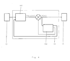
- Figure 3 shows a diagram of the flat spectrum signal processing system 1 according to the invention which, as can be observed, is formed from first a filter 11 which selects the input signal frequency band, a first frequency converter 12 which changes the signal frequency (e.g. 36 MHz) to another frequency called intermediate processing frequency (e.g. example 11 MHz), a digital/ analog converter 13 of, for example, 9 bits which converts the analog signal to digital by a sampling rate of, for example, 45.66 million samples per second; the digital samples are processed in a second filter 14, which is digital and 240-coefficient adaptive of which, only one of each three (a3, a6,....a240; 80 in total) are other than zero, an additional coefficient b adjusts the output level.
- a filter 11 which selects the input signal frequency band
- a first frequency converter 12 which changes the signal frequency (e.g. 36 MHz) to another frequency called intermediate processing frequency (e.g. example 11 MHz)
- a digital/ analog converter 13 of, for example, 9 bits which converts the analog signal to
- the output of the second adaptive digital filter 14 is reconverted in analog in a digital/ analog converter 15, also 9-bit, receiving samples at a rate of 45.66 million samples per second. Finally, a second frequency converter 16 returns the signal to its original frequency (e.g. 36 Mhz).
- the transfer function of the second adaptive digital filter 14 of the flat spectrum signal processing system 1, according to the invention, will have the form. which represents the ratio between the second filter 14 output (output (n)) and the second filter 14 input (input (n)) by means of the difference equation.
- Coefficient b will serve to adjust the gain of the flat spectrum signal processing system 1 and keep its output signal power equal to its input signal power.
- the other coefficients, a1 etc,an will serve to eliminate the distortions present in the signal as a consequence of the coupling which will inevitably occur between the receiving antenna 41 and the transmitting antenna 42 of the repeater 4 as well as the distortions produced in the multipath channel 3 and 5 and the distortions produced by the repeater (or Gap-Filler ) 4.
- the signal has a flat spectrum (e.g. COFDM signals) minimizing the power output of the flat spectrum signal processing system 1 is equivalent to flattening the spectrum of said signal, i.e. to eliminate the effects of the multipath 3 and 5 and the repeater 4 coupling.
- the number of N coefficients of the transfer function denominator of the second adaptive digital filter 14 should be sufficient to compensate the multipath channel 3 multipath and the repeater 4 coupling.
- the multipath delay is the maximum time difference between the different paths the signal follows from the transmitter 2 until the repeater 4 input.
- the repeater 4 delay is that caused by the filters 43 and 413 thereof, as regards which, the time that the output signal takes to couple back to the receiving antenna 41 can be rejected.
- Value N multiplied by the sampling period at which the second adaptive digital filter 14 operates should be greater than any of said delays.
- the optimum solution for the second filter 14 is its implementation using an unstable filter. So, in the ideal case wherein there is no multipath, if the repeater 4 gain margin is lower than zero, the second optimum filter 14 is unstable.
- a gain margin expressed in negative decibels indicates that the link formed by the repeater 4, with coupling, acts as an amplifier, which means more power returns to the receiving antenna 41 than enters in the repeater 4.
- the coefficient adaptation of the second filter 14 can be represented in a non-limiting manner in the following way.
- a k (n+1) a k (n)+ ⁇ *s(n)* s(n-k) , 1 ⁇ k ⁇ N
- the N feedback coefficients are adapted through the Pseudolinear Regression Approach algorithm.
- the signal s(n) is the output of the second filter 14, whose power should be minimized so that the spectrum is as flat as possible.
- the adaptation concept ⁇ is a value which affects the speed of convergence and final residual error as regards the optimal solution; its value should be appropriately chosen.
- This ratio guarantees that the power input and output of the flat spectrum signal processing system 1 are equalized once this has converged to its optimal value.
- the proposed system functions with the digitized version of the signal which has a flat spectrum (e.g.: COFDM signal), which conditions the sampling rates at which it can be used in converters 12 and 13.
- COFDM signal e.g.: COFDM signal
- a structure is used wherein the coefficient adaptation of the second filter 14 is performed at a rate meaning the digital signal occupies the entire frequency range ( - ⁇ , ⁇ ), whilst the filtering operation of the second filter 14 is performed at a higher speed so that part of the digital signal spectrum is content-free.
- the signal is complex i.e. it is necessary to use two digital/ analog converters.
- any frequency of form fs 2B.M, with M being a whole number greater than or equal to one, avoids the overlapping of the samples with which said frequency is valid.
- the most appropriate are those wherein the resulting digital spectrum is separated from frequencies 0 and ⁇ to, in this way, facilitate the filtering operations of converters 13 and 15 and avoid necessarily good analog or digital filters.
- oversampling can also be applied to the baseband signal.
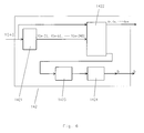
- Figure 4 shows a block diagram where we can observe the elements that comprise the second adaptive digital filter 14: a digital filtering element 141 and a coefficient adaptation element 142.
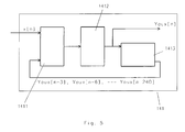
- the digital filtering element 141 is comprised of a multiplication stage 1411, an addition and accumulation stage 1412 and a delay stage 1413.
- the filtering consists of subtracting the sum of each multiplication between the coefficients and the auxiliary output feedback sample from the input value x[n]: a3*yaux[n-3] + a6*yaux[n-6] + ... + a240*yaux[n-240].
- each delayed auxiliary output sample (yaux[n-3], yaux[n-6],..., yaux[n-240]) is multiplied by the corresponding coefficient (a3, a6,..., a240).
- These operations are performed by using hardware multipliers which take two 9-bit numbers, interpreted as whole numbers with signum in two's complement and generate the 18-bit result, also as a whole number with signum represented in the format of two's complement.
- each multiplier makes three products for each input sample.
- Multiplexes select one from the three pairs of operands for each multiplier. This fact, together with the use of chained or pipeline records, achieves the spatial and time overlapping of the operations. Thus, 80 multiplications are performed using only 27 multipliers functioning at three times the speed of the input sample rate. Additionally, the input value sign (x[n]) is also changed, multiplying it by -1, whose representation varies, depending on the mode, according to the position of the decimal point used.
- the results of the multiplications of the previous stage are added, including the input value x[n] with sign change.
- the use of pipeline records and the accumulator set to zero permit the total value of the sum to be obtained, bearing in mind the fact that each multiplier has performed 3 operations for each input sample.
- the previous operations are performed with no precision loss, which means the result is a number represented with 25 bits.
- a multiplex selects the appropriate bits according to the position of the decimal point and makes the pitch to 9-bit with rounding off.
- the result sign changes in order to produce the desired value of x[n] minus the sum of the products which form the auxiliary output yaux[n]. of the digital filtering element 141.
- the delay stage 1413 of the digital filtering element 141 auxiliary output consists of a record chain, where each record transfers its content to the next one. A simultaneous transfer is made in all the records for each input sample to the filter.
- the output of one of each three records is accessible producing, from the auxiliary output yaux[n], the delayed auxiliary outputs, multiples of three samples (yaux[n-3], yaux[n-6],..., yaux[n-240]).
- the coefficient adaptation element 142 consists of a delay stage 1421, adaptation blocks 1422, an addition stage 1423 and a square root stage 1424.
- the coefficient adaptation consists of the calculation of a new array of coefficients a3, a6,..., a240 and b for the filtering, from the current values of said coefficients and the current output samples y[n] and delayed output samples y[n-3], y[n-6],..., y[n-240].
- the new value of b is calculated as the square root of 1 plus the addition of the new ai coefficients to the square.
- the delay stage 1421 consists of a chain of records, where each record transfers its contents to the next for each filter input sample.
- the output of one of each three records is stored in an additional record which is updated just once for each three filter input samples.
- the delayed output values are produced [n-3], y[n-6],...,y[n-240], from the filter output value y[n], but are updated at a rate three times less that the sampling rate.
- Each one of the 20 adaptation blocks 1422 calculates 4 a coefficients and produces a sum to the square to calculate coefficient b.
- the nucleus of each block is formed from a multiplier. This multiplier is used 8 times for each new array of 4 a coefficients.
- a multiplex selects the input value y[n] and the value y[n-i] corresponding to the coefficient to be updated. From the result, another multiplex selects the bits appropriate for the position of the decimal point and the pitch of the current model.
- An adder adds the current value of the coefficient, represented with 18 bits, to the new increase and stores it in an 18-bit record. The new value of the coefficient overwrites the previous value.
- a mechanism has been provided which prevents the overflowing of the record of each coefficient: if the new result after the addition was too large, that coefficient would not be updated, which would reduce the appearance of instabilities and transients with adverse input sequences.
- the multiplier input multiplexes select that new value obtaining its value to the square.
- Accumulation records calculate the sum of the four new coefficients to the square.
- the values to the square of the new a coefficients plus the value one are added, represented corresponding to the position of the decimal point.
- pipeline records are not necessary as this operation is only necessary once out of every three 3 input samples and the schema adopted is sufficiently fast to perform the whole operation in a single cycle, without needing to divide it in several cycles.
- the square root stage 1424 takes the appropriate 16 bits from the previous stage, from the 25 bits resulting from the sum without losing precision, and calculates the square root, producing 8 effective bits.
- the ninth bit, the sign bit always has the same value and is not calculated as the positive result of the root is taken, forming the new value of b.
- the root is calculated in combination form, in a single cycle, and links to the addition stage without requiring pipeline records, as both operations can be performed in the time between three filter input samples.
Landscapes
- Engineering & Computer Science (AREA)
- Computer Networks & Wireless Communication (AREA)
- Signal Processing (AREA)
- Power Engineering (AREA)
- Cable Transmission Systems, Equalization Of Radio And Reduction Of Echo (AREA)
- Radio Relay Systems (AREA)
- Analogue/Digital Conversion (AREA)
Applications Claiming Priority (2)
| Application Number | Priority Date | Filing Date | Title |
|---|---|---|---|
| ES200400002A ES2274659B2 (es) | 2003-12-23 | 2003-12-23 | Sistema de procesado de señales de espectro plano. |
| ES200400002 | 2003-12-23 |
Publications (3)
| Publication Number | Publication Date |
|---|---|
| EP1555769A2 true EP1555769A2 (de) | 2005-07-20 |
| EP1555769A3 EP1555769A3 (de) | 2012-11-21 |
| EP1555769B1 EP1555769B1 (de) | 2017-02-22 |
Family
ID=34610366
Family Applications (1)
| Application Number | Title | Priority Date | Filing Date |
|---|---|---|---|
| EP04030613.6A Expired - Lifetime EP1555769B1 (de) | 2003-12-23 | 2004-12-23 | Signalverarbeitungssystem für ein flaches Spektrum |
Country Status (2)
| Country | Link |
|---|---|
| EP (1) | EP1555769B1 (de) |
| ES (2) | ES2274659B2 (de) |
Cited By (3)
| Publication number | Priority date | Publication date | Assignee | Title |
|---|---|---|---|---|
| EP1748578A1 (de) * | 2005-07-25 | 2007-01-31 | Harris Broadcast Systems Europe | Verfahren und Gerät zur Zwischenverstärkung von Gleichfrequenzsignalen |
| EP2053812A2 (de) | 2007-10-22 | 2009-04-29 | British Broadcasting Corporation | Selbsteinstellender Filter für ein On-Kanal-Relais oder zur Beseitigung von Übersprechen zwischen Quadraturkanälen |
| EP1744455A3 (de) * | 2005-07-12 | 2012-11-28 | Tredess 2010, S.L. | Signalverarbeitungssystem zur Spektrumformung |
Citations (5)
| Publication number | Priority date | Publication date | Assignee | Title |
|---|---|---|---|---|
| ES216008A1 (es) | 1954-06-18 | 1955-11-16 | Ludwing Schlebusch M | Dispositivo de cribado, calentado o influenciado inductivamente |
| EP0772310A2 (de) | 1995-10-30 | 1997-05-07 | British Broadcasting Corporation | Funksender für Wiederübertragung von OFDM-Signalen |
| JP2000031877A (ja) | 1998-07-09 | 2000-01-28 | Sharp Corp | 移動通信方式 |
| JP2002330112A (ja) | 2001-04-27 | 2002-11-15 | Nippon Hoso Kyokai <Nhk> | Ofdmデジタル信号中継装置 |
| DE10155179A1 (de) | 2001-11-12 | 2003-05-22 | Mikom Gmbh | Digitaler Repeater mit Bandpassfilterung, adaptiver Vorentzerrung und Unterdrückung der Eigenschwingung |
Family Cites Families (2)
| Publication number | Priority date | Publication date | Assignee | Title |
|---|---|---|---|---|
| JP4409639B2 (ja) * | 1998-06-10 | 2010-02-03 | 日本放送協会 | 回り込みキャンセラ |
| ITTO20020076A1 (it) * | 2002-01-28 | 2003-07-28 | Rai Radiotelevisione Italiana | Procedimento e apparato di cancellazione del segnale di rientro in unripetitore di tipo gap filler per reti a singola frequenza dvb-t. |
-
2003
- 2003-12-23 ES ES200400002A patent/ES2274659B2/es not_active Expired - Lifetime
-
2004
- 2004-12-23 ES ES04030613.6T patent/ES2621311T3/es not_active Expired - Lifetime
- 2004-12-23 EP EP04030613.6A patent/EP1555769B1/de not_active Expired - Lifetime
Patent Citations (5)
| Publication number | Priority date | Publication date | Assignee | Title |
|---|---|---|---|---|
| ES216008A1 (es) | 1954-06-18 | 1955-11-16 | Ludwing Schlebusch M | Dispositivo de cribado, calentado o influenciado inductivamente |
| EP0772310A2 (de) | 1995-10-30 | 1997-05-07 | British Broadcasting Corporation | Funksender für Wiederübertragung von OFDM-Signalen |
| JP2000031877A (ja) | 1998-07-09 | 2000-01-28 | Sharp Corp | 移動通信方式 |
| JP2002330112A (ja) | 2001-04-27 | 2002-11-15 | Nippon Hoso Kyokai <Nhk> | Ofdmデジタル信号中継装置 |
| DE10155179A1 (de) | 2001-11-12 | 2003-05-22 | Mikom Gmbh | Digitaler Repeater mit Bandpassfilterung, adaptiver Vorentzerrung und Unterdrückung der Eigenschwingung |
Cited By (3)
| Publication number | Priority date | Publication date | Assignee | Title |
|---|---|---|---|---|
| EP1744455A3 (de) * | 2005-07-12 | 2012-11-28 | Tredess 2010, S.L. | Signalverarbeitungssystem zur Spektrumformung |
| EP1748578A1 (de) * | 2005-07-25 | 2007-01-31 | Harris Broadcast Systems Europe | Verfahren und Gerät zur Zwischenverstärkung von Gleichfrequenzsignalen |
| EP2053812A2 (de) | 2007-10-22 | 2009-04-29 | British Broadcasting Corporation | Selbsteinstellender Filter für ein On-Kanal-Relais oder zur Beseitigung von Übersprechen zwischen Quadraturkanälen |
Also Published As
| Publication number | Publication date |
|---|---|
| ES2274659A1 (es) | 2007-05-16 |
| EP1555769B1 (de) | 2017-02-22 |
| ES2621311T3 (es) | 2017-07-03 |
| ES2274659B2 (es) | 2008-08-01 |
| EP1555769A3 (de) | 2012-11-21 |
Similar Documents
| Publication | Publication Date | Title |
|---|---|---|
| CN101232298B (zh) | 一种接收机及接收无线信号的方法 | |
| US8023587B2 (en) | Device and method for pre-distorting a base-band digital signal | |
| US8140106B2 (en) | Peak factor reduction device and base station | |
| AU639225B2 (en) | Adaptive predistortion circuit | |
| US8805298B2 (en) | Transceiver with compensation for transmit signal leakage and method therefor | |
| US7142616B2 (en) | Front end processor for data receiver and nonlinear distortion equalization method | |
| EP1386463B1 (de) | Schwundkontrol für satellitenaufwärtsrichtung | |
| US7358798B1 (en) | Nonlinear filter | |
| EP0588444B1 (de) | Modulationsanordnung, die Nichtlinearitäten eines dazugehörigen Verstärkers genau zu kompensieren vermag | |
| EP0864206B1 (de) | Verfahren und nichtlineares filter zur verminderung der gleichkanalstörung | |
| US20040076247A1 (en) | Peak-to-average power ratio modifier | |
| US4775988A (en) | Method for rapid gain acquisition in a modem receiver | |
| US7561629B2 (en) | Multicarrier receiver and transmitter with delay correcting function | |
| JPH03135232A (ja) | デジタル送信システム用先行歪ませ装置 | |
| US6360369B1 (en) | Interference tolerant modem | |
| US7026873B2 (en) | LMS-based adaptive pre-distortion for enhanced power amplifier efficiency | |
| US20020158990A1 (en) | Frequency converter | |
| US8948303B1 (en) | Communication device and method of crest factor reduction using amplitude compression | |
| JPS6349928B2 (de) | ||
| US20030157905A1 (en) | Transmitter and associated method for reducing the adjacent channel power during wireless communications | |
| US6741644B1 (en) | Pre-emphasis filter and method for ISI cancellation in low-pass channel applications | |
| EP1555769A2 (de) | Signalverarbeitungssystem für ein flaches Spektrum | |
| EP1912348B1 (de) | Relais-sendervorrichtung | |
| EP1280272B1 (de) | Verfahren zur Linearisierung der Leistungsstufe eines Senders und entsprechendes System | |
| US5530721A (en) | Equalizer and terminal device for mobile communications |
Legal Events
| Date | Code | Title | Description |
|---|---|---|---|
| PUAI | Public reference made under article 153(3) epc to a published international application that has entered the european phase |
Free format text: ORIGINAL CODE: 0009012 |
|
| AK | Designated contracting states |
Kind code of ref document: A2 Designated state(s): AT BE BG CH CY CZ DE DK EE ES FI FR GB GR HU IE IS IT LI LT LU MC NL PL PT RO SE SI SK TR |
|
| AX | Request for extension of the european patent |
Extension state: AL BA HR LV MK YU |
|
| PUAL | Search report despatched |
Free format text: ORIGINAL CODE: 0009013 |
|
| AK | Designated contracting states |
Kind code of ref document: A3 Designated state(s): AT BE BG CH CY CZ DE DK EE ES FI FR GB GR HU IE IS IT LI LT LU MC NL PL PT RO SE SI SK TR |
|
| AX | Request for extension of the european patent |
Extension state: AL BA HR LV MK YU |
|
| RIC1 | Information provided on ipc code assigned before grant |
Ipc: H04L 27/26 20060101ALI20121019BHEP Ipc: H04L 25/03 20060101ALI20121019BHEP Ipc: H04B 7/155 20060101AFI20121019BHEP |
|
| 17P | Request for examination filed |
Effective date: 20130521 |
|
| AKX | Designation fees paid |
Designated state(s): AT BE BG CH CY CZ DE DK EE ES FI FR GB GR HU IE IS IT LI LT LU MC NL PL PT RO SE SI SK TR |
|
| 17Q | First examination report despatched |
Effective date: 20130710 |
|
| GRAJ | Information related to disapproval of communication of intention to grant by the applicant or resumption of examination proceedings by the epo deleted |
Free format text: ORIGINAL CODE: EPIDOSDIGR1 |
|
| GRAP | Despatch of communication of intention to grant a patent |
Free format text: ORIGINAL CODE: EPIDOSNIGR1 |
|
| INTG | Intention to grant announced |
Effective date: 20161109 |
|
| RIN1 | Information on inventor provided before grant (corrected) |
Inventor name: LOPEZ VALCARCE, ROBERTO Inventor name: MOSQUERA NARTALLO, CARLOS Inventor name: PIETO DAVILA, ALBERTO Inventor name: PEREZ GONZALES, FERNANDO |
|
| GRAS | Grant fee paid |
Free format text: ORIGINAL CODE: EPIDOSNIGR3 |
|
| GRAA | (expected) grant |
Free format text: ORIGINAL CODE: 0009210 |
|
| AK | Designated contracting states |
Kind code of ref document: B1 Designated state(s): AT BE BG CH CY CZ DE DK EE ES FI FR GB GR HU IE IS IT LI LT LU MC NL PL PT RO SE SI SK TR |
|
| REG | Reference to a national code |
Ref country code: GB Ref legal event code: FG4D |
|
| REG | Reference to a national code |
Ref country code: CH Ref legal event code: EP |
|
| REG | Reference to a national code |
Ref country code: AT Ref legal event code: REF Ref document number: 870005 Country of ref document: AT Kind code of ref document: T Effective date: 20170315 |
|
| REG | Reference to a national code |
Ref country code: IE Ref legal event code: FG4D |
|
| REG | Reference to a national code |
Ref country code: DE Ref legal event code: R096 Ref document number: 602004050791 Country of ref document: DE |
|
| REG | Reference to a national code |
Ref country code: LT Ref legal event code: MG4D |
|
| REG | Reference to a national code |
Ref country code: NL Ref legal event code: MP Effective date: 20170222 |
|
| REG | Reference to a national code |
Ref country code: ES Ref legal event code: FG2A Ref document number: 2621311 Country of ref document: ES Kind code of ref document: T3 Effective date: 20170703 |
|
| REG | Reference to a national code |
Ref country code: AT Ref legal event code: MK05 Ref document number: 870005 Country of ref document: AT Kind code of ref document: T Effective date: 20170222 |
|
| PG25 | Lapsed in a contracting state [announced via postgrant information from national office to epo] |
Ref country code: GR Free format text: LAPSE BECAUSE OF FAILURE TO SUBMIT A TRANSLATION OF THE DESCRIPTION OR TO PAY THE FEE WITHIN THE PRESCRIBED TIME-LIMIT Effective date: 20170523 Ref country code: LT Free format text: LAPSE BECAUSE OF FAILURE TO SUBMIT A TRANSLATION OF THE DESCRIPTION OR TO PAY THE FEE WITHIN THE PRESCRIBED TIME-LIMIT Effective date: 20170222 Ref country code: FI Free format text: LAPSE BECAUSE OF FAILURE TO SUBMIT A TRANSLATION OF THE DESCRIPTION OR TO PAY THE FEE WITHIN THE PRESCRIBED TIME-LIMIT Effective date: 20170222 |
|
| PG25 | Lapsed in a contracting state [announced via postgrant information from national office to epo] |
Ref country code: AT Free format text: LAPSE BECAUSE OF FAILURE TO SUBMIT A TRANSLATION OF THE DESCRIPTION OR TO PAY THE FEE WITHIN THE PRESCRIBED TIME-LIMIT Effective date: 20170222 Ref country code: PT Free format text: LAPSE BECAUSE OF FAILURE TO SUBMIT A TRANSLATION OF THE DESCRIPTION OR TO PAY THE FEE WITHIN THE PRESCRIBED TIME-LIMIT Effective date: 20170622 Ref country code: BG Free format text: LAPSE BECAUSE OF FAILURE TO SUBMIT A TRANSLATION OF THE DESCRIPTION OR TO PAY THE FEE WITHIN THE PRESCRIBED TIME-LIMIT Effective date: 20170522 Ref country code: SE Free format text: LAPSE BECAUSE OF FAILURE TO SUBMIT A TRANSLATION OF THE DESCRIPTION OR TO PAY THE FEE WITHIN THE PRESCRIBED TIME-LIMIT Effective date: 20170222 Ref country code: NL Free format text: LAPSE BECAUSE OF FAILURE TO SUBMIT A TRANSLATION OF THE DESCRIPTION OR TO PAY THE FEE WITHIN THE PRESCRIBED TIME-LIMIT Effective date: 20170222 |
|
| PG25 | Lapsed in a contracting state [announced via postgrant information from national office to epo] |
Ref country code: RO Free format text: LAPSE BECAUSE OF FAILURE TO SUBMIT A TRANSLATION OF THE DESCRIPTION OR TO PAY THE FEE WITHIN THE PRESCRIBED TIME-LIMIT Effective date: 20170222 Ref country code: CZ Free format text: LAPSE BECAUSE OF FAILURE TO SUBMIT A TRANSLATION OF THE DESCRIPTION OR TO PAY THE FEE WITHIN THE PRESCRIBED TIME-LIMIT Effective date: 20170222 Ref country code: IT Free format text: LAPSE BECAUSE OF FAILURE TO SUBMIT A TRANSLATION OF THE DESCRIPTION OR TO PAY THE FEE WITHIN THE PRESCRIBED TIME-LIMIT Effective date: 20170222 Ref country code: EE Free format text: LAPSE BECAUSE OF FAILURE TO SUBMIT A TRANSLATION OF THE DESCRIPTION OR TO PAY THE FEE WITHIN THE PRESCRIBED TIME-LIMIT Effective date: 20170222 Ref country code: SK Free format text: LAPSE BECAUSE OF FAILURE TO SUBMIT A TRANSLATION OF THE DESCRIPTION OR TO PAY THE FEE WITHIN THE PRESCRIBED TIME-LIMIT Effective date: 20170222 |
|
| REG | Reference to a national code |
Ref country code: DE Ref legal event code: R097 Ref document number: 602004050791 Country of ref document: DE |
|
| PG25 | Lapsed in a contracting state [announced via postgrant information from national office to epo] |
Ref country code: PL Free format text: LAPSE BECAUSE OF FAILURE TO SUBMIT A TRANSLATION OF THE DESCRIPTION OR TO PAY THE FEE WITHIN THE PRESCRIBED TIME-LIMIT Effective date: 20170222 Ref country code: DK Free format text: LAPSE BECAUSE OF FAILURE TO SUBMIT A TRANSLATION OF THE DESCRIPTION OR TO PAY THE FEE WITHIN THE PRESCRIBED TIME-LIMIT Effective date: 20170222 |
|
| REG | Reference to a national code |
Ref country code: FR Ref legal event code: PLFP Year of fee payment: 14 |
|
| PLBE | No opposition filed within time limit |
Free format text: ORIGINAL CODE: 0009261 |
|
| STAA | Information on the status of an ep patent application or granted ep patent |
Free format text: STATUS: NO OPPOSITION FILED WITHIN TIME LIMIT |
|
| 26N | No opposition filed |
Effective date: 20171123 |
|
| PG25 | Lapsed in a contracting state [announced via postgrant information from national office to epo] |
Ref country code: SI Free format text: LAPSE BECAUSE OF FAILURE TO SUBMIT A TRANSLATION OF THE DESCRIPTION OR TO PAY THE FEE WITHIN THE PRESCRIBED TIME-LIMIT Effective date: 20170222 |
|
| REG | Reference to a national code |
Ref country code: CH Ref legal event code: PL |
|
| GBPC | Gb: european patent ceased through non-payment of renewal fee |
Effective date: 20171223 |
|
| REG | Reference to a national code |
Ref country code: IE Ref legal event code: MM4A |
|
| PG25 | Lapsed in a contracting state [announced via postgrant information from national office to epo] |
Ref country code: LU Free format text: LAPSE BECAUSE OF NON-PAYMENT OF DUE FEES Effective date: 20171223 |
|
| REG | Reference to a national code |
Ref country code: BE Ref legal event code: MM Effective date: 20171231 |
|
| PG25 | Lapsed in a contracting state [announced via postgrant information from national office to epo] |
Ref country code: IE Free format text: LAPSE BECAUSE OF NON-PAYMENT OF DUE FEES Effective date: 20171223 |
|
| PG25 | Lapsed in a contracting state [announced via postgrant information from national office to epo] |
Ref country code: BE Free format text: LAPSE BECAUSE OF NON-PAYMENT OF DUE FEES Effective date: 20171231 Ref country code: GB Free format text: LAPSE BECAUSE OF NON-PAYMENT OF DUE FEES Effective date: 20171223 Ref country code: CH Free format text: LAPSE BECAUSE OF NON-PAYMENT OF DUE FEES Effective date: 20171231 Ref country code: LI Free format text: LAPSE BECAUSE OF NON-PAYMENT OF DUE FEES Effective date: 20171231 |
|
| PG25 | Lapsed in a contracting state [announced via postgrant information from national office to epo] |
Ref country code: MC Free format text: LAPSE BECAUSE OF FAILURE TO SUBMIT A TRANSLATION OF THE DESCRIPTION OR TO PAY THE FEE WITHIN THE PRESCRIBED TIME-LIMIT Effective date: 20170222 Ref country code: HU Free format text: LAPSE BECAUSE OF FAILURE TO SUBMIT A TRANSLATION OF THE DESCRIPTION OR TO PAY THE FEE WITHIN THE PRESCRIBED TIME-LIMIT; INVALID AB INITIO Effective date: 20041223 |
|
| REG | Reference to a national code |
Ref country code: DE Ref legal event code: R082 Ref document number: 602004050791 Country of ref document: DE |
|
| PG25 | Lapsed in a contracting state [announced via postgrant information from national office to epo] |
Ref country code: CY Free format text: LAPSE BECAUSE OF NON-PAYMENT OF DUE FEES Effective date: 20170222 |
|
| PGFP | Annual fee paid to national office [announced via postgrant information from national office to epo] |
Ref country code: DE Payment date: 20191210 Year of fee payment: 16 |
|
| PG25 | Lapsed in a contracting state [announced via postgrant information from national office to epo] |
Ref country code: TR Free format text: LAPSE BECAUSE OF FAILURE TO SUBMIT A TRANSLATION OF THE DESCRIPTION OR TO PAY THE FEE WITHIN THE PRESCRIBED TIME-LIMIT Effective date: 20170222 |
|
| PG25 | Lapsed in a contracting state [announced via postgrant information from national office to epo] |
Ref country code: IS Free format text: LAPSE BECAUSE OF FAILURE TO SUBMIT A TRANSLATION OF THE DESCRIPTION OR TO PAY THE FEE WITHIN THE PRESCRIBED TIME-LIMIT Effective date: 20170622 |
|
| PGFP | Annual fee paid to national office [announced via postgrant information from national office to epo] |
Ref country code: FR Payment date: 20201210 Year of fee payment: 17 |
|
| REG | Reference to a national code |
Ref country code: DE Ref legal event code: R119 Ref document number: 602004050791 Country of ref document: DE |
|
| PG25 | Lapsed in a contracting state [announced via postgrant information from national office to epo] |
Ref country code: DE Free format text: LAPSE BECAUSE OF NON-PAYMENT OF DUE FEES Effective date: 20210701 |
|
| PG25 | Lapsed in a contracting state [announced via postgrant information from national office to epo] |
Ref country code: FR Free format text: LAPSE BECAUSE OF NON-PAYMENT OF DUE FEES Effective date: 20211231 |
|
| PGFP | Annual fee paid to national office [announced via postgrant information from national office to epo] |
Ref country code: ES Payment date: 20230102 Year of fee payment: 19 |
|
| REG | Reference to a national code |
Ref country code: ES Ref legal event code: FD2A Effective date: 20250203 |
|
| PG25 | Lapsed in a contracting state [announced via postgrant information from national office to epo] |
Ref country code: ES Free format text: LAPSE BECAUSE OF NON-PAYMENT OF DUE FEES Effective date: 20231224 |