US7358798B1 - Nonlinear filter - Google Patents
Nonlinear filter Download PDFInfo
- Publication number
- US7358798B1 US7358798B1 US11/036,662 US3666205A US7358798B1 US 7358798 B1 US7358798 B1 US 7358798B1 US 3666205 A US3666205 A US 3666205A US 7358798 B1 US7358798 B1 US 7358798B1
- Authority
- US
- United States
- Prior art keywords
- nonlinear
- adc
- filter
- adaptive filter
- output
- Prior art date
- Legal status (The legal status is an assumption and is not a legal conclusion. Google has not performed a legal analysis and makes no representation as to the accuracy of the status listed.)
- Expired - Lifetime
Links
Images


Classifications
-
- H—ELECTRICITY
- H03—ELECTRONIC CIRCUITRY
- H03H—IMPEDANCE NETWORKS, e.g. RESONANT CIRCUITS; RESONATORS
- H03H17/00—Networks using digital techniques
- H03H17/02—Frequency selective networks
- H03H17/0248—Filters characterised by a particular frequency response or filtering method
- H03H17/0261—Non linear filters
Definitions
- the present invention relates generally to nonlinear filters. More specifically, a nonlinear filter synthesized from a combination of linear filters and nonlinear elements is disclosed.
- DSP Digital signal processing
- ADC analog to digital converter
- every portion of the signal path including the signal source, the receiver's analog front-end, the ADC, should be linear, thus allowing traditional linear signal processing techniques to be used to correct for any linear distortion that corrupts the received signal.
- most systems are nonlinear. There are many sources that introduce nonlinearity to the signal path, including the transmitter/receiver electronics and the channel medium.
- a major source of the nonlinearity is the ADC. Component mismatches, quantization errors, and limited bandwidth of amplifiers are some of the factors contributing to the nonlinearities.
- FIG. 1A is a block diagram illustrating the modeling of a channel.
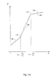
- FIG. 1B is a chart illustrating one approach to the modeling of a nonlinear function according to present invention.
- FIGS. 2A-2B are block diagrams illustrating a linear filter based nonlinear filter implementation according to one embodiment of the present invention.
- FIGS. 3A-3C are charts illustrating the min-max method used for approximating a higher order nonlinear function, according to one embodiment of the present invention.
- FIGS. 4A-4B are block diagrams illustrating a nonlinear filter embodiment using the min-max algorithm, according to one embodiment of the present invention.
- FIG. 5 is a block diagram illustrating a nonlinear filter embodiment that is configured for training.
- FIG. 6 is a graph illustrating transfer functions of two analog to digital converters (ADC's).
- FIG. 8 is a diagram illustrating how a minimum function is applied in a three dimensional system.
- the transfer function of the nonlinear filter is an approximation of an original, nonlinear transfer function.
- the nonlinear filter includes a plurality of linear filters connected to nonlinear elements to produce nonlinear outputs.
- a combination network combines the nonlinear outputs to achieve the desired nonlinear transfer function.
- the nonlinear elements are absolute value operators.
- the combination network includes a summation network.
- the combination network includes a min-max selection network.
- the filter can be adaptively trained to model nonlinear systems, and is particularly useful in one embodiment used in an ADC for error reduction.
- FIG. 1A is a block diagram illustrating the modeling of a channel.
- An input, X is sent to a channel represented by block 150 , and a filter 152 that models the characteristics of the channel.
- Y and Z are the outputs of the channel and the filter, respectively. If the transfer characteristics of the filter are sufficiently close to the transfer characteristics of the channel, then Y and Z are approximately the same.
- Channel modeling is useful for a variety of purposes, such as distortion cancellation and equalizer design. While it is relatively straightforward to model linear channels, it is often much more difficult to model nonlinear channels since the channel characteristics are often expressed as higher order nonlinear polynomials.
- the present invention approximates the nonlinear functions with functions that are first order polynomials.
- the approximation is used to design filters comprised of linear filters.
- the parameters of the linear filters are derived from the linear functions.
- FIG. 1B is a chart illustrating one approach to the approximation of a nonlinear function according to present invention.
- a nonlinear function 100 (shown as a dashed line) is approximated by linear segments 102 , 104 , and 106 .
- the linear segments are derived using techniques such as least mean square fit.
- This function can be implemented using linear filters and nonlinear elements.
- the parameters of the linear filters are determined by the parameters in the function. It should be noted that the approximation function remains nonlinear due to the absolute value operations.
- Break points 110 , and 112 are locations where the slopes of the segments change, and they correspond to x values of ⁇ 1 / ⁇ 1 and ⁇ 2 / ⁇ 2 , respectively.
- the difference between the slope of segments 102 and the slope of 104 is 2c 1 ⁇ 1 ; and the slope difference between segments 104 and 106 is 2c 2 ⁇ 2 .
- the approximation method can be generalized to model nonlinear functions. Since the resulting approximation function is comprised of linear segments that are first order polynomials, it is less complex than the original nonlinear function that is comprised of higher order polynomials, and the corresponding filter implementation is more straightforward. It is now possible to use linear filters to implement a nonlinear filter whose transfer function approximates the original, more complex nonlinear transfer function.
- the first order polynomials in the linearized function are easier to compute and manipulate than the higher order polynomials in the original nonlinear function.
- the simplified approximation function makes it possible to adjust the filter design to make tradeoffs yet still keep the system stable. For example, the zeroes of a linearized function may be shifted to achieve better response time, and the poles may be adjusted to stay within the desired regions to ensure system stability. It would be more difficult to make such adjustments to a higher order nonlinear system since the poles and zeros of higher order polynomials tend to be less well behaved.
- FIGS. 2A-2B are block diagrams illustrating a linear filter based nonlinear filter implementation according to one embodiment of the present invention.
- FIG. 2A illustrates the overall architecture of the nonlinear filter.
- the input vector X is sent to linear filters 200 , 202 , and 204 .
- the outputs of filters 202 and 204 are sent to nonlinear elements 208 and 210 , respectively.
- a nonlinear element may be a discrete component, a part of an integrated circuit chip, a processor, or any other appropriate hardware and/or software for providing a nonlinear transformation to an input.
- each of the nonlinear elements is an absolute value operator that applies an absolute value function to its input.
- the outputs of the nonlinear elements and the output of filter 200 are combined by a combination network 230 to produce the desired transfer function.
- the combination network is a summation network comprised of multipliers 214 and 216 , and combiner 228 .
- the outputs of nonlinear elements 208 and 210 are scaled by factors of C 1 and C 2 , via multipliers 214 and 216 , respectively.
- the scaled nonlinear outputs and the output from filter 200 are summed by combiner 228 to produce an output having a transfer function similar to Equation 1.
- FIG. 2B illustrates the details of linear filter 200 shown in FIG. 2A .
- the input is scaled by a factor a 0 using a multiplier 250 .
- the input is also sent to a plurality of delay stages 252 , 254 , 256 and 258 .
- the delayed signals are scaled by factors of a 1 , a 2 , a 3 and a 4 .
- the scaled signals are combined by a combiner 262 .
- a constant value b 0 is added to the combined result via another combiner 260 to generate the output.
- the output of filter 200 provides an averaging effect to the overall nonlinear filter (similar to the term a ⁇ x+b 0 in equation 1,) thus filter 200 is sometimes referred to as an averaging filter.
- the constant value is added to the scaled signals directly by combiner 262 , thus combiner 260 is omitted.
- Different types of linear filters may be employed in other embodiments.
- the linear filters 202 and 204 shown in FIG. 2A have similar architecture as the one shown in FIG. 2B , although the number of delays and the scaling factors vary for different filters. These linear filters provide other terms in the transfer function, and their absolute values are taken and combined to produce the desired output. In other embodiments, the linear filters may have different designs than what is shown in FIG. 2B .
- FIGS. 3A-3C are charts illustrating the min-max method used for approximating a higher order nonlinear function, according to one embodiment of the present invention.
- a nonlinear function 300 (shown as a dashed line) is approximated by linear segments 302 , 304 and 306 . These line segments are obtained using a min-max process shown in FIGS. 3B and 3C .
- FIG. 3B illustrates a minimum function applied to two lines 308 and 310 .
- Line 308 referred to as L 1
- Line 310 referred to as L 2
- L 1 is a line on which segment 302 lies.
- Line 310 referred to as L 2
- L 2 is a line that includes segment 304 .
- min L 1 , L 2
- the selected parts of the lines are shown in solid, and the discarded parts are shown in dash.
- FIG. 3C illustrates a maximum functions applied to line 312 and min (L 1 , L 2 ).
- Line 312 referred to as L 3
- L 3 is a line that includes segment 306 .
- a maximum function expressed as max (L 3 , min (L 1 , L 2 )), is applied to L 3 and the result of the minimum function shown in FIG. 3B .
- the maximum values are selected.
- the selected portions are shown in solid whereas the discarded portions are shown in dash.
- segments 302 , 304 and 306 are selected.
- Equations 2 and 3 represent the transfer functions of two linear filters, a 1 ⁇ x+b 1 and a 2 ⁇ x+b 2 , respectively. Equations 2 and 3, although comprised of linear parts, are nonlinear due to the absolute value operations. These mathematical expressions are useful for designing filters based on the min-max selection algorithm.
- Equation 4 is equivalent to Equation 1, and is expressed as a min-max combination of the linear segments and nested absolute values. This alternative form is useful in constructing, manipulating and solve nonlinear filter problems.
- FIGS. 4A-4B are block diagrams illustrating a nonlinear filter embodiment using the min-max algorithm, according to one embodiment of the present invention.
- FIG. 4A illustrates the overall architecture of the nonlinear filter.
- the input is sent to linear filters 400 , 402 and 404 , which have transfer functions characterized by lines L 1 , L 2 and L 3 , respectively.
- the filters may be implemented using the architecture shown in FIG. 2B or any other appropriate architecture.
- the filter outputs are sent to a combination network 410 .
- the combination network comprises a min-max selection network used to perform min-max selection operations on the filter outputs.
- the min-max selection network includes a minimum processor 406 and a maximum processor 408 in a nested configuration, where the output of processor 406 is sent as an input to processor 408 .
- the minimum processor selects the minimum between L 1 and L 2 , producing an output similar to what was shown in FIG. 3B .
- the maximum processor selects the maximum between L 3 and the output from the minimum processor, producing an output similar to what was shown in FIG. 3C .
- the min-max selection network is expanded to include more minimum/maximum processors.
- FIG. 4B is a schematic diagram illustrating the details of the nonlinear filter shown in FIG. 4A .
- Block 450 is the minimum processor and block 470 is the maximum processor.
- the output of linear filters 400 and the output of linear filter 402 are added by a combiner 452 , to obtain a signal with a transfer function of L 1 +L 2 .
- the output of filter 402 is also subtracted from the output of filter 400 by combiner 454 to obtain an output with a transfer function that is the difference of the two filter's transfer functions, L 1 ⁇ L 2 .
- the difference output is then sent to an absolute value processor 456 to obtain
- Multiplier 460 multiplies
- the resulting transfer function is L 1 +L 2 ⁇
- this transfer function is referred to as R from here on.
- the minimum processor output is scaled by 12 .
- the scaled minimum processor output and the output of linear filter 404 are added by a combiner 472 , to obtain a signal with a transfer function that is R+L 3 .
- the output of filter 404 is subtracted from the output of the minimum processor by combiner 474 to obtain an output with a transfer function that is the difference, R ⁇ L 3 .
- the difference is then input to an absolute value processor 476 to obtain
- Multiplier 480 multiplies
- Combiner 482 combines the multiplier's output with R+L 3 to obtain R+L 3 +
- the output of the maximum processor is then scaled by 1 ⁇ 2.
- the nonlinear filter is sometimes trained to model a system. During the training process, the parameters and configurations of the linear filters included in the nonlinear filter are determined adaptively for the filter to achieve the desired transfer characteristics.
- FIG. 5 is a block diagram illustrating a nonlinear filter embodiment that is configured for training.
- the training input is sent to both system 500 and a nonlinear filter 502 used to model the system.
- the difference between the system output and the nonlinear filter output is determined by combiner 504 .
- the difference is propagated back to the nonlinear filter.
- the nonlinear filter Based on the difference and the input, the nonlinear filter adapts the parameters and configurations of its linear filters accordingly to minimize the difference.
- Any appropriate adaptation method such as the least mean square (LMS) method
- LMS least mean square
- system 500 is an error producing subsystem that introduces errors to the overall system.
- the filter is designed to model the error producing subsystem and replicate the errors. Thus, the errors can be subtracted from the overall system output and improve the overall system linearity.
- an adaptive filter is used in conjunction with an ADC to improve its linearity.
- FIG. 6 is a graph illustrating transfer functions of two ADC's.
- a straight line 600 represents the transfer function for an ideal ADC that is perfectly linear.
- a wavy line 602 represents the transfer function for an actual ADC, which is nonlinear. There are many causes for the nonlinearity shown in line 602 , including quantization errors, component mismatches, and bandwidth limitations of devices. It would be useful to minimize the errors and improve linearity.
- FIGS. 7A-7B are block diagrams illustrating an adaptive ADC system embodiment according to the present invention.
- the system includes an adaptive filter that is trained to model the way the ADC produces the error.
- the adaptive filter is used to produce an error signal that is substantially the same as the error produced by ADC. The error is then subtracted from the output of the ADC to reduce the overall error.
- FIG. 7A illustrates the adaptive ADC system configuration during the training phase.
- a known training input, x is sent to ADC 700 .
- the output of the ADC is expressed as x + ⁇ , where ⁇ is the error of the ADC output.
- the difference between x+ ⁇ and x is computed by combiner 704 .
- x+ ⁇ is also sent to adaptive filter 702 .
- the filter dynamically adapts its parameters and configurations to produce an output that closely tracks ⁇ .
- the output of the nonlinear filter is denoted as ⁇ ′.
- the difference between ⁇ and ⁇ ′, denoted as ⁇ is computed by combiner 706 .
- the difference is propagated back to the adaptive filter.
- the filter further adapts to reduce e, until the output of the nonlinear filter is sufficiently close to the error of the ADC. At this point, the system is ready to enter steady state operation.
- FIG. 7B illustrates the steady state operation of the adaptive ADC system.
- the system is reconfigured to take advantage of the adaptive filter's ability to model the error produced by the ADC.
- the output of ADC 700 x+ ⁇ , is sent to adaptive filter 702 , which is connected to the ADC in a feedforward configuration.
- the filter has been trained to produce an output that is approximately ⁇ .
- the ADC output is also sent to combiner 710 , which subtracts the output of the adaptive filter from the output of the ADC, generating an output that is approximately x.
- the error of the ADC output is greatly reduced.
- the adaptive filter shown in FIGS. 7A-7B may be any filter that is adaptable, it is preferably a nonlinear filter comprised of linear filters.
- FIG. 8 is a diagram illustrating how a minimum function is applied in a three dimensional system.
- the system has three axes: x 1 , x 2 , and y.
- the minimum function selects the minimum of the corresponding values on P 1 and P 2 .
- the resulting function, 1 ⁇ 2 (P 1 +P 2 ⁇
- the nonlinear filter includes linear filters connected to nonlinear elements.
- a combination network is used to combine the outputs of the nonlinear elements.
- the filter is easier to implement than conventional higher order nonlinear filters. It can be adaptively trained to model nonlinear systems. It is useful in applications that need error reduction and linearity improvement, such as ADC's.
Landscapes
- Physics & Mathematics (AREA)
- Nonlinear Science (AREA)
- Engineering & Computer Science (AREA)
- Computer Hardware Design (AREA)
- Mathematical Physics (AREA)
- Filters That Use Time-Delay Elements (AREA)
- Cable Transmission Systems, Equalization Of Radio And Reduction Of Echo (AREA)
Abstract
Description
y=a·x+b 0 +c 1·|α1 ·x+β 1|+c2|α2 ·x+β 2|. (Equation 1)
Mathematically, min(
Similarly, max(
Claims (20)
Priority Applications (1)
| Application Number | Priority Date | Filing Date | Title |
|---|---|---|---|
| US11/036,662 US7358798B1 (en) | 2003-02-21 | 2005-01-14 | Nonlinear filter |
Applications Claiming Priority (2)
| Application Number | Priority Date | Filing Date | Title |
|---|---|---|---|
| US10/372,638 US6856191B2 (en) | 2003-02-21 | 2003-02-21 | Nonlinear filter |
| US11/036,662 US7358798B1 (en) | 2003-02-21 | 2005-01-14 | Nonlinear filter |
Related Parent Applications (1)
| Application Number | Title | Priority Date | Filing Date |
|---|---|---|---|
| US10/372,638 Continuation US6856191B2 (en) | 2003-02-21 | 2003-02-21 | Nonlinear filter |
Publications (1)
| Publication Number | Publication Date |
|---|---|
| US7358798B1 true US7358798B1 (en) | 2008-04-15 |
Family
ID=32868566
Family Applications (3)
| Application Number | Title | Priority Date | Filing Date |
|---|---|---|---|
| US10/372,638 Expired - Fee Related US6856191B2 (en) | 2003-02-21 | 2003-02-21 | Nonlinear filter |
| US11/033,344 Expired - Fee Related US7154328B1 (en) | 2003-02-21 | 2005-01-07 | Nonlinear filter |
| US11/036,662 Expired - Lifetime US7358798B1 (en) | 2003-02-21 | 2005-01-14 | Nonlinear filter |
Family Applications Before (2)
| Application Number | Title | Priority Date | Filing Date |
|---|---|---|---|
| US10/372,638 Expired - Fee Related US6856191B2 (en) | 2003-02-21 | 2003-02-21 | Nonlinear filter |
| US11/033,344 Expired - Fee Related US7154328B1 (en) | 2003-02-21 | 2005-01-07 | Nonlinear filter |
Country Status (6)
| Country | Link |
|---|---|
| US (3) | US6856191B2 (en) |
| EP (1) | EP1595332A4 (en) |
| JP (1) | JP4857446B2 (en) |
| CN (1) | CN100544203C (en) |
| AU (1) | AU2003298933A1 (en) |
| WO (1) | WO2004077670A1 (en) |
Cited By (1)
| Publication number | Priority date | Publication date | Assignee | Title |
|---|---|---|---|---|
| US20230238981A1 (en) * | 2022-01-21 | 2023-07-27 | Nxp B.V. | CORRECTION OF SIGMA-DELTA ANALOG-TO-DIGITAL CONVERTERS (ADCs) USING NEURAL NETWORKS |
Families Citing this family (35)
| Publication number | Priority date | Publication date | Assignee | Title |
|---|---|---|---|---|
| US7369658B2 (en) | 2003-04-07 | 2008-05-06 | Optichron, Inc. | Secure modulation and demodulation |
| US6999510B2 (en) * | 2003-04-18 | 2006-02-14 | Optichron, Inc. | Nonlinear inversion |
| US6885323B2 (en) * | 2003-06-27 | 2005-04-26 | Optichron, Inc. | Analog to digital converter with distortion correction |
| US7469491B2 (en) | 2004-01-27 | 2008-12-30 | Crestcom, Inc. | Transmitter predistortion circuit and method therefor |
| US20050163249A1 (en) * | 2004-01-27 | 2005-07-28 | Crestcom, Inc. | Predistortion circuit and method for compensating linear distortion in a digital RF communications transmitter |
| US7342976B2 (en) * | 2004-01-27 | 2008-03-11 | Crestcom, Inc. | Predistortion circuit and method for compensating A/D and other distortion in a digital RF communications transmitter |
| US7099399B2 (en) * | 2004-01-27 | 2006-08-29 | Crestcom, Inc. | Distortion-managed digital RF communications transmitter and method therefor |
| US7430248B2 (en) * | 2004-01-27 | 2008-09-30 | Crestcom, Inc. | Predistortion circuit and method for compensating nonlinear distortion in a digital RF communications transmitter |
| CN1985442B (en) * | 2004-03-25 | 2010-06-16 | 奥普蒂科伦公司 | Digital linearizing system |
| CN1998140B (en) * | 2004-03-25 | 2010-12-29 | 奥普蒂科伦公司 | Distortion compensation analog-to-digital converter and compensation method |
| CA2560043A1 (en) * | 2004-03-25 | 2005-11-03 | Optichron, Inc. | Low-complexity nonlinear filters |
| US8380773B2 (en) * | 2005-02-18 | 2013-02-19 | Netlogic Microsystems, Inc. | System and method for adaptive nonlinear filtering |
| US20070082617A1 (en) * | 2005-10-11 | 2007-04-12 | Crestcom, Inc. | Transceiver with isolation-filter compensation and method therefor |
| WO2007053831A2 (en) * | 2005-10-31 | 2007-05-10 | University Of Florida Research Foundation, Inc. | Optimum nonlinear correntropy filter |
| US7720499B2 (en) * | 2006-02-27 | 2010-05-18 | Tropos Networks, Inc. | Regulation of transmission power control in mitigate self interference by optimizing link transmission parameters in a wireless network |
| US8279912B2 (en) * | 2006-03-13 | 2012-10-02 | Plx Technology, Inc. | Tranceiver non-linearity cancellation |
| US7818073B2 (en) * | 2006-04-20 | 2010-10-19 | Asml Netherlands B.V. | Method for obtaining improved feedforward data, a lithographic apparatus for carrying out the method and a device manufacturing method |
| US8041757B2 (en) | 2006-09-29 | 2011-10-18 | Netlogic Microsystems, Inc. | Low power and low complexity adaptive self-linearization |
| US7917337B2 (en) * | 2006-09-29 | 2011-03-29 | Optichron, Inc. | Adaptive self-linearization with separation filter |
| US8370113B2 (en) * | 2006-09-29 | 2013-02-05 | Netlogic Microsystems, Inc. | Low-power and low-cost adaptive self-linearization system with fast convergence |
| WO2008042221A2 (en) * | 2006-09-29 | 2008-04-10 | Optichron, Inc. | Low power and low complexity adaptive self-linearization |
| US7693672B2 (en) * | 2006-09-29 | 2010-04-06 | Optichron | Adaptive self-linearization |
| US7869550B2 (en) * | 2006-09-29 | 2011-01-11 | Optichron, Inc. | Nonlinear digital signal processor |
| EP2067252B1 (en) * | 2006-09-29 | 2017-09-06 | Avago Technologies General IP (Singapore) Pte. Ltd. | Adaptive self-linearization |
| US8032336B2 (en) * | 2006-09-29 | 2011-10-04 | Netlogic Microsystems, Inc. | Distortion cancellation using adaptive linearization |
| US7724840B2 (en) * | 2006-12-19 | 2010-05-25 | Crestcom, Inc. | RF transmitter with predistortion and method therefor |
| US7957456B2 (en) * | 2007-03-19 | 2011-06-07 | Plx Technology, Inc. | Selection of filter coefficients for tranceiver non-linearity signal cancellation |
| US20080285640A1 (en) * | 2007-05-15 | 2008-11-20 | Crestcom, Inc. | RF Transmitter With Nonlinear Predistortion and Method Therefor |
| EP2201675B1 (en) * | 2007-10-04 | 2020-01-08 | Avago Technologies International Sales Pte. Limited | System and method for adaptive nonlinear filtering |
| US8416719B2 (en) * | 2008-03-20 | 2013-04-09 | Aquantia Corporation | Generating an estimated non-linear echo signal |
| US8295214B2 (en) | 2010-04-22 | 2012-10-23 | Plx Technology, Inc. | Reducing transmit signal components of a receive signal of a transceiver |
| US8254490B2 (en) | 2010-07-19 | 2012-08-28 | Plx Technology, Inc. | Reducing transmit signal components of a receive signal of a transceiver using a shared DAC architecture |
| US8908816B2 (en) * | 2012-12-19 | 2014-12-09 | Lsi Corporation | Receiver with distortion compensation circuit |
| EP3217554B1 (en) * | 2016-03-11 | 2019-10-02 | Intel IP Corporation | Apparatuses and methods for compensating phase fluctuations |
| WO2019018739A1 (en) * | 2017-07-20 | 2019-01-24 | Massachusetts Institute Of Technology | Compact model nonlinear compensation of bandlimited receiver systems |
Citations (13)
| Publication number | Priority date | Publication date | Assignee | Title |
|---|---|---|---|---|
| US4435823A (en) * | 1980-12-29 | 1984-03-06 | Harris Corporation | Adaptive equalizer capable of linear and nonlinear weighting |
| US4563681A (en) * | 1982-06-25 | 1986-01-07 | International Business Machines Corporation | Tone receiver for digital data communication systems |
| US4843583A (en) | 1985-10-15 | 1989-06-27 | Rockwell International Corporation | Nonlinear adaptive filter |
| US4905101A (en) * | 1987-07-21 | 1990-02-27 | Matsushita Electric Industrial Co., Ltd. | Time base corrector |
| US4954732A (en) * | 1987-07-29 | 1990-09-04 | Messerschmitt-Bolkow Blohm Gmbh | Adaptive nonlinear frequency domain filter with low phase loss |
| US5302909A (en) | 1991-01-24 | 1994-04-12 | U.S. Philips Corporation | Non-linear signal processor |
| US5388080A (en) * | 1993-04-27 | 1995-02-07 | Hughes Aircraft Company | Non-integer sample delay active noise canceller |
| US5535246A (en) | 1991-06-04 | 1996-07-09 | National Transcommunications Limited | Method of video noise reduction using non-linear pre/de-emphasis |
| US5683425A (en) * | 1994-12-12 | 1997-11-04 | Pacesetter Ab | Heart pacemaker with improved detection of electrical signals |
| US5685317A (en) * | 1993-06-02 | 1997-11-11 | Bang & Olufsen Technology A/S | Apparatus for measuring cardiac signals, using acoustic and ecg signals |
| US6181754B1 (en) | 1998-06-12 | 2001-01-30 | Cadence Design Systems, Inc. | System and method for modeling mixed signal RF circuits in a digital signal environment |
| US6351740B1 (en) | 1997-12-01 | 2002-02-26 | The Board Of Trustees Of The Leland Stanford Junior University | Method and system for training dynamic nonlinear adaptive filters which have embedded memory |
| US6738482B1 (en) * | 1999-09-27 | 2004-05-18 | Jaber Associates, Llc | Noise suppression system with dual microphone echo cancellation |
Family Cites Families (12)
| Publication number | Priority date | Publication date | Assignee | Title |
|---|---|---|---|---|
| US4660163A (en) * | 1983-01-17 | 1987-04-21 | OKI Electric Co. Ltd | Adaptive digital filter |
| NL8600815A (en) * | 1986-03-28 | 1987-10-16 | At & T & Philips Telecomm | DEVICE FOR COMPENSATING FOR NON-LINEAR DISTORTION IN A DIGITIZABLE INPUT SIGNAL AND AN ECHO COMPENSATION SYSTEM PROVIDED WITH SUCH A DEVICE. |
| JPH01220594A (en) * | 1988-02-26 | 1989-09-04 | Mitsubishi Electric Corp | Magnetic recorder for television signal |
| JPH0255493A (en) * | 1988-08-20 | 1990-02-23 | Mitsubishi Electric Corp | Color video signal recording and reproducing device |
| JPH02141189A (en) * | 1988-11-22 | 1990-05-30 | Mitsubishi Electric Corp | Luminance chrominance signal separation filter corresponding to picture correlation |
| JP2861282B2 (en) * | 1990-06-13 | 1999-02-24 | ソニー株式会社 | Waveform distortion detection circuit |
| JPH04192887A (en) * | 1990-11-27 | 1992-07-13 | Fujitsu General Ltd | Ghost eliminating device for television receiver |
| JPH05251998A (en) * | 1992-03-05 | 1993-09-28 | Hitachi Micom Syst:Kk | Filter arithmetic operation system and filter arithmetic operation circuit |
| JP3011816B2 (en) * | 1992-04-27 | 2000-02-21 | 三菱電機株式会社 | Color video signal recording and playback device |
| KR950006058B1 (en) * | 1992-10-28 | 1995-06-07 | 주식회사금성사 | Scanning line compensation apparatus by median filter |
| US5396285A (en) * | 1993-05-07 | 1995-03-07 | Acuson Corporation | Ultrasound imaging method and apparatus with dynamic non-linear filtering |
| US6885323B2 (en) * | 2003-06-27 | 2005-04-26 | Optichron, Inc. | Analog to digital converter with distortion correction |
-
2003
- 2003-02-21 US US10/372,638 patent/US6856191B2/en not_active Expired - Fee Related
- 2003-12-05 AU AU2003298933A patent/AU2003298933A1/en not_active Abandoned
- 2003-12-05 EP EP03796695A patent/EP1595332A4/en not_active Withdrawn
- 2003-12-05 JP JP2004568860A patent/JP4857446B2/en not_active Expired - Fee Related
- 2003-12-05 CN CNB2003801098539A patent/CN100544203C/en not_active Expired - Fee Related
- 2003-12-05 WO PCT/US2003/038697 patent/WO2004077670A1/en active Application Filing
-
2005
- 2005-01-07 US US11/033,344 patent/US7154328B1/en not_active Expired - Fee Related
- 2005-01-14 US US11/036,662 patent/US7358798B1/en not_active Expired - Lifetime
Patent Citations (13)
| Publication number | Priority date | Publication date | Assignee | Title |
|---|---|---|---|---|
| US4435823A (en) * | 1980-12-29 | 1984-03-06 | Harris Corporation | Adaptive equalizer capable of linear and nonlinear weighting |
| US4563681A (en) * | 1982-06-25 | 1986-01-07 | International Business Machines Corporation | Tone receiver for digital data communication systems |
| US4843583A (en) | 1985-10-15 | 1989-06-27 | Rockwell International Corporation | Nonlinear adaptive filter |
| US4905101A (en) * | 1987-07-21 | 1990-02-27 | Matsushita Electric Industrial Co., Ltd. | Time base corrector |
| US4954732A (en) * | 1987-07-29 | 1990-09-04 | Messerschmitt-Bolkow Blohm Gmbh | Adaptive nonlinear frequency domain filter with low phase loss |
| US5302909A (en) | 1991-01-24 | 1994-04-12 | U.S. Philips Corporation | Non-linear signal processor |
| US5535246A (en) | 1991-06-04 | 1996-07-09 | National Transcommunications Limited | Method of video noise reduction using non-linear pre/de-emphasis |
| US5388080A (en) * | 1993-04-27 | 1995-02-07 | Hughes Aircraft Company | Non-integer sample delay active noise canceller |
| US5685317A (en) * | 1993-06-02 | 1997-11-11 | Bang & Olufsen Technology A/S | Apparatus for measuring cardiac signals, using acoustic and ecg signals |
| US5683425A (en) * | 1994-12-12 | 1997-11-04 | Pacesetter Ab | Heart pacemaker with improved detection of electrical signals |
| US6351740B1 (en) | 1997-12-01 | 2002-02-26 | The Board Of Trustees Of The Leland Stanford Junior University | Method and system for training dynamic nonlinear adaptive filters which have embedded memory |
| US6181754B1 (en) | 1998-06-12 | 2001-01-30 | Cadence Design Systems, Inc. | System and method for modeling mixed signal RF circuits in a digital signal environment |
| US6738482B1 (en) * | 1999-09-27 | 2004-05-18 | Jaber Associates, Llc | Noise suppression system with dual microphone echo cancellation |
Non-Patent Citations (9)
| Title |
|---|
| Frank, Walter A., "An Efficient Approximation to the Quadratic Volterra Filter and Its Application I Realtime Loudspeaker Linearization", Universitat der Bundeswehr Munchen, D85577 Neubiberg Germany, no date. |
| Frank, Walter A., "An Efficient Approximation to the Quadratic Volterra Filter and Its Application I Realtime Loudspeaker Linearization", Universitat der Bundeswehr Munchen, D85577 Neubiberg Germany. |
| Frank, Walter A., "On the Equalization of Nonlinear Systems", Universitat der Bundeswehr Munchen, Neubiberg, Germany, no date. |
| Frank, Walter A., "On the Equalization of Nonlinear Systems", Universitat der Bundeswehr Munchen, Neubiberg, Germany. |
| Giannakis, Georgios B., "Blind Fractionally Spaced Equalization of Noisy FIR Channels: Direct and Adaptive Solutions", IEEE Transactions on Signal Processing, vol. 45, No. 9, Sep. 1997. |
| Griffith, David W., Jr. et al, "Partially Decoupled Volterra Filters: Formulation and LMS Adaptation" Dept. of Electrical Engineering, University of Delaware, Newark, Delaware, no date. |
| Griffith, David W., Jr. et al, "Partially Decoupled Volterra Filters: Formulation and LMS Adaptation" Dept. of Electrical Engineering, University of Delaware, Newark, Delaware. |
| P.L Feintusch, An Adaptive Recursive LMS Filter, Proceedings from the IEEE, vol. 64, No. 11, Nov. 1976, pp. 1622-1624. |
| Schulz-Mirbach, Hanns, "Nonlinear Model-Based Analysis and Description of Images for Multimedia Applications", Internal Report Jul. 1996, TU Hamburg-Harburg, Technische Informatik I, Oct. 1996. |
Cited By (2)
| Publication number | Priority date | Publication date | Assignee | Title |
|---|---|---|---|---|
| US20230238981A1 (en) * | 2022-01-21 | 2023-07-27 | Nxp B.V. | CORRECTION OF SIGMA-DELTA ANALOG-TO-DIGITAL CONVERTERS (ADCs) USING NEURAL NETWORKS |
| US11722146B1 (en) * | 2022-01-21 | 2023-08-08 | Nxp B.V. | Correction of sigma-delta analog-to-digital converters (ADCs) using neural networks |
Also Published As
| Publication number | Publication date |
|---|---|
| US20040164791A1 (en) | 2004-08-26 |
| US7154328B1 (en) | 2006-12-26 |
| JP4857446B2 (en) | 2012-01-18 |
| WO2004077670A1 (en) | 2004-09-10 |
| CN100544203C (en) | 2009-09-23 |
| US6856191B2 (en) | 2005-02-15 |
| JP2006514479A (en) | 2006-04-27 |
| AU2003298933A1 (en) | 2004-09-17 |
| EP1595332A1 (en) | 2005-11-16 |
| EP1595332A4 (en) | 2009-12-16 |
| CN1754315A (en) | 2006-03-29 |
Similar Documents
| Publication | Publication Date | Title |
|---|---|---|
| US7358798B1 (en) | Nonlinear filter | |
| US7436883B2 (en) | Nonlinear inversion | |
| KR100837743B1 (en) | Digital predistortion system and method for correcting memory effects within an rf power amplifier | |
| US7429892B2 (en) | Model based distortion reduction for power amplifiers | |
| KR100959032B1 (en) | Frequency-dependent magnitude pre-distortion for reducing spurious emissions in communication networks | |
| WO2000046916A9 (en) | A closed loop calibration for an amplitude reconstruction amplifier | |
| US9197262B2 (en) | Low-power and low-cost adaptive self-linearization system with fast convergence | |
| US20050123066A1 (en) | Adaptive pre-distortion method and apparatus for digital rf transmitters | |
| US20120029881A1 (en) | Distortion cancellation using adaptive linearization | |
| US7015751B2 (en) | Decorrelated power amplifier linearizers | |
| US6587504B1 (en) | Adaptive equalizer and designing method thereof | |
| RU2761856C1 (en) | Method for increasing the linearity of high-frequency power amplifiers and apparatus for implementation thereof | |
| US9584165B2 (en) | High frequency amplifier and method of compensating for distortion |
Legal Events
| Date | Code | Title | Description |
|---|---|---|---|
| STCF | Information on status: patent grant |
Free format text: PATENTED CASE |
|
| AS | Assignment |
Owner name: NETLOGIC MICROSYSTEMS, INC., CALIFORNIA Free format text: SECURITY AGREEMENT;ASSIGNOR:OPTICHRON, INC.;REEL/FRAME:025434/0718 Effective date: 20101201 |
|
| AS | Assignment |
Owner name: NETLOGIC MICROSYSTEMS, INC., CALIFORNIA Free format text: ASSIGNMENT OF ASSIGNORS INTEREST;ASSIGNOR:OPTICHRON, INC.;REEL/FRAME:026592/0811 Effective date: 20110627 |
|
| FPAY | Fee payment |
Year of fee payment: 4 |
|
| AS | Assignment |
Owner name: BROADCOM CORPORATION, CALIFORNIA Free format text: ASSIGNMENT OF ASSIGNORS INTEREST;ASSIGNOR:NETLOGIC I LLC;REEL/FRAME:035443/0763 Effective date: 20150327 Owner name: NETLOGIC I LLC, DELAWARE Free format text: CHANGE OF NAME;ASSIGNOR:NETLOGIC MICROSYSTEMS, INC.;REEL/FRAME:035443/0824 Effective date: 20130123 |
|
| FPAY | Fee payment |
Year of fee payment: 8 |
|
| AS | Assignment |
Owner name: BANK OF AMERICA, N.A., AS COLLATERAL AGENT, NORTH CAROLINA Free format text: PATENT SECURITY AGREEMENT;ASSIGNOR:BROADCOM CORPORATION;REEL/FRAME:037806/0001 Effective date: 20160201 Owner name: BANK OF AMERICA, N.A., AS COLLATERAL AGENT, NORTH Free format text: PATENT SECURITY AGREEMENT;ASSIGNOR:BROADCOM CORPORATION;REEL/FRAME:037806/0001 Effective date: 20160201 |
|
| AS | Assignment |
Owner name: AVAGO TECHNOLOGIES GENERAL IP (SINGAPORE) PTE. LTD., SINGAPORE Free format text: ASSIGNMENT OF ASSIGNORS INTEREST;ASSIGNOR:BROADCOM CORPORATION;REEL/FRAME:041706/0001 Effective date: 20170120 Owner name: AVAGO TECHNOLOGIES GENERAL IP (SINGAPORE) PTE. LTD Free format text: ASSIGNMENT OF ASSIGNORS INTEREST;ASSIGNOR:BROADCOM CORPORATION;REEL/FRAME:041706/0001 Effective date: 20170120 |
|
| AS | Assignment |
Owner name: BROADCOM CORPORATION, CALIFORNIA Free format text: TERMINATION AND RELEASE OF SECURITY INTEREST IN PATENTS;ASSIGNOR:BANK OF AMERICA, N.A., AS COLLATERAL AGENT;REEL/FRAME:041712/0001 Effective date: 20170119 |
|
| AS | Assignment |
Owner name: AVAGO TECHNOLOGIES INTERNATIONAL SALES PTE. LIMITE Free format text: MERGER;ASSIGNOR:AVAGO TECHNOLOGIES GENERAL IP (SINGAPORE) PTE. LTD.;REEL/FRAME:047195/0658 Effective date: 20180509 |
|
| AS | Assignment |
Owner name: AVAGO TECHNOLOGIES INTERNATIONAL SALES PTE. LIMITE Free format text: CORRECTIVE ASSIGNMENT TO CORRECT THE EFFECTIVE DATE OF MERGER PREVIOUSLY RECORDED ON REEL 047195 FRAME 0658. ASSIGNOR(S) HEREBY CONFIRMS THE THE EFFECTIVE DATE IS 09/05/2018;ASSIGNOR:AVAGO TECHNOLOGIES GENERAL IP (SINGAPORE) PTE. LTD.;REEL/FRAME:047357/0302 Effective date: 20180905 |
|
| AS | Assignment |
Owner name: AVAGO TECHNOLOGIES INTERNATIONAL SALES PTE. LIMITE Free format text: CORRECTIVE ASSIGNMENT TO CORRECT THE ERROR IN RECORDING THE MERGER PREVIOUSLY RECORDED AT REEL: 047357 FRAME: 0302. ASSIGNOR(S) HEREBY CONFIRMS THE ASSIGNMENT;ASSIGNOR:AVAGO TECHNOLOGIES GENERAL IP (SINGAPORE) PTE. LTD.;REEL/FRAME:048674/0834 Effective date: 20180905 |
|
| MAFP | Maintenance fee payment |
Free format text: PAYMENT OF MAINTENANCE FEE, 12TH YEAR, LARGE ENTITY (ORIGINAL EVENT CODE: M1553); ENTITY STATUS OF PATENT OWNER: LARGE ENTITY Year of fee payment: 12 |