EP1555727B1 - Anschlussmodul - Google Patents
Anschlussmodul Download PDFInfo
- Publication number
- EP1555727B1 EP1555727B1 EP05000034A EP05000034A EP1555727B1 EP 1555727 B1 EP1555727 B1 EP 1555727B1 EP 05000034 A EP05000034 A EP 05000034A EP 05000034 A EP05000034 A EP 05000034A EP 1555727 B1 EP1555727 B1 EP 1555727B1
- Authority
- EP
- European Patent Office
- Prior art keywords
- devices
- connecting module
- cable
- module
- module according
- Prior art date
- Legal status (The legal status is an assumption and is not a legal conclusion. Google has not performed a legal analysis and makes no representation as to the accuracy of the status listed.)
- Expired - Lifetime
Links
Images


Classifications
-
- H—ELECTRICITY
- H01—ELECTRIC ELEMENTS
- H01R—ELECTRICALLY-CONDUCTIVE CONNECTIONS; STRUCTURAL ASSOCIATIONS OF A PLURALITY OF MUTUALLY-INSULATED ELECTRICAL CONNECTING ELEMENTS; COUPLING DEVICES; CURRENT COLLECTORS
- H01R13/00—Details of coupling devices of the kinds covered by groups H01R12/70 or H01R24/00 - H01R33/00
- H01R13/46—Bases; Cases
- H01R13/514—Bases; Cases composed as a modular blocks or assembly, i.e. composed of co-operating parts provided with contact members or holding contact members between them
-
- H—ELECTRICITY
- H01—ELECTRIC ELEMENTS
- H01R—ELECTRICALLY-CONDUCTIVE CONNECTIONS; STRUCTURAL ASSOCIATIONS OF A PLURALITY OF MUTUALLY-INSULATED ELECTRICAL CONNECTING ELEMENTS; COUPLING DEVICES; CURRENT COLLECTORS
- H01R13/00—Details of coupling devices of the kinds covered by groups H01R12/70 or H01R24/00 - H01R33/00
- H01R13/46—Bases; Cases
- H01R13/465—Identification means, e.g. labels, tags, markings
-
- H—ELECTRICITY
- H01—ELECTRIC ELEMENTS
- H01R—ELECTRICALLY-CONDUCTIVE CONNECTIONS; STRUCTURAL ASSOCIATIONS OF A PLURALITY OF MUTUALLY-INSULATED ELECTRICAL CONNECTING ELEMENTS; COUPLING DEVICES; CURRENT COLLECTORS
- H01R9/00—Structural associations of a plurality of mutually-insulated electrical connecting elements, e.g. terminal strips or terminal blocks; Terminals or binding posts mounted upon a base or in a case; Bases therefor
- H01R9/22—Bases, e.g. strip, block, panel
- H01R9/24—Terminal blocks
- H01R9/2408—Modular blocks
Definitions
- connection modules for the distribution of energy, telecommunications and / or data according to the preamble of claim 1.
- So-called consolidation points are used for the flexible, nationwide basic supply, especially for office workstations with information and heavy current connections.
- modules that are equipped with a variety of sockets, depending on the module type for energy, for telecommunications or for data.
- the connection modules are connected to the building installation via fixed cables.
- the connection from the connection modules to the load takes place via prefabricated, factory-fitted cables with plugs. This procedure has the advantage that the cabling can be carried out locally by each user himself.
- additions and conversions are simple and easy to perform.
- connection modules are equipped with coupling devices, which make it possible to arrange several modules next to each other.
- connection modules have devices that allow their attachment to the surface.
- connection modules that need to be locked in special module carrier.
- These module carriers enable the modules to be mounted on the base, side by side and one above the other. Due to the plurality of individual parts, this construction is complicated.
- the present invention has for its object to provide connection modules of the type mentioned, which can be attached side by side and above each other without additional elements.
- connection modules with the features of claim 1.
- the present invention uses preformed connectors not only on the sidewalls of the modules but also on the bottom of the housing base and on the top of the housing top.
- the connecting devices on the housing upper part are offset from the front surface of the module to the rear, resulting in a stepped module stack. This stepped arrangement improves the accessibility to the various sockets.
- this step-shaped stacking of the modules gives the possibility to arrange on the top of the housing number plate carrier, which are associated with the sockets and always remain easily recognizable.
- connection modules are also equipped with bottom-side holding devices, which correspond to the corresponding retaining strips at the bottom of cable channels. This results in the possibility of using the connection modules according to the invention also in cable ducts.
- Fig. 1 and Fig. 2 show two views of a connection module 10 for telecommunications or data signals.
- One recognizes a flat, cubic housing with a lower part 11 and a removable upper part 11 '.
- In the Front wall of the module 10 six sockets 12 are inserted.
- One of the sockets 12 is equipped with a ready-made data cable 2.
- male and female coupling devices 14 are formed, which allow multiple connection modules 10 without tools next to each other to arrange.
- Further connecting devices 15 are also provided on the upper side of the module 10. These cooperate with corresponding connecting devices 18 (FIG. 3) on the underside of the module 10.
- the connecting devices 15 on the upper side of the module 10, viewed from the front wall, are offset behind the number plate carriers 17 to the rear. If modules 10 stacked one above the other, the result is a stepped arrangement, as shown in FIG. 4.
- feet 16 are provided on the bottom side. These protrude beyond the front wall or the rear wall to the front or rear, so that they do not impede the lateral addition of other modules and are still easily accessible even when joined modules.
- cable entry openings 13 are provided in the rear wall. These are initially closed at the factory, but can be broken with a simple tool if a cable is to be inserted at the relevant point.
- the cable entry openings 13 are dimensioned so that they also serve as strain relief for the cable.
- Fig. 3 shows the connection module 10, used in a cable channel 1.
- Cable channels usually have bottom side retaining strips to which partitions, built-in appliances and the like are attached.
- a suitable retaining strip 19 is formed.
- the connection module 10 stands with its bottom-side connecting devices 18 directly on the channel bottom.
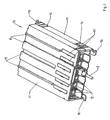
- connection module 4 shows a stack of four connection modules 10, 20, 30, consisting of two connection modules 10 for prefabricated copper cables 2, a connection module 20 for unassembled copper cables and a connection module 30 for fiber optic cables.
- the three lower connection modules 10, 20 are coupled by means of their lateral coupling devices 14.
- the connection module 30 is pushed, resulting in a stepped arrangement that leaves the number plate carrier of the lower connection module 10 remain visible.
Landscapes
- Coupling Device And Connection With Printed Circuit (AREA)
- Installation Of Indoor Wiring (AREA)
- Structure Of Telephone Exchanges (AREA)
- Connections Arranged To Contact A Plurality Of Conductors (AREA)
- Details Of Indoor Wiring (AREA)
- Connector Housings Or Holding Contact Members (AREA)
Description
- Die Erfindung betrifft Anschlussmodule für die Verteilung von Energie, Telekommunikation und/oder Daten gemäß dem Oberbegriff des Anspruchs 1.
- Für die flexible, flächendeckende Grundversorgung insbesondere von Büroarbeitsplätzen mit informations- und starkstromtechnischen Anschlüssen werden sogenannte Consolidation-Points eingesetzt. Es handelt sich dabei um Module, die mit einer Vielzahl von Steckbuchsen ausgerüstet sind, je nach Modultyp für Energie, für Telekommunikation oder für Daten. Die Anschlussmodule werden über fest verlegte Kabel mit der Gebäudeinstallation verbunden. Die Verbindung von den Anschlussmodulen zum Verbraucher erfolgt über fabrikmäßig vorkonfektionierte, mit Steckern versehene Kabel. Diese Vorgehensweise hat den Vorteil, dass die Verkabelung vor Ort von jedem Benutzer selbst vorgenommen werden kann. Ebenso sind Ergänzungen und Umrüstungen einfach und ohne großen Aufwand durchzuführen.
- Handelsübliche Anschlussmodule sind mit Kopplungsvorrichtungen ausgerüstet, die es ermöglichen, mehrere Module nebeneinander anzuordnen. Außerdem besitzen die Anschlussmodule Vorrichtungen, die ihre Befestigung an der Unterlage ermöglichen.
- Es sind des weiteren Anschlussmodule handelsüblich, die in spezielle Modulträger eingerastet werden müssen. Diese Modulträger ermöglichen die Montage der Module an der Unterlage, nebeneinander und auch übereinander. Aufgrund der Mehrzahl von Einzelteilen ist diese Konstruktion jedoch aufwändig.
- Relevantester Stand der Technik ist der
EP 1 176 673 A zu entnehmen. - Der vorliegenden Erfindung liegt die Aufgabe zugrunde, Anschlussmodule der eingangs genannten Art anzugeben, die ohne Zusatzelemente nebeneinander und übereinander befestigt werden können.
- Diese Aufgabe wird gelöst durch Anschlussmodule mit den Merkmalen des Anspruchs 1.
- Die vorliegende Erfindung verwendet vorgeformte Verbindungseinrichtungen nicht nur an den Seitenwänden der Module, sondern auch am Boden des Gehäuseunterteils und an der Oberseite des Gehäuseoberteils. Dabei sind die Verbindungseinrichtungen am Gehäuseoberteil von der Frontfläche des Moduls aus nach hinten versetzt, so dass sich ein gestufter Modulstapel ergibt. Diese stufenförmige Anordnung verbessert die Zugänglichkeit zu den diversen Steckbuchsen.
- Des weiteren gibt diese stufenförmige Stapelung der Module die Möglichkeit, auf der Oberseite des Gehäuses Kennzeichenträger anzuordnen, die den Steckdosen zugeordnet sind und die stets gut erkennbar bleiben.
- Gemäß einer besonderen Ausgestaltung der Erfindung sind die Anschlussmodule auch mit bodenseitigen Haltevorrichtungen ausgerüstet, die mit den entsprechenden Halteleisten am Boden von Kabelkanälen korrespondieren. Dadurch ergibt sich die Möglichkeit, die erfindungsgemäßen Anschlussmodule auch in Kabelkanälen einzusetzen.
- Weitere Ausgestaltungen der Erfindung ergeben sich aus den restlichen Unteransprüchen und aus den Ausführungsbeispielen, die anhand der Zeichnung erläutert werden sollen. Es zeigen jeweils in isometrischer Darstellung
- Fig. 1
- eine Ansicht der Frontseite eines Anschlussmoduls,
- Fig. 2
- eine Ansicht der Rückseite des Anschlussmoduls der Fig. 1,
- Fig. 3
- das Anschlussmodul der Fig. 1 und 2, eingesetzt in einen Kabelkanal, und
- Fig. 4
- einen Stapel von vier Anschlussmodulen.
- Fig. 1 und Fig. 2 zeigen zwei Ansichten eines Anschlussmoduls 10 für Telekommunikations- bzw. Datensignale. Man erkennt ein flaches, kubisches Gehäuse mit einem Unterteil 11 und einem abnehmbaren Oberteil 11'. In die Frontwand des Moduls 10 sind sechs Steckbuchsen 12 eingesetzt. Eine der Steckbuchsen 12 ist mit einem konfektionierten Datenkabel 2 bestückt.
- Auf der Oberseite des Gehäuses erkennt man Kennzeichenschilder 17, die jeweils einer Steckbuchse 12 zugeordnet sind. Dadurch ist eine eindeutige Beschriftung der Steckbuchsen 12 möglich.
- In die Seitenwände des Moduls 10 sind männliche und weibliche Koppeleinrichtungen 14 eingeformt, die es ermöglichen, mehrere Anschlussmodule 10 ohne Werkzeug nebeneinander anzuordnen.
- Weitere Verbindungsvorrichtungen 15 sind auch auf der Oberseite des Moduls 10 vorgesehen. Diese kooperieren mit entsprechenden Verbindungsvorrichtungen 18 (Fig. 3) an der Unterseite des Moduls 10. Dabei sind die Verbindungsvorrichtungen 15 an der Oberseite des Moduls 10 von der Frontwand aus gesehen hinter die Kennzeichenträger 17 nach hinten versetzt. Werden Module 10 übereinander gestapelt, so ergibt sich eine stufenförmige Anordnung, wie sie Fig. 4 zeigt.
- Zur Befestigung des Moduls 10 an einer Unterlage sind bodenseitig Füße 16 vorgesehen. Diese überragen die Frontwand bzw. die Rückwand nach vorne bzw. hinten, so dass sie das seitliche Anreihen weiterer Module nicht behindern und auch bei angereihten Modulen noch gut zugänglich sind.
- Wie Fig. 2 erkennen lässt, sind in der Rückwand Kabeleinführungsöffnungen 13 vorgesehen. Diese sind werksseitig zunächst geschlossen, können jedoch mit einem einfachen Werkzeug ausgebrochen werden, wenn an der betreffenden Stelle ein Kabel eingeführt werden soll. Die Kabeleinführungsöffnungen 13 sind so dimensioniert, dass sie gleichzeitig als Zugentlastung für die Kabel dienen.
- Fig. 3 zeigt das Anschlussmodul 10, eingesetzt in einen Kabelkanal 1. Kabelkanäle besitzen in aller Regel bodenseitige Halteleisten, an denen Trennwände, Einbaugeräte und dergleichen befestigt werden. Um das Anschlussmodul 10 an diesen Halteleisten befestigen zu können, ist am Boden des Moduls 10 eine geeignete Halteleiste 19 angeformt. Das Anschlussmodul 10 steht mit seinen bodenseitigen Verbindungsvorrichtungen 18 direkt auf dem Kanalboden.
- Fig. 4 zeigt einen Stapel von vier Anschlussmodulen 10, 20, 30, bestehend aus zwei Anschlussmodulen 10 für konfektionierte Kupferkabel 2, einem Anschlussmodul 20 für nicht konfektionierte Kupferkabel und einem Anschlussmodul 30 für Glasfaserkabel. Die drei unteren Anschlussmodule 10, 20 sind mit Hilfe ihrer seitlichen Koppelvorrichtungen 14 gekoppelt. Auf das mittlere Anschlussmodul 10 ist das Anschlussmodul 30 aufgeschoben, wobei sich eine stufenförmige Anordnung ergibt, die die Kennzeichenträger des unteren Anschlussmoduls 10 sichtbar bleiben lässt.
Claims (6)
- Anschlussmodul (10, 20, 30) für die Verteilung von Energie, Telekommunikation und/oder Daten im Doppelboden, in der Zwischendecke und/oder im Kabelkanal (1), im wesentlichen umfassend- ein kubisches Gehäuse mit Unterteil (11) und abnehmbarem Oberteil (11'),- Kabelanschlusseinrichtungen (12, 22, 32) in der Frontwand,- gegebenenfalls Kabel-Einführungsöffnungen (13) in der Rückwand,- Koppeleinrichtungen (14) an den Seitenwänden- und Haltevorrichtungen (16) zum Befestigen des Moduls (10, 20, 30) an einer Unterlage,gekennzeichnet durch die Merkmale:- am Unterteil (11) und am Oberteil (11') sind miteinander kooperierende Verbindungsvorrichtungen (15, 18) angeformt,- die oberteilseitigen Verbindungsvorrichtungen (15) sind von der Frontwand aus nach hinten versetzt.
- Anschlussmodul nach Anspruch 1, gekennzeichnet durch das Merkmal:- auf dem Oberteil (11') sind den Kabelanschlusseinrichtungen (12, 22, 32) zugeordnete Kennzeichenträger (17) angeordnet.
- Anschlussmodul nach Anspruch 1 oder 2, gekennzeichnet durch das Merkmal:- am Unterteil (11) sind Halteeinrichtungen (19) zur Befestigung am Boden eines Kabelkanals (1) vorgesehen.
- Anschlussmodul nach einem der Ansprüche 1 bis 3, gekennzeichnet durch das Merkmal:- in die Trennlinie der Rückwand sind ausbrechbare Zugentlastungen (13) eingeformt.
- Anschlussmodul nach einem der Ansprüche 1 bis 4, gekennzeichnet durch die Merkmale:- am Unterteil (11) sind Befestigungslaschen (16) angeformt,- die Befestigungslaschen (16) stehen über die Frontwand bzw. die Rückwand über.
- Anschlussmodul nach einem der Ansprüche 1 bis 5, gekennzeichnet durch das Merkmal:- die Kabelanschlusseinrichtungen sind als Steckdosen (12) für konfektionierte Kabel (2) ausgebildet.
Priority Applications (2)
| Application Number | Priority Date | Filing Date | Title |
|---|---|---|---|
| SI200530146T SI1555727T1 (sl) | 2004-01-15 | 2005-01-04 | Prikljucni modul |
| PL05000034T PL1555727T3 (pl) | 2004-01-15 | 2005-01-04 | Moduł przyłączeniowy |
Applications Claiming Priority (2)
| Application Number | Priority Date | Filing Date | Title |
|---|---|---|---|
| DE202004000525U DE202004000525U1 (de) | 2004-01-15 | 2004-01-15 | Anschlussmodul |
| DE202004000525U | 2004-01-15 |
Publications (3)
| Publication Number | Publication Date |
|---|---|
| EP1555727A2 EP1555727A2 (de) | 2005-07-20 |
| EP1555727A3 EP1555727A3 (de) | 2006-07-05 |
| EP1555727B1 true EP1555727B1 (de) | 2007-11-07 |
Family
ID=34609684
Family Applications (1)
| Application Number | Title | Priority Date | Filing Date |
|---|---|---|---|
| EP05000034A Expired - Lifetime EP1555727B1 (de) | 2004-01-15 | 2005-01-04 | Anschlussmodul |
Country Status (10)
| Country | Link |
|---|---|
| EP (1) | EP1555727B1 (de) |
| AT (1) | ATE377858T1 (de) |
| DE (2) | DE202004000525U1 (de) |
| DK (1) | DK1555727T3 (de) |
| ES (1) | ES2297539T3 (de) |
| HR (1) | HRP20080044T3 (de) |
| NO (1) | NO20050081L (de) |
| PL (1) | PL1555727T3 (de) |
| PT (1) | PT1555727E (de) |
| SI (1) | SI1555727T1 (de) |
Families Citing this family (5)
| Publication number | Priority date | Publication date | Assignee | Title |
|---|---|---|---|---|
| US7591677B2 (en) | 2006-04-21 | 2009-09-22 | Adc Telecommunications, Inc. | High density coaxial jack and panel |
| DE102007007008A1 (de) | 2007-02-08 | 2008-08-14 | Innova Solutions Gmbh | Vorrichtung zur Ausführung von Energie- und Datenkabeln aus Doppelböden |
| DE102008008258A1 (de) * | 2008-02-08 | 2009-08-13 | Leoni Kerpen Gmbh | Netzwerkmodul, für den Einbau in eine Verteilerperipherie |
| DE202009016290U1 (de) | 2009-12-01 | 2010-03-25 | Schulte-Elektrotechnik Gmbh & Co. Kg | Verteiler |
| CN108110533B (zh) * | 2017-12-20 | 2021-07-13 | 天津正迅泰科科技有限公司 | 一种计算机互联网接口防护装置及安装方法 |
Family Cites Families (5)
| Publication number | Priority date | Publication date | Assignee | Title |
|---|---|---|---|---|
| DE1537598A1 (de) * | 1967-11-25 | 1969-10-16 | Cannon Electric Gmbh | Dreipolige Klinke |
| US5122069A (en) * | 1989-07-28 | 1992-06-16 | Amp Incorporated | Access flooring module |
| DE19605698C1 (de) * | 1996-02-16 | 1997-04-24 | Wieland Elektrische Industrie | Anschlußeinrichtung für ein elektrisches Installationssystem |
| FR2799338B1 (fr) * | 1999-10-05 | 2001-11-30 | Sylea | Ensemble de modules pour la realisation de boites a fusibles |
| FR2812461A1 (fr) * | 2000-07-27 | 2002-02-01 | Cit Alcatel | Reglette de raccordement haute densite |
-
2004
- 2004-01-15 DE DE202004000525U patent/DE202004000525U1/de not_active Expired - Lifetime
-
2005
- 2005-01-04 PL PL05000034T patent/PL1555727T3/pl unknown
- 2005-01-04 ES ES05000034T patent/ES2297539T3/es not_active Expired - Lifetime
- 2005-01-04 AT AT05000034T patent/ATE377858T1/de not_active IP Right Cessation
- 2005-01-04 DE DE502005001851T patent/DE502005001851D1/de not_active Expired - Lifetime
- 2005-01-04 EP EP05000034A patent/EP1555727B1/de not_active Expired - Lifetime
- 2005-01-04 PT PT05000034T patent/PT1555727E/pt unknown
- 2005-01-04 SI SI200530146T patent/SI1555727T1/sl unknown
- 2005-01-04 DK DK05000034T patent/DK1555727T3/da active
- 2005-01-06 NO NO20050081A patent/NO20050081L/no not_active Application Discontinuation
-
2008
- 2008-01-25 HR HR20080044T patent/HRP20080044T3/xx unknown
Also Published As
| Publication number | Publication date |
|---|---|
| DE202004000525U1 (de) | 2005-05-25 |
| HRP20080044T3 (en) | 2008-02-29 |
| DE502005001851D1 (de) | 2007-12-20 |
| ES2297539T3 (es) | 2008-05-01 |
| EP1555727A2 (de) | 2005-07-20 |
| NO20050081L (no) | 2005-07-18 |
| ATE377858T1 (de) | 2007-11-15 |
| SI1555727T1 (sl) | 2008-04-30 |
| PL1555727T3 (pl) | 2008-03-31 |
| DK1555727T3 (da) | 2008-03-17 |
| NO20050081D0 (no) | 2005-01-06 |
| PT1555727E (pt) | 2008-02-06 |
| EP1555727A3 (de) | 2006-07-05 |
Similar Documents
| Publication | Publication Date | Title |
|---|---|---|
| EP3528023B1 (de) | Spleissmodul mit patcheinheit | |
| DE102008050700A1 (de) | Verteilerleiste und Geräteschrank | |
| EP1555727B1 (de) | Anschlussmodul | |
| DE202009009969U1 (de) | Verteilermodul und modulares Verteilerfeld | |
| DE3019412A1 (de) | Elektrische wandleiste | |
| EP0109568B1 (de) | Schrank oder Gerüst für die Aufnahme von Einschüben elektrischer Anlagen | |
| DE102015118338A1 (de) | Rangierfeldvorrichtung und Baukastensystem zur Herstellung einer Rangierfeldvorrichtung | |
| EP0174500B1 (de) | Mobile Wandung | |
| DE29818507U1 (de) | Verteilerschrank | |
| DE10325938B4 (de) | Kleinverteiler | |
| DE7736836U1 (de) | Arbeitstisch mit Kabelkanälen | |
| AT414286B (de) | Basisrahmen eines verteilers | |
| WO2019158725A1 (de) | Spleissmodul mit patcheinheit | |
| EP1050938A2 (de) | Netzanschluss-Tischgerät | |
| EP2749921B1 (de) | Verteileinrichtung für Lichtwellenleiter | |
| EP2863501B1 (de) | Verbindungselement, Kastenteil und Bausatz zur Bildung eines in eine Wandnische einzubauenden Kastens | |
| DE10064674C1 (de) | Anschlußeinheit für Arbeitsplatzrechner | |
| EP0626599B1 (de) | Verteilerschrank | |
| DE102005060894B3 (de) | PC und Peripherie Power Cable Box | |
| DE3727833A1 (de) | Gehaeuseeinheit zur aufnahme des hauptverteilers eines fernmelde-, insbesondere kommunikationssystems | |
| DE10313838A1 (de) | Zähler- und/oder Verteilerschrank | |
| DE102009052507A1 (de) | Zusatzgerätesystem für elektronische Stromzähler | |
| EP2757400B1 (de) | Glasfaser-Abschlusspunkt | |
| EP1536534A2 (de) | Anschlussmodul für Unterflurverkabelungen | |
| EP1079491A2 (de) | Gehäuse für eine Verteilerstation |
Legal Events
| Date | Code | Title | Description |
|---|---|---|---|
| PUAI | Public reference made under article 153(3) epc to a published international application that has entered the european phase |
Free format text: ORIGINAL CODE: 0009012 |
|
| AK | Designated contracting states |
Kind code of ref document: A2 Designated state(s): AT BE BG CH CY CZ DE DK EE ES FI FR GB GR HU IE IS IT LI LT LU MC NL PL PT RO SE SI SK TR |
|
| AX | Request for extension of the european patent |
Extension state: AL BA HR LV MK YU |
|
| PUAL | Search report despatched |
Free format text: ORIGINAL CODE: 0009013 |
|
| AK | Designated contracting states |
Kind code of ref document: A3 Designated state(s): AT BE BG CH CY CZ DE DK EE ES FI FR GB GR HU IE IS IT LI LT LU MC NL PL PT RO SE SI SK TR |
|
| AX | Request for extension of the european patent |
Extension state: AL BA HR LV MK YU |
|
| 17P | Request for examination filed |
Effective date: 20060923 |
|
| AKX | Designation fees paid |
Designated state(s): AT BE BG CH CY CZ DE DK EE ES FI FR GB GR HU IE IS IT LI LT LU MC NL PL PT RO SE SI SK TR |
|
| AXX | Extension fees paid |
Extension state: YU Payment date: 20060923 Extension state: MK Payment date: 20060923 Extension state: BA Payment date: 20060923 Extension state: LV Payment date: 20060923 Extension state: HR Payment date: 20060923 |
|
| GRAP | Despatch of communication of intention to grant a patent |
Free format text: ORIGINAL CODE: EPIDOSNIGR1 |
|
| GRAS | Grant fee paid |
Free format text: ORIGINAL CODE: EPIDOSNIGR3 |
|
| GRAA | (expected) grant |
Free format text: ORIGINAL CODE: 0009210 |
|
| AK | Designated contracting states |
Kind code of ref document: B1 Designated state(s): AT BE BG CH CY CZ DE DK EE ES FI FR GB GR HU IE IS IT LI LT LU MC NL PL PT RO SE SI SK TR |
|
| AX | Request for extension of the european patent |
Extension state: BA HR LV MK YU |
|
| REG | Reference to a national code |
Ref country code: GB Ref legal event code: FG4D Free format text: NOT ENGLISH |
|
| REG | Reference to a national code |
Ref country code: IE Ref legal event code: FG4D Free format text: LANGUAGE OF EP DOCUMENT: GERMAN |
|
| REG | Reference to a national code |
Ref country code: CH Ref legal event code: EP |
|
| REF | Corresponds to: |
Ref document number: 502005001851 Country of ref document: DE Date of ref document: 20071220 Kind code of ref document: P |
|
| REG | Reference to a national code |
Ref country code: HR Ref legal event code: TUEP Ref document number: P20080044 Country of ref document: HR |
|
| REG | Reference to a national code |
Ref country code: RO Ref legal event code: EPE |
|
| REG | Reference to a national code |
Ref country code: SE Ref legal event code: TRGR |
|
| REG | Reference to a national code |
Ref country code: PT Ref legal event code: SC4A Free format text: AVAILABILITY OF NATIONAL TRANSLATION Effective date: 20080124 |
|
| GBT | Gb: translation of ep patent filed (gb section 77(6)(a)/1977) |
Effective date: 20080206 |
|
| REG | Reference to a national code |
Ref country code: HR Ref legal event code: T1PR Ref document number: P20080044 Country of ref document: HR Ref country code: GR Ref legal event code: EP Ref document number: 20080400203 Country of ref document: GR Ref country code: CH Ref legal event code: NV Representative=s name: PATENTANWAELTE SCHAAD, BALASS, MENZL & PARTNER AG |
|
| REG | Reference to a national code |
Ref country code: DK Ref legal event code: T3 |
|
| REG | Reference to a national code |
Ref country code: PL Ref legal event code: T3 |
|
| REG | Reference to a national code |
Ref country code: ES Ref legal event code: FG2A Ref document number: 2297539 Country of ref document: ES Kind code of ref document: T3 |
|
| REG | Reference to a national code |
Ref country code: HU Ref legal event code: AG4A Ref document number: E002797 Country of ref document: HU |
|
| PGFP | Annual fee paid to national office [announced via postgrant information from national office to epo] |
Ref country code: BG Payment date: 20080109 Year of fee payment: 4 Ref country code: EE Payment date: 20080206 Year of fee payment: 4 Ref country code: HU Payment date: 20071229 Year of fee payment: 4 Ref country code: LT Payment date: 20080130 Year of fee payment: 4 Ref country code: MC Payment date: 20080121 Year of fee payment: 4 |
|
| PGFP | Annual fee paid to national office [announced via postgrant information from national office to epo] |
Ref country code: RO Payment date: 20071224 Year of fee payment: 4 |
|
| ET | Fr: translation filed | ||
| PLBE | No opposition filed within time limit |
Free format text: ORIGINAL CODE: 0009261 |
|
| STAA | Information on the status of an ep patent application or granted ep patent |
Free format text: STATUS: NO OPPOSITION FILED WITHIN TIME LIMIT |
|
| 26N | No opposition filed |
Effective date: 20080808 |
|
| PG25 | Lapsed in a contracting state [announced via postgrant information from national office to epo] |
Ref country code: CY Free format text: LAPSE BECAUSE OF FAILURE TO SUBMIT A TRANSLATION OF THE DESCRIPTION OR TO PAY THE FEE WITHIN THE PRESCRIBED TIME-LIMIT Effective date: 20071107 |
|
| LTLA | Lt: lapse of european patent or patent extension |
Effective date: 20090104 |
|
| PG25 | Lapsed in a contracting state [announced via postgrant information from national office to epo] |
Ref country code: MC Free format text: LAPSE BECAUSE OF NON-PAYMENT OF DUE FEES Effective date: 20090131 |
|
| REG | Reference to a national code |
Ref country code: EE Ref legal event code: MM4A Ref document number: E001881 Country of ref document: EE Effective date: 20090131 |
|
| PG25 | Lapsed in a contracting state [announced via postgrant information from national office to epo] |
Ref country code: EE Free format text: LAPSE BECAUSE OF NON-PAYMENT OF DUE FEES Effective date: 20090131 Ref country code: LT Free format text: LAPSE BECAUSE OF NON-PAYMENT OF DUE FEES Effective date: 20090104 |
|
| PG25 | Lapsed in a contracting state [announced via postgrant information from national office to epo] |
Ref country code: HU Free format text: LAPSE BECAUSE OF NON-PAYMENT OF DUE FEES Effective date: 20090105 |
|
| REG | Reference to a national code |
Ref country code: HR Ref legal event code: ODRP Ref document number: P20080044 Country of ref document: HR Payment date: 20091228 Year of fee payment: 6 |
|
| PGFP | Annual fee paid to national office [announced via postgrant information from national office to epo] |
Ref country code: CZ Payment date: 20091228 Year of fee payment: 6 Ref country code: SE Payment date: 20091222 Year of fee payment: 6 |
|
| PGFP | Annual fee paid to national office [announced via postgrant information from national office to epo] |
Ref country code: PL Payment date: 20091208 Year of fee payment: 6 Ref country code: SK Payment date: 20091228 Year of fee payment: 6 |
|
| PGFP | Annual fee paid to national office [announced via postgrant information from national office to epo] |
Ref country code: PT Payment date: 20091223 Year of fee payment: 6 |
|
| PG25 | Lapsed in a contracting state [announced via postgrant information from national office to epo] |
Ref country code: RO Free format text: LAPSE BECAUSE OF NON-PAYMENT OF DUE FEES Effective date: 20090104 |
|
| PGFP | Annual fee paid to national office [announced via postgrant information from national office to epo] |
Ref country code: CH Payment date: 20100125 Year of fee payment: 6 Ref country code: DK Payment date: 20100125 Year of fee payment: 6 Ref country code: ES Payment date: 20100122 Year of fee payment: 6 Ref country code: IE Payment date: 20100125 Year of fee payment: 6 Ref country code: IS Payment date: 20100129 Year of fee payment: 6 Ref country code: LU Payment date: 20100122 Year of fee payment: 6 |
|
| PGFP | Annual fee paid to national office [announced via postgrant information from national office to epo] |
Ref country code: FI Payment date: 20100122 Year of fee payment: 6 Ref country code: FR Payment date: 20100209 Year of fee payment: 6 Ref country code: IT Payment date: 20100123 Year of fee payment: 6 Ref country code: SI Payment date: 20091204 Year of fee payment: 6 |
|
| PGFP | Annual fee paid to national office [announced via postgrant information from national office to epo] |
Ref country code: AT Payment date: 20100120 Year of fee payment: 6 Ref country code: BE Payment date: 20100125 Year of fee payment: 6 Ref country code: DE Payment date: 20091216 Year of fee payment: 6 Ref country code: GB Payment date: 20100121 Year of fee payment: 6 |
|
| REG | Reference to a national code |
Ref country code: HR Ref legal event code: PBON Ref document number: P20080044 Country of ref document: HR Effective date: 20100105 |
|
| PGFP | Annual fee paid to national office [announced via postgrant information from national office to epo] |
Ref country code: NL Payment date: 20100121 Year of fee payment: 6 |
|
| PGFP | Annual fee paid to national office [announced via postgrant information from national office to epo] |
Ref country code: GR Payment date: 20100120 Year of fee payment: 6 |
|
| PG25 | Lapsed in a contracting state [announced via postgrant information from national office to epo] |
Ref country code: BG Free format text: LAPSE BECAUSE OF FAILURE TO SUBMIT A TRANSLATION OF THE DESCRIPTION OR TO PAY THE FEE WITHIN THE PRESCRIBED TIME-LIMIT Effective date: 20090131 |
|
| REG | Reference to a national code |
Ref country code: PT Ref legal event code: MM4A Free format text: LAPSE DUE TO NON-PAYMENT OF FEES Effective date: 20110704 |
|
| BERE | Be: lapsed |
Owner name: TEHALIT G.M.B.H. Effective date: 20110131 |
|
| REG | Reference to a national code |
Ref country code: NL Ref legal event code: V1 Effective date: 20110801 |
|
| REG | Reference to a national code |
Ref country code: DK Ref legal event code: EBP |
|
| REG | Reference to a national code |
Ref country code: CH Ref legal event code: PL |
|
| REG | Reference to a national code |
Ref country code: SE Ref legal event code: EUG |
|
| GBPC | Gb: european patent ceased through non-payment of renewal fee |
Effective date: 20110104 |
|
| REG | Reference to a national code |
Ref country code: SI Ref legal event code: KO00 Effective date: 20110829 |
|
| REG | Reference to a national code |
Ref country code: SK Ref legal event code: MM4A Ref document number: E 2992 Country of ref document: SK Effective date: 20110104 |
|
| REG | Reference to a national code |
Ref country code: FR Ref legal event code: ST Effective date: 20110930 |
|
| REG | Reference to a national code |
Ref country code: IE Ref legal event code: MM4A |
|
| PG25 | Lapsed in a contracting state [announced via postgrant information from national office to epo] |
Ref country code: CH Free format text: LAPSE BECAUSE OF NON-PAYMENT OF DUE FEES Effective date: 20110131 Ref country code: FR Free format text: LAPSE BECAUSE OF NON-PAYMENT OF DUE FEES Effective date: 20110131 Ref country code: PT Free format text: LAPSE BECAUSE OF NON-PAYMENT OF DUE FEES Effective date: 20110704 Ref country code: LI Free format text: LAPSE BECAUSE OF NON-PAYMENT OF DUE FEES Effective date: 20110131 |
|
| PGFP | Annual fee paid to national office [announced via postgrant information from national office to epo] |
Ref country code: TR Payment date: 20071213 Year of fee payment: 4 |
|
| PG25 | Lapsed in a contracting state [announced via postgrant information from national office to epo] |
Ref country code: CZ Free format text: LAPSE BECAUSE OF NON-PAYMENT OF DUE FEES Effective date: 20110104 Ref country code: GR Free format text: LAPSE BECAUSE OF NON-PAYMENT OF DUE FEES Effective date: 20110802 Ref country code: AT Free format text: LAPSE BECAUSE OF NON-PAYMENT OF DUE FEES Effective date: 20110104 Ref country code: FI Free format text: LAPSE BECAUSE OF NON-PAYMENT OF DUE FEES Effective date: 20110104 Ref country code: SK Free format text: LAPSE BECAUSE OF NON-PAYMENT OF DUE FEES Effective date: 20110104 Ref country code: BE Free format text: LAPSE BECAUSE OF NON-PAYMENT OF DUE FEES Effective date: 20110131 Ref country code: GB Free format text: LAPSE BECAUSE OF NON-PAYMENT OF DUE FEES Effective date: 20110104 Ref country code: SI Free format text: LAPSE BECAUSE OF NON-PAYMENT OF DUE FEES Effective date: 20110105 Ref country code: IS Free format text: LAPSE BECAUSE OF FAILURE TO SUBMIT A TRANSLATION OF THE DESCRIPTION OR TO PAY THE FEE WITHIN THE PRESCRIBED TIME-LIMIT Effective date: 20110801 |
|
| REG | Reference to a national code |
Ref country code: DE Ref legal event code: R119 Ref document number: 502005001851 Country of ref document: DE Effective date: 20110802 |
|
| PG25 | Lapsed in a contracting state [announced via postgrant information from national office to epo] |
Ref country code: NL Free format text: LAPSE BECAUSE OF NON-PAYMENT OF DUE FEES Effective date: 20110801 Ref country code: IT Free format text: LAPSE BECAUSE OF NON-PAYMENT OF DUE FEES Effective date: 20110104 |
|
| PG25 | Lapsed in a contracting state [announced via postgrant information from national office to epo] |
Ref country code: IE Free format text: LAPSE BECAUSE OF NON-PAYMENT OF DUE FEES Effective date: 20110104 |
|
| REG | Reference to a national code |
Ref country code: ES Ref legal event code: FD2A Effective date: 20120220 |
|
| PG25 | Lapsed in a contracting state [announced via postgrant information from national office to epo] |
Ref country code: ES Free format text: LAPSE BECAUSE OF NON-PAYMENT OF DUE FEES Effective date: 20110105 |
|
| REG | Reference to a national code |
Ref country code: PL Ref legal event code: LAPE |
|
| PG25 | Lapsed in a contracting state [announced via postgrant information from national office to epo] |
Ref country code: PL Free format text: LAPSE BECAUSE OF NON-PAYMENT OF DUE FEES Effective date: 20110104 |
|
| PG25 | Lapsed in a contracting state [announced via postgrant information from national office to epo] |
Ref country code: TR Free format text: LAPSE BECAUSE OF NON-PAYMENT OF DUE FEES Effective date: 20090104 |
|
| PG25 | Lapsed in a contracting state [announced via postgrant information from national office to epo] |
Ref country code: SE Free format text: LAPSE BECAUSE OF NON-PAYMENT OF DUE FEES Effective date: 20110105 |
|
| PG25 | Lapsed in a contracting state [announced via postgrant information from national office to epo] |
Ref country code: LU Free format text: LAPSE BECAUSE OF NON-PAYMENT OF DUE FEES Effective date: 20110104 |
|
| PG25 | Lapsed in a contracting state [announced via postgrant information from national office to epo] |
Ref country code: DE Free format text: LAPSE BECAUSE OF NON-PAYMENT OF DUE FEES Effective date: 20110802 |