EP1555633A2 - Multi-positional CT image producing method and x-ray CT apparatus - Google Patents
Multi-positional CT image producing method and x-ray CT apparatus Download PDFInfo
- Publication number
- EP1555633A2 EP1555633A2 EP04257986A EP04257986A EP1555633A2 EP 1555633 A2 EP1555633 A2 EP 1555633A2 EP 04257986 A EP04257986 A EP 04257986A EP 04257986 A EP04257986 A EP 04257986A EP 1555633 A2 EP1555633 A2 EP 1555633A2
- Authority
- EP
- European Patent Office
- Prior art keywords
- data
- ray
- reconstruction
- range
- view
- Prior art date
- Legal status (The legal status is an assumption and is not a legal conclusion. Google has not performed a legal analysis and makes no representation as to the accuracy of the status listed.)
- Withdrawn
Links
Images


Classifications
-
- A—HUMAN NECESSITIES
- A61—MEDICAL OR VETERINARY SCIENCE; HYGIENE
- A61B—DIAGNOSIS; SURGERY; IDENTIFICATION
- A61B6/00—Apparatus or devices for radiation diagnosis; Apparatus or devices for radiation diagnosis combined with radiation therapy equipment
- A61B6/02—Arrangements for diagnosis sequentially in different planes; Stereoscopic radiation diagnosis
- A61B6/03—Computed tomography [CT]
-
- G—PHYSICS
- G06—COMPUTING OR CALCULATING; COUNTING
- G06T—IMAGE DATA PROCESSING OR GENERATION, IN GENERAL
- G06T12/00—Tomographic reconstruction from projections
- G06T12/20—Inverse problem, i.e. transformations from projection space into object space
-
- A—HUMAN NECESSITIES
- A61—MEDICAL OR VETERINARY SCIENCE; HYGIENE
- A61B—DIAGNOSIS; SURGERY; IDENTIFICATION
- A61B6/00—Apparatus or devices for radiation diagnosis; Apparatus or devices for radiation diagnosis combined with radiation therapy equipment
- A61B6/02—Arrangements for diagnosis sequentially in different planes; Stereoscopic radiation diagnosis
- A61B6/027—Arrangements for diagnosis sequentially in different planes; Stereoscopic radiation diagnosis characterised by the use of a particular data acquisition trajectory, e.g. helical or spiral
Definitions
- the present invention relates to a multi-positional CT (computed tomography) image producing method and an X-ray CT apparatus, and more particularly to a CT image producing method and an X-ray CT apparatus capable of producing CT images at a plurality of positions in phase.
- a conventional technique for producing CT images at a plurality of slice positions by an axial scan comprises, for each slice position, conducting an axial scan with the slice position registered with a central detector row of a multi-row detector, collecting a data set in a required view range at the central detector row, reconstructing a CT image from the data set, and repeating these steps for the plurality of slice positions.
- a technique for producing CT images at a plurality of slice positions by a helical scan comprises, for each slice position, conducting a helical scan with the center of a scanned range registered with the slice position, collecting a data set in a required view range, reconstructing a CT image from the data set, and repeating these steps for the plurality of slice positions.
- an image reconstruction method and an X-ray CT apparatus for conducting a scan while rotating an X-ray tube and a multi-row detector around a subject to be imaged to collect data, generating a data set in a predetermined view range by extracting data of projection points formed by projecting pixels on a reconstruction plane onto a plane of the multi-row detector in a direction of X-ray transmission, and producing a CT image based on the data set (for example, see Patent Document 1).
- a three-dimensional backprojection method comprising: extracting projection data corresponding to a projection line(s) formed by projecting one line or a plurality of parallel lines at spacings of a plurality of pixels on an image reconstruction plane onto a plane of a multi-row detector in a direction of X-ray transmission; generating projection line data by multiplying the extracted projection data by a cone beam reconstruction weight; generating backprojected line data by filtering the projection line data; determining back-projected pixel data of each pixel on the reconstruction field based on the back-projected line data; and determining back-projected data by adding the back-projected pixel data on a pixel-by-pixel basis for all views used in image reconstruction (for example, see Japanese Patent Application Laid Open No. 2003-159244 and Japanese Patent Application Laid Open No. 2003-334188.)
- the present invention seeks to provide a CT image producing method and an X-ray CT apparatus capable of producing CT images at a plurality of positions in phase.
- the present invention provides a multi-positional CT image producing method characterized in comprising: collecting data in a predetermined scan range by a scan while making a relative rotation of at least one of an X-ray tube and a multi-row detector around a subject to be imaged or while making the relative rotation and a relative rectilinear motion of the X-ray tube and multi-row detector with respect to the subject to be imaged; extracting data of detector rows corresponding to reconstruction planes at a plurality of positions to generate respective data sets for the reconstruction planes in a predetermined view range; and producing respective CT images of the reconstruction planes based on said data sets.
- the phrase "relative rotation” includes: for a subject to be imaged placed in between the X-ray tube and multi-row detector, rotating at least one of the X-ray tube and multi-row detector around the subject to be imaged without rotating the subject to be imaged; rotating the subject to be imaged around its axis without rotating the X-ray tube and multi-row detector; and rotating the subject to be imaged around its axis and rotating at least one of the X-ray tube and multi-row detector around the subject to be imaged.
- the phrase "relative rectilinear motion” includes: for a subject to be imaged placed in between the X-ray tube and multi-row detector, rectilinearly moving the subject to be imaged (or the table on which the subject to be imaged is laid) without rectilinearly moving the X-ray tube and multi-row detector; rectilinearly moving the X-ray tube and multi-row detector without rectilinearly moving the subject to be imaged (or the table on which the subject to be imaged is laid); and rectilinearly moving the subject to be imaged (or the table on which the subject to be imaged is laid) and rectilinearly moving the X-ray tube and multi-row detector.
- the multi-positional CT image producing method of the first aspect since a plurality of CT images at different slice positions are produced from data collected by one axial scan or helical scan using a multi-row detector, the plurality of CT images can be made in phase.
- the present invention provides a multi-positional CT image producing method characterized in comprising: collecting data in a predetermined scan range by a scan while making a relative rotation of at least one of an X-ray tube and a multi-row detector around a subject to be imaged or while making the relative rotation and a relative rectilinear motion of the X-ray tube and multi-row detector with respect to the subject to be imaged; extracting data at projection points formed by projecting pixels on reconstruction planes at a plurality of positions onto a plane of the multi-row detector in a direction of X-ray transmission to generate respective data sets for the reconstruction planes in a predetermined view range; and producing respective CT images of the reconstruction planes based on said data sets.
- the multi-positional CT image producing method of the second aspect since a plurality of CT images at different slice positions are produced from data collected by one axial scan or helical scan using a multi-row detector, the plurality of CT images can be made in phase. Moreover, since the CT images are produced by extracting data of detector rows and channels onto which an X-ray beam passing through the pixels on the reconstruction planes impinges, cone angle artifacts are reduced.
- the present invention provides the multi-positional CT image producing method having the aforementioned configuration, characterized in comprising: producing the CT images by a three-dimensional image reconstruction technique.
- the Feldkamp method and the weighted Feldkamp method are known.
- the present invention provides the multi-positional CT image producing method having the aforementioned configuration, characterized in that said three-dimensional image reconstruction technique is a three-dimensional backprojection method comprising: extracting projection data corresponding to a projection line(s) formed by projecting one line or a plurality of parallel lines at spacings of a plurality of pixels on a reconstruction plane onto a plane of the multi-row detector in a direction of X-ray transmission; generating projection line data by multiplying said extracted projection data by a cone beam reconstruction weight; generating backprojected line data by filtering said projection line data; determining backprojected pixel data of each pixel on the reconstruction field based on said backprojected line data; and determining backprojected data by adding the backprojected pixel data on a pixel-by-pixel basis for all views used in image reconstruction.
- said three-dimensional image reconstruction technique is a three-dimensional backprojection method comprising: extracting projection data corresponding to a projection line(s) formed by projecting one line or a pluralit
- the angle between the line and direction of X-ray transmission is no less than about 45°, accuracy reduction can be prevented.
- the present invention provides the multi-positional CT image producing method having the aforementioned configuration, characterized in that: said scan range is a rotation angle range of at least "180° + fan beam angle.”
- the present invention provides the multi-positional CT image producing method having the aforementioned configuration, characterized in that: said view range is a rotation angle range of "180° + fan beam angle.”
- the multi-positional CT image producing method of the seventh aspect since the view range of the data set used in reconstruction of a CT image is small, temporal resolution is improved.
- the present invention provides the multi-positional CT image producing method having the aforementioned configuration, characterized in that: phase of motion of the subject to be imaged is detected based on cardiographic or respiratory signals.
- a CT image can be produced at a desired phase of the heart or lungs.
- the present invention provides an X-ray CT apparatus characterized in comprising: an X-ray tube; a multi-row detector; scanning means for collecting data in a predetermined scan range by a scan while making a relative rotation of at least one of said X-ray tube and said multi-row detector around a subject to be imaged or making the relative rotation and a relative rectilinear motion of said X-ray tube and said multi-row detector with respect to the subject to be imaged; data extracting means for extracting data of detector rows corresponding to reconstruction planes at a plurality of positions to generate respective data sets for the reconstruction planes in a predetermined view range; and image reconstruction means for producing respective CT images of the reconstruction planes based on said data sets.
- the multi-positional CT image producing method of the first aspect can be suitably implemented.
- the present invention provides an X-ray CT apparatus characterized in comprising: an X-ray tube; a multi-row detector; scanning means for collecting data in a predetermined scan range by a scan while making a relative rotation of at least one of said X-ray tube and said multi-row detector around a subject to be imaged or making the relative rotation and a relative rectilinear motion of said X-ray tube and said multi-row detector with respect to the subject to be imaged; data extracting means for extracting data at projection points formed by projecting pixels on reconstruction planes at a plurality of positions onto a plane of the multi-row detector in a direction of X-ray transmission to generate respective data sets for the reconstruction planes in a predetermined view range; and image reconstruction means for producing respective CT images of the reconstruction planes based on said data sets.
- the multi-positional CT image producing method of the second aspect can be suitably implemented.
- the present invention provides the X-ray CT apparatus having the aforementioned configuration, characterized in: producing the CT images by a three-dimensional image reconstruction technique.
- the multi-positional CT image producing method of the third aspect can be suitably implemented.
- the present invention provides the X-ray CT apparatus having the aforementioned configuration, characterized in that said three-dimensional image reconstruction technique is a three-dimensional back-projection method comprising: extracting projection data corresponding to a projection line(s) formed by projecting one line or a plurality of parallel lines at spacings of a plurality of pixels on a reconstruction plane onto a plane of the multi-row detector in a direction of X-ray transmission; generating projection line data by multiplying said extracted projection data by a cone beam reconstruction weight; generating back-projected line data by filtering said projection line data; determining back-projected pixel data of each pixel on the reconstruction field based on said back-projected line data; and determining back-projected data by adding the back-projected pixel data on a pixel-by-pixel basis for all views used in image reconstruction.
- said three-dimensional image reconstruction technique is a three-dimensional back-projection method comprising: extracting projection data corresponding to a projection line(s) formed by projecting one
- the multi-positional CT image producing method of the fourth aspect can be suitably implemented.
- the multi-positional CT image producing method of the fifth aspect can be suitably implemented.
- the present invention provides the X-ray CT apparatus having the aforementioned configuration, characterized in that: said scan range is a rotation angle range of at least "180° + fan beam angle.”
- the multi-positional CT image producing method of the sixth aspect can be suitably implemented.
- the present invention provides the X-ray CT apparatus having the aforementioned configuration, characterized in that: said view range is a rotation angle range of "180° + fan beam angle.”
- the multi-positional CT image producing method of the seventh aspect can be suitably implemented.
- the present invention provides the X-ray CT apparatus having the aforementioned configuration, characterized in that phase of motion of the subject to be imaged is detected based on cardiographic or respiratory signals.
- the multi-positional CT image producing method of the eighth aspect can be suitably implemented.
- CT images at a plurality of positions can be produced in phase.
- the multi-positional CT image producing method and X-ray CT apparatus of the present invention may be used in producing CT images of a plurality of cross sections and at the same phase of the heart.
- Figure 1 is a block configuration diagram showing an X-ray CT apparatus 100 of Example 1.
- the X-ray CT apparatus 100 comprises an operation console 1, a table apparatus 10, a scan gantry 20, and an electrocardiograph 40.
- the operation console 1 comprises an input device 2 for accepting inputs by a human operator, a central processing apparatus 3 for executing scan control processing, image reconstruction processing etc., a data collection buffer 5 for collecting data acquired at the scan gantry 20, a CRT 6 for displaying a produced CT image, and a storage device 7 for storing programs, data, and X-ray CT images.
- the table apparatus 10 comprises a table 12 for laying thereon a subject to be imaged and transporting the subject into/out of a bore (cavity portion) of the scan gantry 20.
- the table 12 is vertically and horizontally/rectilinearly moved by a motor incorporated in the table apparatus 10.
- the scan gantry 20 comprises an X-ray tube 21, an X-ray controller 22, a collimator 23, a multi-row detector 24, a DAS (data acquisition system) 25, a rotator-side controller 26 for controlling the X-ray controller 22, collimator 23 and DAS 25, an overall controller 29 for communicating control signals etc. with the operation console 1 and imaging table 10, and a slip ring 30.
- the electrocardiograph 40 detects cardiographic signals of the subject to be imaged.
- Figures 2 and 3 are explanatory diagrams of the X-ray tube 21 and multi-row detector 24.
- the X-ray tube 21 and multi-row detector 24 rotate around a center of rotation IC. Representing the direction of rectilinear motion of the table 12 as z-direction, a direction perpendicular to the upper surface of the table 12 as y-direction, and a direction orthogonal to the z- and y-directions as x-direction, a plane of rotation of the X-ray tube 21 and multi-row detector 24 is an x-y plane.
- the X-ray tube 21 generates an X-ray beam CB generally referred to as a cone beam.
- a view angle view 0° is defined.
- Figure 4 is a flow chart showing multi-positional CT image producing processing.
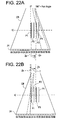
- Step S1 the operator specifies a plurality of slice positions. For example, as shown in Figure 22, a plurality of slice positions P1, P2, P3 and P4 across the heart of the subject to be imaged are specified. Moreover, the cardiac phase at which data are desired is specified.
- the operator specifies a scan range.
- a scan start angle and a scan end angle are specified.
- a scan start point Zs and a scan end point Ze are specified, as exemplarily illustrated in Figure 22. It should be noted that a wider scan range may be specified.
- Step S3 the X-ray CT apparatus 100 conducts a scan synchronously with the phase of cardiographic signals, and collects data.
- data D0( z , view, j, i ) represented by the z-position z, view angle view , detector row index j and channel index i is collected while rotating the X-ray tube 21 and multi-row detector 24 around the subject to be imaged without rectilinearly moving the table 12, or data D0( z , view, j, i ) represented by the rectilinear motion position z, view angle view, detector row index j and channel index i is collected while rotating the X-ray tube 21 and multi-row detector 24 around the subject to be imaged and rectilinearly moving the table 12.
- the rectilinear motion position z is obtained by an encoder counting a z-position pulse, converted into a z-coordinate at the overall controller 29, passed via the slip ring 30, and appended as z-coordinate information to the projection data from the DAS 25.
- Figure 5 shows a format of the data at a certain view angle view appended with the z-coordinate information.
- the X-ray CT apparatus 100 applies pre-processing (offset correction, log correction, X-ray dose correction and sensitivity correction) to the data D0( z , view, j, i ).
- Step S5 the X-ray CT apparatus 100 repeats Steps S51 and S52 for a plurality of slice positions.
- Step S51 the pre-processed data D0( z , view, j , i ) is subjected to three-dimensional backprojection processing to determine backprojected data D3( x , y ).
- Step S52 the backprojected data D3( x, y ) is subjected to post-processing to obtain a CT image.
- FIG 6 is a flow chart showing details of the three-dimensional backprojection processing (Step S51 in Figure 4).
- one view is taken as a view of interest in a view range needed in image reconstruction.
- the view range is, for example, "180° + fan angle” or "360°.”
- Step R2 projection data Dr corresponding to a plurality of parallel lines at spacings of a plurality of pixels on a reconstruction plane P are extracted from among the data D0( z , view, j , i ) at the view of interest.
- Figure 7 exemplarily shows a plurality of parallel lines L0 ⁇ L8 on the reconstruction plane P.
- the number of lines is 1/64 ⁇ 1/2 of the maximum number of pixels in the reconstruction plane in a direction orthogonal to the lines. For example, if the number of pixels in the reconstruction plane P is 512 ⁇ 512, the number of lines is nine.
- the line direction is defined as the x-direction for -45° ⁇ view ⁇ 45° (or a view angle range mainly including the range and also including its vicinity) and 135° ⁇ view ⁇ 225° (or a view angle range mainly including the range and also including its vicinity).
- the line direction is defined as the y-direction for 45° ⁇ view ⁇ 135° (or a view angle range mainly including the range and also including its vicinity) and 225° ⁇ view ⁇ 315° (or a view angle range mainly including the range and also including its vicinity).
- a projection plane pp is assumed to pass through the center of rotation IC and be parallel to the lines L0 ⁇ L8.
- Figure 8 shows lines T0 ⁇ T8 formed by projecting the plurality of parallel lines L0 ⁇ L8 on the reconstruction plane P onto a detector plane dp in a direction of X-ray transmission.
- the direction of X-ray transmission is determined based upon the geometry of the X-ray tube 21, multi-row detector 24 and lines L0 ⁇ L8.
- the projection data Dr corresponding to the lines L0 ⁇ L8 can be obtained by extracting data at the detector row j and channel i corresponding to the lines T0 ⁇ T8 projected onto the detector plane dp .
- the projection data Dr of the lines L0' ⁇ L8' on the projection plane pp are multiplied by a cone beam reconstruction weight to generate projection line data Dp on the projection plane pp as shown in Figure 10.
- the cone beam reconstruction weight is ( r 1/ r 0) 2 , where r 0 is the distance from the focal spot of the X-ray tube 21 to the j-th detector row and the i -th channel of the multi-row detector 24 corresponding to projection data Dr, and r 1 is the distance from the focal spot of the X-ray tube 21 to a point on the reconstruction plane P corresponding to the projection data Dr.
- the projection line data Dp on the projection plane pp are filtered. Specifically, the projection line data Dp on the projection plane pp are subjected to FFT, multiplied by a filter function (reconstruction function), and subjected to inverse FFT to generate image back-projected line data Df on the projection plane pp as shown in Figure 11.
- Step R5 the back-projected line data Df on the projection plane pp is interpolated in the line direction to generate high-density back-projected line data Dh on the projection plane pp as shown in Figure 12.
- the data density of the high-density back-projected line data Dh on the projection plane pp is 8 ⁇ 32 times the maximum number of pixels in the reconstruction plane P in the line direction. For example, if the factor is 16 and the number of pixels in the reconstruction plane P is 512x512, the data density is 8,192 points/line.
- Step R6 the high-density back-projected line data Dh on the projection plane pp are sampled and interpolated/extrapolated, if necessary, to generate back-projected pixel data D2 for pixels on the lines L0 ⁇ L8 on the reconstruction plane P, as shown in Figure 13.
- the high-density back-projected line data Dh are sampled and interpolated/extrapolated to generate back-projection data D2 for pixels in between the lines L0 ⁇ L8, as shown in Figure 14.
- the interpolation/extrapolation is conducted based on the back-projected pixel data D2 for pixels on the lines L0 ⁇ L8 on the reconstruction plane P to generate back-projected pixel data D2 for pixels in between the lines L0 ⁇ L8.
- Step R8 the back-projected pixel data D2 shown in Figure 14 or 20 are added on a pixel-by-pixel basis, as shown in Figure 21.
- Step R9 Steps R1 ⁇ R8 are repeated for all views needed in image reconstruction to obtain back-projected data D3(x, y ).
- Figure 22 is an explanatory diagram showing the relationship between a reconstruction plane P and a detector row in the multi-row detector 24.
- Data at views needed in image reconstruction of reconstruction planes P1, P2, P3 and P4 can be extracted from data of detector rows 4A ⁇ 8B.
- CT images are produced by extracting data of the detector rows and channels onto which an X-ray beam passing through pixels on the reconstruction planes P impinges, cone angle artifacts are reduced. If the X-ray beam passing through pixels on the reconstruction plane P falls outside the multi-row detector 24, data of a detector row and channel closest to the X-ray beam passing through the pixels on the reconstruction plane P may be used instead.
- the technique for image reconstruction may be a conventionally known three-dimensional image reconstruction technique according to the Feldkamp method.
- three-dimensional image reconstruction techniques proposed in Japanese Patent Application Nos. 2002-147061, 2002-147231, 2002-235561, 2002-235662, 2002-267833, 2002-322756 and 2002-338947 may be employed.
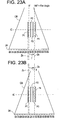
- CT images may be reconstructed from data sets generated by extracting data of detector rows straight below the reconstruction planes P1, P2, P3 and P4, without respect to the direction of X-ray beam transmission, as shown in Figure 23.
- Data may be collected by an axial scan rather than by a helical scan.
- the technique for image reconstruction may be a two-dimensional image reconstruction technique.
Landscapes
- Life Sciences & Earth Sciences (AREA)
- Health & Medical Sciences (AREA)
- Engineering & Computer Science (AREA)
- Medical Informatics (AREA)
- Physics & Mathematics (AREA)
- Optics & Photonics (AREA)
- General Health & Medical Sciences (AREA)
- High Energy & Nuclear Physics (AREA)
- Veterinary Medicine (AREA)
- Nuclear Medicine, Radiotherapy & Molecular Imaging (AREA)
- Public Health (AREA)
- Pathology (AREA)
- Radiology & Medical Imaging (AREA)
- Biomedical Technology (AREA)
- Heart & Thoracic Surgery (AREA)
- Molecular Biology (AREA)
- Surgery (AREA)
- Animal Behavior & Ethology (AREA)
- Biophysics (AREA)
- General Physics & Mathematics (AREA)
- Theoretical Computer Science (AREA)
- Apparatus For Radiation Diagnosis (AREA)
Abstract
Description
If the X-ray beam passing through pixels on the reconstruction plane P falls outside the
Claims (10)
- A multi-positional CT image producing method comprising the steps of: collecting data in a predetermined scan range by a scan while making a relative rotation of at least one of an X-ray tube (21) and a multi-row detector (24) around a subject to be imaged or while making the relative rotation and a relative rectilinear motion of the X-ray tube (21) and multi-row detector (24) with respect to the subject to be imaged; extracting data of detector rows corresponding to reconstruction planes at a plurality of positions to generate respective data sets for the reconstruction planes in a predetermined view range; and producing respective CT images of the reconstruction planes based on said data sets.
- A multi-positional CT image producing method comprising the steps of: collecting data in a predetermined scan range by a scan while making a relative rotation of at least one of an X-ray tube (21) and a multi-row detector (24) around a subject to be imaged or while making the relative rotation and a relative rectilinear motion of the X-ray tube (21) and multi-row detector (24) with respect to the subject to be imaged; extracting data at projection points formed by projecting pixels on reconstruction planes at a plurality of positions onto a plane of the multi-row detector (24) in a direction of X-ray transmission to generate respective data sets for the reconstruction planes in a predetermined view range; and producing respective CT images of the reconstruction planes based on said data sets.
- An X-ray CT apparatus (100) comprising: an X-ray tube (21); a multi-row detector (24); a scanning device (20) for collecting data in a predetermined scan range by a scan while making a relative rotation of at least one of said X-ray tube (21) and said multi-row detector (24) around a subject to be imaged or making the relative rotation and a relative rectilinear motion of said X-ray tube (21) and said multi-row detector (24) with respect to the subject to be imaged; a data extracting device (3) for extracting data of detector rows corresponding to reconstruction planes at a plurality of positions to generate respective data sets for the reconstruction planes in a predetermined view range; and an image reconstruction device (3) for producing respective CT images of the reconstruction planes based on said data sets.
- An X-ray CT apparatus (100) comprising: an X-ray tube (21); a multi-row detector (24); a scanning device (20) for collecting data in a predetermined scan range by a scan while making a relative rotation of at least one of said X-ray tube (21) and said multi-row detector (24) around a subject to be imaged or making the relative rotation and a relative rectilinear motion of said X-ray tube (21) and said multi-row detector (24) with respect to the subject to be imaged; a data extracting device (3) for extracting data at projection points formed by projecting pixels on reconstruction planes at a plurality of positions onto a plane of the multi-row detector (24) in a direction of X-ray transmission to generate respective data sets for the reconstruction planes in a predetermined view range; and an image reconstruction device (3) for producing respective CT images of the reconstruction planes based on said data sets.
- The X-ray CT apparatus (100) of claim 4, wherein: producing the CT images by a three-dimensional image reconstruction technique.
- The X-ray CT apparatus (100) of claim 5, wherein said three-dimensional image reconstruction technique is a three-dimensional back-projection method comprising the steps of: extracting projection data corresponding to a projection line(s) formed by projecting one line or a plurality of parallel lines at spacings of a plurality of pixels on a reconstruction plane onto a plane of the multi-row detector (24) in a direction of X-ray transmission; generating projection line data by multiplying said extracted projection data by a cone beam reconstruction weight; generating back-projected line data by filtering said projection line data; determining back-projected pixel data of each pixel on the reconstruction field based on said back-projected line data; and determining back-projected data by adding the back-projected pixel data on a pixel-by-pixel basis for all views used in image reconstruction.
- The X-ray CT apparatus (100) of claim 6, wherein: representing a direction perpendicular to a plane of rotation of the X-ray tube (21) and multi-row detector (24) or a direction of rectilinear motion in a helical scan as z-direction, a direction of the center axis of the X-ray beam at a view angle view = 0° as y-direction, and a direction orthogonal to the z- and y-directions as x-direction, the line direction is defined as the x-direction for -45° ≤ view < 45° or a view angle range mainly including the range and also including its vicinity and 135° ≤ view < 225° or a view angle range mainly including the range and also including its vicinity, and the line direction is defined as the y-direction for 45° ≤ view < 135° or a view angle range mainly including the range and also including its vicinity and 225° ≤ view < 315° or a view angle range mainly including the range and also including its vicinity.
- The X-ray CT apparatus (100) of any one of claims 3 ― 7, wherein said scan range is a rotation angle range of at least "180° + fan beam angle."
- The X-ray CT apparatus (100) of any one of claims 3 ― 8, wherein said view range is a rotation angle range of "180° + fan beam angle."
- The X-ray CT apparatus (100) of any one of claims 3 ― 9, wherein phase of motion of the subject to be imaged is detected based on cardiographic or respiratory signals.
Applications Claiming Priority (2)
| Application Number | Priority Date | Filing Date | Title |
|---|---|---|---|
| JP2003423898 | 2003-12-22 | ||
| JP2003423898A JP2005177203A (en) | 2003-12-22 | 2003-12-22 | Multi-position CT image generation method and X-ray CT apparatus |
Publications (2)
| Publication Number | Publication Date |
|---|---|
| EP1555633A2 true EP1555633A2 (en) | 2005-07-20 |
| EP1555633A3 EP1555633A3 (en) | 2005-11-09 |
Family
ID=34616808
Family Applications (1)
| Application Number | Title | Priority Date | Filing Date |
|---|---|---|---|
| EP04257986A Withdrawn EP1555633A3 (en) | 2003-12-22 | 2004-12-21 | Multi-positional CT image producing method and x-ray CT apparatus |
Country Status (5)
| Country | Link |
|---|---|
| US (1) | US7519144B2 (en) |
| EP (1) | EP1555633A3 (en) |
| JP (1) | JP2005177203A (en) |
| KR (1) | KR100733267B1 (en) |
| CN (1) | CN1647761B (en) |
Families Citing this family (4)
| Publication number | Priority date | Publication date | Assignee | Title |
|---|---|---|---|---|
| EP1913504B1 (en) * | 2005-08-03 | 2009-12-23 | Koninklijke Philips Electronics N.V. | Method and apparatus for generating multiple studies |
| JP2008000163A (en) * | 2006-06-20 | 2008-01-10 | Ge Medical Systems Global Technology Co Llc | X-ray ct apparatus |
| DE102011086226B3 (en) * | 2011-11-11 | 2013-01-17 | Bruker Optik Gmbh | Method for receiving spectrally resolved two-dimensional image by Fourier transform spectroscopy, involves feeding light to interferometer and splitting light into two partial-beams |
| JP6321405B2 (en) * | 2014-02-27 | 2018-05-09 | ジーイー・メディカル・システムズ・グローバル・テクノロジー・カンパニー・エルエルシー | Image generating apparatus, radiation tomography apparatus, image generating method, and program |
Family Cites Families (35)
| Publication number | Priority date | Publication date | Assignee | Title |
|---|---|---|---|---|
| US5838756A (en) * | 1996-01-08 | 1998-11-17 | Kabushiki Kaisha Toshiba | Radiation computed tomography apparatus |
| US5812628A (en) * | 1996-12-12 | 1998-09-22 | General Electric Company | Methods and apparatus for detecting partial volume image artifacts |
| JP3124254B2 (en) | 1997-07-24 | 2001-01-15 | ジーイー横河メディカルシステム株式会社 | Radiation tomography equipment |
| JP3174288B2 (en) | 1997-09-01 | 2001-06-11 | ジーイー横河メディカルシステム株式会社 | CT image creation method and X-ray CT apparatus |
| US6243437B1 (en) * | 1998-11-25 | 2001-06-05 | General Electric Company | Coronary calcification detection using retrospective cardiac gating of imaging system |
| US6275560B1 (en) * | 1998-12-22 | 2001-08-14 | General Electric Company | Cardiac gated computed tomography system |
| JP4378812B2 (en) * | 1999-11-19 | 2009-12-09 | 株式会社島津製作所 | Cone beam type radiation CT system |
| JP2001187046A (en) | 1999-12-27 | 2001-07-10 | Ge Medical Systems Global Technology Co Llc | Multi-slice x-ray ct device and method for controlling the same |
| US6301325B1 (en) | 1999-12-22 | 2001-10-09 | Ge Medical Systems Global Technology Company Llc | Half-scan algorithm for use with a high speed multi-row fan beam helical detector |
| US6442228B1 (en) | 2000-04-20 | 2002-08-27 | Ge Medical Systems Global Technology Company, Llc | Data acquisition modifications for improved reconstruction with conventional CT |
| US6539074B1 (en) | 2000-08-25 | 2003-03-25 | General Electric Company | Reconstruction of multislice tomographic images from four-dimensional data |
| EP1324699B1 (en) * | 2000-09-29 | 2009-03-25 | GE Medical Systems Global Technology Company LLC | Cardiac helical half scan reconstructions for multiple detector row ct |
| JP4652555B2 (en) | 2000-11-10 | 2011-03-16 | イビデン株式会社 | Catalytic converter, holding sealing material for catalytic converter |
| JP3458100B2 (en) | 2000-11-17 | 2003-10-20 | 繁雄 小川 | Snow eaves prevention device |
| DE10060291A1 (en) | 2000-12-05 | 2002-06-06 | Bosch Gmbh Robert | Butterfly valve for controlling air supply to IC engine has flap mounted on shaft whose ends fit into bores in casing wall, axial channels which are narrower than bores connecting them with rim of casing |
| JP3942142B2 (en) | 2000-12-15 | 2007-07-11 | ジーイー・メディカル・システムズ・グローバル・テクノロジー・カンパニー・エルエルシー | Radiation tomography apparatus and method |
| JP2002209884A (en) | 2000-12-26 | 2002-07-30 | Ge Medical Systems Global Technology Co Llc | X-ray ct instrument |
| US6463118B2 (en) | 2000-12-29 | 2002-10-08 | Ge Medical Systems Global Technology Company, Llc | Computed tomography (CT) weighting for high quality image recontruction |
| JP2002235561A (en) | 2001-02-08 | 2002-08-23 | Denso Corp | Throttle valve adjustment device |
| JP2002267833A (en) | 2001-03-14 | 2002-09-18 | Toray Ind Inc | A method for manufacturing a color filter for a liquid crystal display. |
| JP2002322756A (en) | 2001-04-27 | 2002-11-08 | Sekisui Chem Co Ltd | Roof structure, method of constructing the roof structure, and roof panel used for the roof structure |
| JP2002338947A (en) | 2001-05-15 | 2002-11-27 | Hitachi Kasei Polymer Co Ltd | One-package sealant |
| JP4610795B2 (en) | 2001-06-13 | 2011-01-12 | ジーイー・メディカル・システムズ・グローバル・テクノロジー・カンパニー・エルエルシー | Slice thickness determination method, slice thickness determination apparatus, program, and X-ray CT apparatus |
| US6990170B2 (en) * | 2001-08-09 | 2006-01-24 | Kabushiki Kaisha Toshiba | X-ray computed tomographic imaging apparatus |
| JP4175791B2 (en) | 2001-08-20 | 2008-11-05 | ジーイー・メディカル・システムズ・グローバル・テクノロジー・カンパニー・エルエルシー | Image generation method and X-ray CT apparatus |
| US7099503B2 (en) * | 2001-09-17 | 2006-08-29 | Ge Medical Systems Global Technology Llc | Image reconstruction method and X-ray CT apparatus |
| JP2003159244A (en) | 2001-09-17 | 2003-06-03 | Ge Medical Systems Global Technology Co Llc | Image reconstruction method and x-ray ct apparatus |
| US6526117B1 (en) * | 2001-11-09 | 2003-02-25 | Ge Medical Systems Global Technology Company, Llc | Method and apparatus to minimize phase misregistration artifacts in gated CT images |
| US6490333B1 (en) * | 2001-12-28 | 2002-12-03 | Ge Medical Systems Global Technology Company, Llc | Methods and apparatus for cone-tilted parallel sampling and reconstruction |
| JP3870105B2 (en) | 2002-02-22 | 2007-01-17 | ジーイー・メディカル・システムズ・グローバル・テクノロジー・カンパニー・エルエルシー | Back projection method and X-ray CT apparatus |
| JP4106251B2 (en) | 2002-03-12 | 2008-06-25 | ジーイー・メディカル・システムズ・グローバル・テクノロジー・カンパニー・エルエルシー | Three-dimensional backprojection method and X-ray CT apparatus |
| US6845144B2 (en) * | 2003-02-08 | 2005-01-18 | Ge Medical Systems Global Technology Company, Llc | Three dimensional back projection method and an X-ray CT apparatus |
| JP2005137390A (en) | 2003-11-04 | 2005-06-02 | Ge Medical Systems Global Technology Co Llc | CT image generation method and X-ray CT apparatus |
| JP4222930B2 (en) | 2003-12-10 | 2009-02-12 | ジーイー・メディカル・システムズ・グローバル・テクノロジー・カンパニー・エルエルシー | Three-dimensional backprojection method and apparatus and X-ray CT apparatus |
| JP4319109B2 (en) * | 2004-08-13 | 2009-08-26 | ジーイー・メディカル・システムズ・グローバル・テクノロジー・カンパニー・エルエルシー | Scan control method and X-ray CT apparatus |
-
2003
- 2003-12-22 JP JP2003423898A patent/JP2005177203A/en active Pending
-
2004
- 2004-12-20 US US11/017,014 patent/US7519144B2/en not_active Expired - Fee Related
- 2004-12-21 EP EP04257986A patent/EP1555633A3/en not_active Withdrawn
- 2004-12-22 KR KR1020040110111A patent/KR100733267B1/en not_active Expired - Fee Related
- 2004-12-22 CN CN2004100954980A patent/CN1647761B/en not_active Expired - Fee Related
Also Published As
| Publication number | Publication date |
|---|---|
| CN1647761A (en) | 2005-08-03 |
| US20050135549A1 (en) | 2005-06-23 |
| KR20050063728A (en) | 2005-06-28 |
| US7519144B2 (en) | 2009-04-14 |
| KR100733267B1 (en) | 2007-06-28 |
| CN1647761B (en) | 2012-06-13 |
| JP2005177203A (en) | 2005-07-07 |
| EP1555633A3 (en) | 2005-11-09 |
Similar Documents
| Publication | Publication Date | Title |
|---|---|---|
| JP4502426B2 (en) | Multi-slice imaging device | |
| JP4965433B2 (en) | Cone beam CT apparatus using truncated projection and pre-acquired 3D CT image | |
| JP6007386B2 (en) | Data processing device for radiation imaging | |
| JP3950782B2 (en) | Three-dimensional backprojection method and X-ray CT apparatus | |
| JP2007000406A (en) | X-ray ct method and x-ray ct apparatus | |
| JP2007307417A (en) | Image data processing method and image data processing apparatus | |
| JP2005013738A (en) | System and method for scanning an object in tomosynthesis applications | |
| US7173997B2 (en) | X-ray CT imaging method and X-ray CT apparatus | |
| JP2005040582A (en) | X-ray ct imaging method and x-ray ct apparatus | |
| EP1530163A2 (en) | CT image producing method and x-ray CT apparatus | |
| JP4509255B2 (en) | Perspective image creation method and apparatus | |
| JP2007097977A (en) | X-ray CT system | |
| US7519144B2 (en) | Multi-positional CT image producing method and X-ray CT apparatus | |
| JP5214110B2 (en) | X-ray CT system | |
| US7260175B2 (en) | CT image producing method and X-ray CT apparatus | |
| EP1542166B1 (en) | Three-dimension back-projection method and apparatus, and x-ray CT apparatus | |
| JP2000083948A (en) | Apparatus and method for making tomographic images | |
| JP2007159878A (en) | X-ray ct apparatus and method of reconstructing x-ray ct image of the same | |
| JP2008125909A (en) | X-ray ct apparatus | |
| JP4884649B2 (en) | X-ray CT system | |
| JP2003144431A (en) | Method for generating an image from measurement data by computed tomography | |
| JPH10155788A (en) | Computer tomography equipment | |
| JP2005137388A (en) | Ct image creation method and x-ray ct equipment |
Legal Events
| Date | Code | Title | Description |
|---|---|---|---|
| PUAI | Public reference made under article 153(3) epc to a published international application that has entered the european phase |
Free format text: ORIGINAL CODE: 0009012 |
|
| AK | Designated contracting states |
Kind code of ref document: A2 Designated state(s): AT BE BG CH CY CZ DE DK EE ES FI FR GB GR HU IE IS IT LI LT LU MC NL PL PT RO SE SI SK TR |
|
| AX | Request for extension of the european patent |
Extension state: AL BA HR LV MK YU |
|
| PUAL | Search report despatched |
Free format text: ORIGINAL CODE: 0009013 |
|
| AK | Designated contracting states |
Kind code of ref document: A3 Designated state(s): AT BE BG CH CY CZ DE DK EE ES FI FR GB GR HU IE IS IT LI LT LU MC NL PL PT RO SE SI SK TR |
|
| AX | Request for extension of the european patent |
Extension state: AL BA HR LV MK YU |
|
| 17P | Request for examination filed |
Effective date: 20060509 |
|
| AKX | Designation fees paid |
Designated state(s): DE FR GB |
|
| 17Q | First examination report despatched |
Effective date: 20060630 |
|
| STAA | Information on the status of an ep patent application or granted ep patent |
Free format text: STATUS: THE APPLICATION IS DEEMED TO BE WITHDRAWN |
|
| 18D | Application deemed to be withdrawn |
Effective date: 20090929 |