JP4509255B2 - Perspective image creation method and apparatus - Google Patents
Perspective image creation method and apparatus Download PDFInfo
- Publication number
- JP4509255B2 JP4509255B2 JP22701799A JP22701799A JP4509255B2 JP 4509255 B2 JP4509255 B2 JP 4509255B2 JP 22701799 A JP22701799 A JP 22701799A JP 22701799 A JP22701799 A JP 22701799A JP 4509255 B2 JP4509255 B2 JP 4509255B2
- Authority
- JP
- Japan
- Prior art keywords
- data
- image
- tomography apparatus
- weight
- weighted
- Prior art date
- Legal status (The legal status is an assumption and is not a legal conclusion. Google has not performed a legal analysis and makes no representation as to the accuracy of the status listed.)
- Expired - Lifetime
Links
- 238000000034 method Methods 0.000 title claims description 11
- 238000002591 computed tomography Methods 0.000 claims description 29
- 238000001914 filtration Methods 0.000 description 5
- 238000002594 fluoroscopy Methods 0.000 description 5
- 238000003384 imaging method Methods 0.000 description 5
- 238000010586 diagram Methods 0.000 description 4
- 229910052704 radon Inorganic materials 0.000 description 4
- SYUHGPGVQRZVTB-UHFFFAOYSA-N radon atom Chemical compound [Rn] SYUHGPGVQRZVTB-UHFFFAOYSA-N 0.000 description 4
- 238000005259 measurement Methods 0.000 description 3
- 230000002123 temporal effect Effects 0.000 description 3
- 230000015556 catabolic process Effects 0.000 description 2
- 238000006731 degradation reaction Methods 0.000 description 2
- 238000007689 inspection Methods 0.000 description 2
- 238000005070 sampling Methods 0.000 description 2
- 230000002238 attenuated effect Effects 0.000 description 1
- 230000005540 biological transmission Effects 0.000 description 1
- 238000001574 biopsy Methods 0.000 description 1
- 238000004364 calculation method Methods 0.000 description 1
- 230000001419 dependent effect Effects 0.000 description 1
- 230000005855 radiation Effects 0.000 description 1
Images


Classifications
-
- G—PHYSICS
- G06—COMPUTING; CALCULATING OR COUNTING
- G06T—IMAGE DATA PROCESSING OR GENERATION, IN GENERAL
- G06T11/00—2D [Two Dimensional] image generation
- G06T11/003—Reconstruction from projections, e.g. tomography
- G06T11/005—Specific pre-processing for tomographic reconstruction, e.g. calibration, source positioning, rebinning, scatter correction, retrospective gating
-
- G—PHYSICS
- G06—COMPUTING; CALCULATING OR COUNTING
- G06T—IMAGE DATA PROCESSING OR GENERATION, IN GENERAL
- G06T2211/00—Image generation
- G06T2211/40—Computed tomography
- G06T2211/428—Real-time
-
- Y—GENERAL TAGGING OF NEW TECHNOLOGICAL DEVELOPMENTS; GENERAL TAGGING OF CROSS-SECTIONAL TECHNOLOGIES SPANNING OVER SEVERAL SECTIONS OF THE IPC; TECHNICAL SUBJECTS COVERED BY FORMER USPC CROSS-REFERENCE ART COLLECTIONS [XRACs] AND DIGESTS
- Y10—TECHNICAL SUBJECTS COVERED BY FORMER USPC
- Y10S—TECHNICAL SUBJECTS COVERED BY FORMER USPC CROSS-REFERENCE ART COLLECTIONS [XRACs] AND DIGESTS
- Y10S378/00—X-ray or gamma ray systems or devices
- Y10S378/901—Computer tomography program or processor
Description
【0001】
【発明の属する技術分野】
本発明は画像作成技術に関するものであって、更に詳しく言えば、透視画像を作成する装置に関する。
【0002】
【従来の技術】
一般的にコンピュータ断層撮影(CT)装置と呼ばれる少なくとも1種の公知撮影装置においては、X線源から投射された扇形ビームが(一般に「撮影面」と呼ばれる)直交座標系のX−Y平面内に位置するようにコリメートされる。このX線ビームは撮影すべき被検体(たとえば患者)を通過する。被検体によって減弱させられた後、X線ビームは放射線検出器アレイに入射する。検出器アレイに入射するX線ビームの強度は、被検体によるX線ビームの減弱度に依存する。アレイ中の各々の検出器素子は独立の電気信号を生じるが、この電気信号はその検出器位置におけるX線ビーム減弱度の測定値である。全ての検出器素子からの減弱度測定値を個別に収集することによって透過プロフィールが得られる。
【0003】
公知の第三世代CT装置においては、X線源及び検出器アレイは撮影面内かつ撮影すべき被検体の周囲でガントリと共に回転する。その結果、X線ビームが被写体を横切る角度は絶えず変化する。あるガントリ角度において検出器アレイから得られる1群のX線ビーム減弱度測定値(すなわち、投影データ)は、「ビュー(view)」と呼ばれる。被検体の「スキャン(scan)」は、X線源及び検出器が1回転する間に様々なガントリ角度(又は視角)において得られたビューの集合から成っている。アキシャル(axial) 走査に際しては、投影データを処理することにより、被写体の二次元断面(スライス)に対応する画像が再構成される。投影データの集合から画像を再構成する方法の1つは、当業界においてフィルタ補正逆投影法と呼ばれるものである。この方法によれば、走査から得られた減弱度測定値が「CT数」又は「ハウンスフィールド(Hounsfield)単位」と呼ばれる整数に変換される。これらの整数を使用することにより、陰極線管ディスプレイ上の対応する画素の輝度が制御される。
【0004】
全走査時間を短縮するためには、「ヘリカル」走査を行えばよい。「ヘリカル」走査を行うためには、患者を移動させながら所定数の断面に関するデータを収集すればよい。かかる方式によれば、1つの扇形ビームによるヘリカル走査から1つの螺旋が作成される。扇形ビームによって規定された螺旋は投影データを生み出すが、それを用いて各々の所定断面中における画像を再構成することができる。
【0005】
CT透視装置においては、ヘリカル走査又はシネ走査によって収集されたデータを使用することにより、たとえば患者の内部の所望位置に針を案内するために役立つ連続した画像フレームを作成することができる。1つのフレームは、撮影された被検体の二次元断面に相当する。詳しく述べれば、投影データをフレーム・レートで処理することにより、被検体の画像フレームが作成される。
【0006】
【発明が解決しようとする課題】
公知のCT透視装置における一般的な目的は、画像の品質低下を最少限に抑えながらフレーム・レートを高めることにある。フレーム・レートを高めることは多くの利点をもたらすのであって、たとえば、手術を行う医師は生検用針の位置に関してより多くの情報を得ることができる。とは言え、フレーム・レートを高めることは画像の品質低下を最少限に抑えることと両立しないのが通例である。
【0007】
CT透視装置の時間遅れ(又は待ち時間)は、再構成アルゴリズムの性質に大きく依存する。たとえば、ある公知のCT透視装置の時間遅れはハーフスキャン画像再構成(HS)アルゴリズムの場合には小さいが、オーバースキャン画像再構成(OS)アルゴリズムの場合には大きい。OSアルゴリズムの場合には時間遅れが大きいとは言え、計算の複雑さを考慮してOSアルゴリズムが選ばれることもある。詳しく述べれば、OSアルゴリズムにおいて使用される重みはチャンネルに依存しないから、フィルタリング及び重み付けの順序を逆転することができる。その結果、データ集合を複数の部分集合に分割することができ、また各々の部分集合に関して2つの部分画像を作成することができる。その後、様々な部分画像を適当に組合わせることによって最終画像を得ることができる。
【0008】
ところで、このようなアプローチはHSアルゴリズムに拡張することができない。詳しく述べれば、ハーフスキャンの場合の重みはチャンネルに大きく依存する。それ故、フィルタリング及び重み付けの順序を逆転することができない。また、HSの重み関数は視角にも大きく依存する。そのため、前にフィルタリングし逆投影して得られたデータを次の画像の作成のために利用することができない。もし上記のOSアルゴリズムと同様な効率でハーフスキャン・アルゴリズムを実行することができれば、CT透視装置の時間的応答は顕著に向上させることができよう。
【0009】
【課題を解決するための手段】
上記及びその他の目的は、本発明の一態様に従えば、OSアルゴリズムに比べて時間的応答が向上するという利点に加えて満足すべき画像品質を与えるような修正ハーフスキャン画像再構成アルゴリズムを含むCT透視装置によって達成することができる。好ましい態様においては、かかるアルゴリズムはガントリ1回転当りの投影データ集合を所定数の部分集合に分割する工程を含んでいる。たとえば、部分集合の数は8であって、各々の部分集合は45度の角度範囲に広がる投影データを含む。投影データ集合を8つの部分集合に分割することにより、たとえば、毎秒8フレームという画像更新速度を達成することができる。各々の部分集合について2つの部分画像が作成される。すなわち、一方は第1の重みによって重み付けされたもの(Ti で表示する)であり、また他方は第2の重み(すなわち1)によって重み付けされたもの(Ui で表示する)である。最終画像(Pi )は下式に従って作成される。
【0010】
【数5】

式中、Nはガントリ1回転当りの各データ集合から分割される部分集合の数である。
【0012】
【発明の実施の形態】
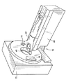
図1及び2について説明すれば、「第三世代」のCTスキャナを表わすガントリ12を含むコンピュータ断層撮影(CT)装置10が示されている。ガントリ12は、それの反対側に配置された検出器アレイ18に向けてX線ビーム16を投射するX線源14を含んでいる。検出器アレイ18は、患者22を通過した投射X線を同時に検知する検出器素子20から構成されている。各々の検出器素子20は電気信号を生じ、この電気信号は入射X線ビームの強度を表わし、従って患者22を通過した際のX線ビームの減弱度を表わす。X線投影データを得るための走査に際しては、ガントリ12及びその上に取付けられた構成部品が回転中心24の回りに回転する。
【0013】
ガントリ12の回転及びX線源14の動作は、CT装置10の制御機構26によって制御される。制御機構26は、X線源14に電力及びタイミング信号を供給するX線制御器28と、ガントリ12の回転速度及び位置を制御するガントリ・モータ制御器30とを含んでいる。制御機構26中のデータ収集装置(DAS)32は検出器素子20からアナログ・データをサンプリングし、そして以後の処理のためにかかるデータをディジタル信号に変換する。画像再構成装置34は、サンプリングされディジタル化されたX線データをDAS32から受信して、高速の画像再構成を行う。再構成された画像はコンピュータ36に入力として送られ、そして大容量記憶装置38中に保存される。
【0014】
コンピュータ36にはまた、キーボードを有する制御卓40を介して操作者から命令及び走査パラメータが送られる。付属した陰極線管ディスプレイ42により、操作者はコンピュータ36からの再構成画像及びその他のデータを観察することができる。操作者から送られる命令及びパラメータは、DAS32、X線制御器28及びガントリ・モータ制御器30に制御信号及び情報を供給するためにコンピュータ36によって使用される。更にまた、コンピュータ36は検査台モータ制御器44を動作させ、それによってガントリ12内に患者22を配置するための電動検査台46を制御する。詳しく述べれば、検査台46はガントリの開口48を通して患者22の各部を移動させる。
【0015】
ここに記載される画像再構成アルゴリズムは、通例、画像再構成装置34によって実行される。とは言え、かかるアルゴリズムは撮影装置のその他の構成要素(たとえばコンピュータ36)において実行することもできる。また、ここに記載された装置10は例示を目的としたものに過ぎないのであって、下記の画像再構成アルゴリズムはその他各種の撮影装置に関連しても実行し得ることを理解すべきである。
【0016】
図3は、HSサンプリング・パターンのラドン空間図を示している。上方及び下方の三角形の陰影部は、余分のサンプリング・ペアを表わしている。アーティファクトの無い再構成を保証するため、余分のサンプルには適当な重み付けを行う必要がある。かかる関数の一例を下記に示す。
【0017】
【数6】
ただし、
【0019】
【数7】
式中、γは、扇形ビーム中の特定の射線(ray) が、CT装置の等角点(isocenter) と交わる中心射線に対して成す角度であり、また、βはガントリ角度である。重みはチャンネルに大きく依存するから、投影データはフィルタリングの前に重み関数によって重み付けを行わなければならない。また、2つの三角形の陰影部は180度の投影視角範囲を占めている。すなわち、フィルタリング及び重み付けの動作のために切換えることができるのは投影データ集合全体の約20%に過ぎない。
【0021】
このような困難を克服するためには、高速CT透視画像再構成用の修正ハーフスキャン・アルゴリズム(MHS)を使用することができる。MHSに関するラドン空間は、図4に示されるごとくに分割される。2つの三角形の陰影部は、一様でない重みを有する元の視角範囲の半分しか占めない。
この場合の重みは下記の通りである。
【0022】
【数8】
直線β=γm−γ 及びβ=π+γm−γ の位置では、重み関数はγに関して微分可能でない。かかる不連続性によって引起こされる画像のアーティファクトを抑制するため、境界を横切ってフェザリング(feathering)を使用することができる。なお、不連続性に関係する画像のアーティファクトを抑制するためには、20チャネルのフェザリング距離で十分であると考えられる。
【0024】
MHSの重み関数は、下記の性質を有している。
【0025】
【数9】
それ故、上方の三角形の重みは、下方の三角形の重みを1から差引くことによって求めることができる。すなわち、上方の三角形の重みを有する部分画像を求めるためには、2つの部分画像を求めればよい。それらは、下方の三角形の重みによって重み付けされた部分画像、及び重み1によって重み付けされた部分画像である。これら2つの部分画像から求められる差分画像は、上方の三角形から直接に求められる部分画像と同一である。
【0027】
上記のごとき重み付けを考慮しつつ、下記の画像再構成アルゴリズムを使用することができる。詳しく述べれば、ガントリ1回転当りの投影データ集合が先ず8つの部分集合に分割される。その場合、各々の部分集合は45度の角度範囲に広がる投影データを含む。投影データ集合を8つの部分集合に分割することにより、毎秒8フレームという画像更新速度を達成することができる。代替的に、投影データ集合を60度の部分集合に分割することにより、毎秒6フレームの画像再構成速度を達成することもできるし、また所望のフレーム・レートに対応するその他の大きさの部分集合に分割することもできる。
【0028】
各々の部分集合に関し、2つの部分画像が作成される。一方は下方(又は上方)の三角形の重みによって重み付けされた部分画像(Ti で表示する)であり、また他方は重み1によって重み付けされた部分画像(Ui で表示する)である。最終画像(Pi) は 下記の式に従って作成することができる。
【0029】
【数10】
式中、Nは各データ集合から分割される部分集合の数である。
上記のごとき修正ハーフスキャン・アルゴリズムは、重み関数における対称性を利用したものであって、満足すべき画像品質を確保しながら毎秒8フレームの速度で画像の再構成を可能にする。その結果、かかる修正ハーフスキャン・アルゴリズムはCT透視用途におけるハーフスキャン重み付けの使用を可能にし、それにより、OSアルゴリズムに比べて時間的応答が向上するという利点に加えて、満足すべき画像品質を有する画像を作成することができる。
【0031】
本発明の様々な実施の態様に関する上記の説明によれば、本発明の目的が達成されることは明らかである。上記に本発明が詳しく記載されているとは言え、その説明は本発明の例示を目的としたものに過ぎないのであって、本発明の範囲を制限するものと解すべきでない。従って、本発明の範囲はもっぱら前記特許請求の範囲によって制限されることを理解すべきである。
【図面の簡単な説明】
【図1】CT装置の絵画的斜視図である。
【図2】図1に示された装置の概略ブロック図である。
【図3】元来のハーフスキャンに関するラドン空間図である。
【図4】修正されたハーフスキャンに関するラドン空間図である。
【符号の説明】
10 コンピュータ断層撮影装置
12 ガントリ
14 X線源
16 X線ビーム
18 検出器アレイ
20 検出器素子
22 患者
26 制御機構
28 X線制御器
30 ガントリ・モータ制御器
32 データ収集装置(DAS)
34 画像再構成装置
36 コンピュータ
38 大容量記憶装置
40 制御卓
42 陰極線管ディスプレイ
44 検査台モータ制御器
46 電動検査台[0001]
BACKGROUND OF THE INVENTION
The present invention relates to an image creation technique, and more particularly to an apparatus for creating a fluoroscopic image.
[0002]
[Prior art]
In at least one known imaging apparatus commonly referred to as a computed tomography (CT) apparatus, a fan beam projected from an X-ray source is within an XY plane of an orthogonal coordinate system (commonly referred to as an “imaging plane”). Collimated to be located in This X-ray beam passes through a subject to be imaged (for example, a patient). After being attenuated by the subject, the x-ray beam is incident on the radiation detector array. The intensity of the X-ray beam incident on the detector array depends on the degree of attenuation of the X-ray beam by the subject. Each detector element in the array produces an independent electrical signal, which is a measure of the x-ray beam attenuation at that detector location. A transmission profile is obtained by collecting attenuation measurements individually from all detector elements.
[0003]
In a known third generation CT apparatus, the X-ray source and detector array rotate with the gantry within the imaging plane and around the subject to be imaged. As a result, the angle at which the X-ray beam crosses the subject constantly changes. A group of x-ray beam attenuation measurements (ie projection data) obtained from a detector array at a certain gantry angle is called a “view”. A “scan” of an object consists of a collection of views taken at various gantry angles (or viewing angles) during one revolution of the x-ray source and detector. During axial scanning, the projection data is processed to reconstruct an image corresponding to a two-dimensional section (slice) of the subject. One method for reconstructing an image from a set of projection data is referred to in the art as the filtered backprojection method. According to this method, the attenuation measurement value obtained from the scan is converted into an integer called “CT number” or “Hounsfield unit”. By using these integers, the brightness of the corresponding pixels on the cathode ray tube display is controlled.
[0004]
In order to shorten the total scanning time, “helical” scanning may be performed. In order to perform a “helical” scan, data relating to a predetermined number of cross sections may be collected while moving the patient. According to this method, one spiral is created from helical scanning by one fan beam. The helix defined by the fan beam produces projection data that can be used to reconstruct the image in each predetermined section.
[0005]
In CT fluoroscopy, data collected by helical or cine scans can be used to create a series of image frames that serve, for example, to guide the needle to a desired location inside the patient. One frame corresponds to a two-dimensional section of the imaged subject. More specifically, an image frame of a subject is created by processing projection data at a frame rate.
[0006]
[Problems to be solved by the invention]
A general purpose in known CT fluoroscopy devices is to increase the frame rate while minimizing image quality degradation. Increasing the frame rate provides many advantages, for example, the surgeon performing the procedure can obtain more information regarding the position of the biopsy needle. However, increasing the frame rate is usually incompatible with minimizing image quality degradation.
[0007]
The time delay (or waiting time) of a CT fluoroscopy device depends largely on the nature of the reconstruction algorithm. For example, the time delay of a known CT fluoroscopy device is small for the half-scan image reconstruction (HS) algorithm but large for the over-scan image reconstruction (OS) algorithm. In the case of the OS algorithm, although the time delay is large, the OS algorithm may be selected in consideration of the complexity of calculation. Specifically, the weighting used in the OS algorithm is channel independent, so the order of filtering and weighting can be reversed. As a result, the data set can be divided into a plurality of subsets, and two partial images can be created for each subset. Thereafter, the final image can be obtained by appropriately combining various partial images.
[0008]
By the way, such an approach cannot be extended to the HS algorithm. More specifically, the weight in the case of half scan greatly depends on the channel. Therefore, the order of filtering and weighting cannot be reversed. In addition, the HS weighting function greatly depends on the viewing angle. Therefore, the data obtained by filtering and backprojecting before cannot be used for creating the next image. If the half-scan algorithm can be executed with the same efficiency as the OS algorithm described above, the temporal response of the CT fluoroscope will be significantly improved.
[0009]
[Means for Solving the Problems]
These and other objects include a modified half-scan image reconstruction algorithm that, in accordance with an aspect of the present invention, provides satisfactory image quality in addition to the advantage of improved temporal response compared to the OS algorithm. This can be achieved with a CT fluoroscope. In a preferred embodiment, such an algorithm includes dividing the projection data set per gantry rotation into a predetermined number of subsets. For example, the number of subsets is 8, and each subset includes projection data that spans a 45 degree angular range. By dividing the projection data set into 8 subsets, for example, an image update rate of 8 frames per second can be achieved. Two partial images are created for each subset. That is, one is weighted by a first weight (indicated by T i ) and the other is weighted by a second weight (ie 1) (indicated by U i ). The final image (P i ) is created according to the following formula.
[0010]
[Equation 5]
Where N is the number of subsets divided from each data set per gantry rotation.
[0012]
DETAILED DESCRIPTION OF THE INVENTION
1 and 2, a computed tomography (CT)
[0013]
The rotation of the
[0014]
Commands and scanning parameters are also sent to the
[0015]
The image reconstruction algorithm described herein is typically executed by the
[0016]
FIG. 3 shows a Radon space diagram of the HS sampling pattern. The shaded areas of the upper and lower triangles represent extra sampling pairs. To ensure reconstruction without artifacts, the extra samples need to be weighted appropriately. An example of such a function is shown below.
[0017]
[Formula 6]
However,
[0019]
[Expression 7]
Where γ is the angle formed by a particular ray in the fan beam with respect to the central ray that intersects the isocenter of the CT apparatus, and β is the gantry angle. Since the weight is highly dependent on the channel, the projection data must be weighted by a weight function before filtering. The shaded portions of the two triangles occupy a projection viewing angle range of 180 degrees. That is, only about 20% of the entire projection data set can be switched for filtering and weighting operations.
[0021]
To overcome such difficulties, a modified half-scan algorithm (MHS) for high-speed CT fluoroscopic image reconstruction can be used. The Radon space for MHS is divided as shown in FIG. The shadows of the two triangles occupy only half of the original viewing angle range with non-uniform weights.
The weights in this case are as follows.
[0022]
[Equation 8]
At the positions of the straight lines β = γ m −γ and β = π + γ m −γ, the weight function is not differentiable with respect to γ. To suppress image artifacts caused by such discontinuities, feathering can be used across the boundary. Note that a 20-channel feathering distance is considered sufficient to suppress image artifacts related to discontinuities.
[0024]
The weight function of MHS has the following properties.
[0025]
[Equation 9]
Therefore, the weight of the upper triangle can be determined by subtracting the weight of the lower triangle from 1. That is, in order to obtain a partial image having an upper triangular weight, two partial images may be obtained. They are the partial image weighted by the weight of the lower triangle and the partial image weighted by weight 1. The difference image obtained from these two partial images is the same as the partial image obtained directly from the upper triangle.
[0027]
The following image reconstruction algorithm can be used in consideration of the above weighting. More specifically, the projection data set per gantry rotation is first divided into eight subsets. In that case, each subset includes projection data extending over a 45 degree angle range. By dividing the projection data set into 8 subsets, an image update rate of 8 frames per second can be achieved. Alternatively, an image reconstruction rate of 6 frames per second can be achieved by dividing the projection data set into 60 degree subsets, and other sized parts corresponding to the desired frame rate. It can also be divided into sets.
[0028]
Two partial images are created for each subset. One is a partial image weighted by a lower (or upper) triangle weight (indicated by T i ), and the other is a partial image weighted by a weight of 1 (indicated by U i ). The final image (P i ) can be created according to the following formula:
[0029]
[Expression 10]
Where N is the number of subsets divided from each data set.
The modified half-scan algorithm as described above utilizes symmetry in the weighting function and allows image reconstruction at a rate of 8 frames per second while ensuring satisfactory image quality. As a result, such a modified half-scan algorithm allows the use of half-scan weighting in CT fluoroscopy applications, thereby having satisfactory image quality in addition to the advantage of improved temporal response compared to the OS algorithm. Images can be created.
[0031]
From the above description of various embodiments of the present invention, it is evident that the objects of the invention are attained. Although the invention has been described in detail above, the description is only for the purpose of illustrating the invention and should not be construed as limiting the scope of the invention. Accordingly, it should be understood that the scope of the present invention is limited solely by the scope of the appended claims.
[Brief description of the drawings]
FIG. 1 is a pictorial perspective view of a CT apparatus.
FIG. 2 is a schematic block diagram of the apparatus shown in FIG.
FIG. 3 is a radon space diagram related to an original half scan.
FIG. 4 is a Radon space diagram for a modified half scan.
[Explanation of symbols]
DESCRIPTION OF
34
Claims (10)
前記投影データの重み付けを行うため、前記プロセッサがガントリ1回転当りの投影データ集合を所定数の部分集合に分割するようにプログラムされている、コンピュータ断層撮影装置。It performs weighting of the projection data in accordance with the half scan weighting function having a symmetry and a processor programmed to generate image data for the resulting partial image from the weighted data seen including,
A computed tomography apparatus, wherein the processor is programmed to divide a projection data set per gantry rotation into a predetermined number of subsets for weighting the projection data.
w(γ,β)=1−w(γ,π+β)
によって表わされる条件を満足し、
ここで、γは、扇形ビーム中の特定の射線が、前記コンピュータ断層撮影装置のイソセンタと交わる中心射線に対して成す角度であり、
βはガントリ角度である、請求項1乃至5のいずれかに記載のコンピュータ断層撮影装置。The half scan weight function is expressed by the formula w (γ, β) = 1−w (γ, π + β)
It satisfies the condition represented by,
Here, γ is an angle formed by a specific ray in the fan beam with respect to a central ray intersecting with the isocenter of the computed tomography apparatus,
The β is a gantry angle, a computer tomography apparatus according to any one of claims 1 to 5.
対称性を有するハーフスキャン重み関数に従って投影データの重み付けを行う工程、及び得られた重み付きデータから部分画像用の画像データを作成する工程を含み、
少なくとも2つの部分画像が作成される場合において、1つの部分画像(Ti) に関するデータは第1の重みによって重み付けされ、かつ別の部分画像(Ui )に関するデータは第2の重みによって重み付けされる、方法。In a method for creating an image using data collected during fluoroscopic scanning,
The step of creating the image data of the partial image from the weighted data step to weight the projection data, and obtained according to the half scan weighting function having a symmetry seen including,
If at least two partial images are created, the data for one partial image (Ti) is weighted by a first weight and the data for another partial image (Ui) is weighted by a second weight , Method.
Applications Claiming Priority (2)
| Application Number | Priority Date | Filing Date | Title |
|---|---|---|---|
| US09/140,130 US6061423A (en) | 1998-08-25 | 1998-08-25 | Fluoroscopy image reconstruction |
| US09/140130 | 1998-08-25 |
Publications (2)
| Publication Number | Publication Date |
|---|---|
| JP2000070257A JP2000070257A (en) | 2000-03-07 |
| JP4509255B2 true JP4509255B2 (en) | 2010-07-21 |
Family
ID=22489890
Family Applications (1)
| Application Number | Title | Priority Date | Filing Date |
|---|---|---|---|
| JP22701799A Expired - Lifetime JP4509255B2 (en) | 1998-08-25 | 1999-08-11 | Perspective image creation method and apparatus |
Country Status (4)
| Country | Link |
|---|---|
| US (1) | US6061423A (en) |
| EP (1) | EP0989521B1 (en) |
| JP (1) | JP4509255B2 (en) |
| IL (1) | IL131376A (en) |
Families Citing this family (13)
| Publication number | Priority date | Publication date | Assignee | Title |
|---|---|---|---|---|
| JP3368838B2 (en) * | 1998-08-06 | 2003-01-20 | 株式会社島津製作所 | X-ray CT system |
| US6243437B1 (en) * | 1998-11-25 | 2001-06-05 | General Electric Company | Coronary calcification detection using retrospective cardiac gating of imaging system |
| US6778689B1 (en) | 2000-03-29 | 2004-08-17 | General Electric Company | System and method of real-time multiple field-of-view imaging |
| JP4538142B2 (en) * | 2000-09-06 | 2010-09-08 | 株式会社日立メディコ | Tomographic image creating method and tomographic image creating apparatus. |
| US6917663B2 (en) * | 2003-06-16 | 2005-07-12 | Kabushiki Kaisha Toshiba | Cone-beam reconstruction apparatus and computed tomography apparatus |
| EP1639547A2 (en) | 2003-06-18 | 2006-03-29 | Philips Intellectual Property & Standards GmbH | Computer tomography method using redundant measured values |
| JP4509507B2 (en) * | 2003-08-20 | 2010-07-21 | ジーイー・メディカル・システムズ・グローバル・テクノロジー・カンパニー・エルエルシー | Radiation calculation tomographic image apparatus and tomographic image generation method |
| US20060056729A1 (en) * | 2004-09-15 | 2006-03-16 | Hillis W D | Fourier domain camera |
| US7734079B2 (en) * | 2004-09-28 | 2010-06-08 | General Electric Company | Methods and apparatus for image reconstruction |
| EP1885247A1 (en) | 2005-05-12 | 2008-02-13 | Philips Intellectual Property & Standards GmbH | Continuous computer tomography performing super-short-scans and stronger weighting of most recent data |
| US7570733B2 (en) * | 2005-06-10 | 2009-08-04 | General Electric Company | Step-and-shoot cardiac CT imaging |
| WO2015111052A1 (en) * | 2014-01-23 | 2015-07-30 | Yissum Research Development Company Of The Hebrew University Of Jerusalem Ltd. | Method of repeat computer tomography scanning and system thereof |
| CN107004282B (en) * | 2014-11-26 | 2020-10-23 | 阿里内塔有限公司 | Image reconstruction method for computer tomography |
Citations (2)
| Publication number | Priority date | Publication date | Assignee | Title |
|---|---|---|---|---|
| JPH08196533A (en) * | 1995-01-31 | 1996-08-06 | Toshiba Corp | X-ray computer tomograph |
| JPH08299326A (en) * | 1995-05-02 | 1996-11-19 | Toshiba Corp | Computer tomograph |
Family Cites Families (6)
| Publication number | Priority date | Publication date | Assignee | Title |
|---|---|---|---|---|
| JP3006722B2 (en) * | 1991-02-22 | 2000-02-07 | 株式会社東芝 | Computer tomography equipment |
| JP3285944B2 (en) * | 1992-08-12 | 2002-05-27 | 株式会社東芝 | Computer tomography equipment |
| JP3090400B2 (en) * | 1994-04-05 | 2000-09-18 | 東芝医用システムエンジニアリング株式会社 | Computer tomography equipment |
| JP3735390B2 (en) * | 1995-01-31 | 2006-01-18 | 株式会社東芝 | X-ray computed tomography system |
| US5708690A (en) | 1996-10-11 | 1998-01-13 | General Electric Company | Methods and apparatus for helical image reconstruction in a computed tomography fluoro system |
| US5907593A (en) * | 1997-11-26 | 1999-05-25 | General Electric Company | Image reconstruction in a CT fluoroscopy system |
-
1998
- 1998-08-25 US US09/140,130 patent/US6061423A/en not_active Expired - Lifetime
-
1999
- 1999-08-11 JP JP22701799A patent/JP4509255B2/en not_active Expired - Lifetime
- 1999-08-12 IL IL13137699A patent/IL131376A/en not_active IP Right Cessation
- 1999-08-20 EP EP99306581A patent/EP0989521B1/en not_active Expired - Lifetime
Patent Citations (2)
| Publication number | Priority date | Publication date | Assignee | Title |
|---|---|---|---|---|
| JPH08196533A (en) * | 1995-01-31 | 1996-08-06 | Toshiba Corp | X-ray computer tomograph |
| JPH08299326A (en) * | 1995-05-02 | 1996-11-19 | Toshiba Corp | Computer tomograph |
Also Published As
| Publication number | Publication date |
|---|---|
| US6061423A (en) | 2000-05-09 |
| EP0989521A2 (en) | 2000-03-29 |
| IL131376A (en) | 2004-06-01 |
| EP0989521A3 (en) | 2010-05-05 |
| EP0989521B1 (en) | 2013-03-13 |
| JP2000070257A (en) | 2000-03-07 |
| IL131376A0 (en) | 2001-01-28 |
Similar Documents
| Publication | Publication Date | Title |
|---|---|---|
| JP4367884B2 (en) | Method and apparatus for leveling calcification | |
| US6452996B1 (en) | Methods and apparatus utilizing generalized helical interpolation algorithm | |
| JP4644785B2 (en) | Method and apparatus for reducing artifacts in cone beam CT image reconstruction | |
| JP4384749B2 (en) | Artifact correction for highly attenuating objects | |
| US5663995A (en) | Systems and methods for reconstructing an image in a CT system performing a cone beam helical scan | |
| US6266388B1 (en) | Methods and apparatus for two-pass cone beam image reconstruction | |
| US5606585A (en) | Methods and apparatus for multislice helical image reconstruction in a computer tomography system | |
| US6285732B1 (en) | Methods and apparatus for adaptive interpolation reduced view CT scan | |
| US6341154B1 (en) | Methods and apparatus for fast CT imaging helical weighting | |
| IL124014A (en) | Methods and apparatus for scanning an object in a computed tomography system | |
| JP2007307417A (en) | Method and apparatus for image data processing | |
| JP2003210452A (en) | Method and apparatus for cone-tilted parallel sampling and reconstruction | |
| JP4509255B2 (en) | Perspective image creation method and apparatus | |
| EP1372115B1 (en) | Methods and apparatus for reconstructing an image of an object | |
| JP4718702B2 (en) | X-ray computed tomography system | |
| JP2004160218A (en) | X-ray computerized tomographic apparatus, x-ray computerized tomographic apparatus control method, and x-ray computerized tomography program | |
| US6269139B1 (en) | Methods and apparatus for pre-filtering weighting in image reconstruction | |
| JP4676641B2 (en) | Method and apparatus for helical reconstruction of multi-slice CT scan | |
| JPH09182745A (en) | Computer tomographic device | |
| US6507632B1 (en) | Method and apparatus for reducing artifacts in an image | |
| US6647084B1 (en) | Method and apparatus for filtering projection data of a helical scan | |
| US20080086052A1 (en) | Methods and apparatus for motion compensation | |
| JP4356061B2 (en) | Method and apparatus for weighting projection data | |
| JP2002065663A (en) | Method and apparatus to reversibly impose imaging data | |
| US6327325B1 (en) | Methods and apparatus for adaptive interpolation reduced view CT scan |
Legal Events
| Date | Code | Title | Description |
|---|---|---|---|
| A621 | Written request for application examination |
Free format text: JAPANESE INTERMEDIATE CODE: A621 Effective date: 20060808 |
|
| A131 | Notification of reasons for refusal |
Free format text: JAPANESE INTERMEDIATE CODE: A131 Effective date: 20090526 |
|
| A521 | Request for written amendment filed |
Free format text: JAPANESE INTERMEDIATE CODE: A523 Effective date: 20090723 |
|
| RD02 | Notification of acceptance of power of attorney |
Free format text: JAPANESE INTERMEDIATE CODE: A7422 Effective date: 20090723 |
|
| RD04 | Notification of resignation of power of attorney |
Free format text: JAPANESE INTERMEDIATE CODE: A7424 Effective date: 20090723 |
|
| A131 | Notification of reasons for refusal |
Free format text: JAPANESE INTERMEDIATE CODE: A131 Effective date: 20100112 |
|
| A521 | Request for written amendment filed |
Free format text: JAPANESE INTERMEDIATE CODE: A523 Effective date: 20100302 |
|
| A521 | Request for written amendment filed |
Free format text: JAPANESE INTERMEDIATE CODE: A523 Effective date: 20100308 |
|
| TRDD | Decision of grant or rejection written | ||
| A01 | Written decision to grant a patent or to grant a registration (utility model) |
Free format text: JAPANESE INTERMEDIATE CODE: A01 Effective date: 20100406 |
|
| A01 | Written decision to grant a patent or to grant a registration (utility model) |
Free format text: JAPANESE INTERMEDIATE CODE: A01 |
|
| A61 | First payment of annual fees (during grant procedure) |
Free format text: JAPANESE INTERMEDIATE CODE: A61 Effective date: 20100428 |
|
| FPAY | Renewal fee payment (event date is renewal date of database) |
Free format text: PAYMENT UNTIL: 20130514 Year of fee payment: 3 |
|
| R150 | Certificate of patent or registration of utility model |
Ref document number: 4509255 Country of ref document: JP Free format text: JAPANESE INTERMEDIATE CODE: R150 Free format text: JAPANESE INTERMEDIATE CODE: R150 |
|
| FPAY | Renewal fee payment (event date is renewal date of database) |
Free format text: PAYMENT UNTIL: 20140514 Year of fee payment: 4 |
|
| R250 | Receipt of annual fees |
Free format text: JAPANESE INTERMEDIATE CODE: R250 |
|
| R250 | Receipt of annual fees |
Free format text: JAPANESE INTERMEDIATE CODE: R250 |
|
| R250 | Receipt of annual fees |
Free format text: JAPANESE INTERMEDIATE CODE: R250 |
|
| R250 | Receipt of annual fees |
Free format text: JAPANESE INTERMEDIATE CODE: R250 |
|
| R250 | Receipt of annual fees |
Free format text: JAPANESE INTERMEDIATE CODE: R250 |
|
| R250 | Receipt of annual fees |
Free format text: JAPANESE INTERMEDIATE CODE: R250 |
|
| R250 | Receipt of annual fees |
Free format text: JAPANESE INTERMEDIATE CODE: R250 |
|
| EXPY | Cancellation because of completion of term |