EP1555522B1 - Verfahren und Gerät zur Charakerisierung einer Kontaktfläche, z. B. einer Kunststoffrasenfläche - Google Patents
Verfahren und Gerät zur Charakerisierung einer Kontaktfläche, z. B. einer Kunststoffrasenfläche Download PDFInfo
- Publication number
- EP1555522B1 EP1555522B1 EP04425022A EP04425022A EP1555522B1 EP 1555522 B1 EP1555522 B1 EP 1555522B1 EP 04425022 A EP04425022 A EP 04425022A EP 04425022 A EP04425022 A EP 04425022A EP 1555522 B1 EP1555522 B1 EP 1555522B1
- Authority
- EP
- European Patent Office
- Prior art keywords
- weight
- deformation energy
- restitution
- falling
- parameter
- Prior art date
- Legal status (The legal status is an assumption and is not a legal conclusion. Google has not performed a legal analysis and makes no representation as to the accuracy of the status listed.)
- Expired - Lifetime
Links
Images

Classifications
-
- G—PHYSICS
- G01—MEASURING; TESTING
- G01N—INVESTIGATING OR ANALYSING MATERIALS BY DETERMINING THEIR CHEMICAL OR PHYSICAL PROPERTIES
- G01N3/00—Investigating strength properties of solid materials by application of mechanical stress
- G01N3/40—Investigating hardness or rebound hardness
- G01N3/48—Investigating hardness or rebound hardness by performing impressions under impulsive load by indentors, e.g. falling ball
-
- G—PHYSICS
- G01—MEASURING; TESTING
- G01N—INVESTIGATING OR ANALYSING MATERIALS BY DETERMINING THEIR CHEMICAL OR PHYSICAL PROPERTIES
- G01N33/00—Investigating or analysing materials by specific methods not covered by groups G01N1/00 - G01N31/00
- G01N33/0078—Testing material properties on manufactured objects
- G01N33/008—Sport articles, e.g. balls, skis or rackets
-
- G—PHYSICS
- G01—MEASURING; TESTING
- G01N—INVESTIGATING OR ANALYSING MATERIALS BY DETERMINING THEIR CHEMICAL OR PHYSICAL PROPERTIES
- G01N2203/00—Investigating strength properties of solid materials by application of mechanical stress
- G01N2203/0001—Type of application of the stress
- G01N2203/001—Impulsive
-
- G—PHYSICS
- G01—MEASURING; TESTING
- G01N—INVESTIGATING OR ANALYSING MATERIALS BY DETERMINING THEIR CHEMICAL OR PHYSICAL PROPERTIES
- G01N2203/00—Investigating strength properties of solid materials by application of mechanical stress
- G01N2203/0014—Type of force applied
- G01N2203/0016—Tensile or compressive
- G01N2203/0019—Compressive
-
- G—PHYSICS
- G01—MEASURING; TESTING
- G01N—INVESTIGATING OR ANALYSING MATERIALS BY DETERMINING THEIR CHEMICAL OR PHYSICAL PROPERTIES
- G01N2203/00—Investigating strength properties of solid materials by application of mechanical stress
- G01N2203/003—Generation of the force
- G01N2203/0032—Generation of the force using mechanical means
- G01N2203/0033—Weight
-
- G—PHYSICS
- G01—MEASURING; TESTING
- G01N—INVESTIGATING OR ANALYSING MATERIALS BY DETERMINING THEIR CHEMICAL OR PHYSICAL PROPERTIES
- G01N33/00—Investigating or analysing materials by specific methods not covered by groups G01N1/00 - G01N31/00
- G01N33/24—Earth materials
Definitions
- the present invention relates to techniques for the characterization of treading surfaces.
- the standard DIN 18035/7 envisages specific criteria for measuring and calculating a parameter of absorption of energy KA (abbreviation of the German word Kraftabbau), which can be detected using an apparatus known as "artificial athlete of Berlin".
- KA absorption of energy
- FIFA International Federation of Football Association
- the weight is dropped from a given height onto the surface, and associated to the structure is a cup sustained by a spring, which will be struck by the weight as it falls.
- the weight will strike the surface to be characterized at the end of its fall: in this case the front face (or impact face) of the weight carries, however, a spring, to which a sensor device for detecting deformation is associated.
- the object of the present invention is to provide means that are able to meet said need.
- the invention also relates to a corresponding measuring instrument, as called for in Claim 9.
- the solution according to the invention is characterized, in the currently preferred embodiment, by the dropping of a weight from a given height onto the surface that is to be characterized, causing the conversion of the kinetic energy of falling of the weight into deformation energy of said surface, the deformation energy being restorable by the surface to the weight.
- the solution according to the invention hence envisages, in the currently preferred embodiment, detection of at least one parameter representing the process of restitution of the aforesaid deformation energy by the surface to the weight.
- the aforesaid parameter is chosen in the group made up of:
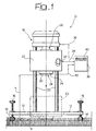
- the reference number 10 indicates, as a whole, an instrument (or “artificial athlete") that can be used for implementation of the solution described herein.
- the instrument 10 basically comprises:
- the upright 18 has one or, preferably, a plurality of vertical rods 20, along which there can slide vertically in conditions of low friction a slide 22 carrying a weight 24.
- the slide 22 (and hence the weight 24 carried thereby) is designed to be withheld in a raised position by an electromagnet 26 set in the top part of the upright 18.
- the position of retention of the slide 22 by the electromagnet 26 can be selectively adjusted so as to cause the bottom surface of the weight 24 to be at a height h adjusted precisely (for example, within plus or minus five tenths of a millimetre) with respect to the surface S of which it is desired to determine - according to the modalities described in greater detail in what follows - the biomechanical characteristics of tread.
- the surface S is made up of grass cover (either natural or synthetic).
- the distance h (equal, for example, to 1250 tenths of a millimetre) will then be assumed as determined basically with respect to the surface of the ground from which there emerge the blades of grass.
- adjustment of the height h is made preferably by causing the feet 14 to rest on a plate (template) made of rigid material, for example metal, laid on the ground.
- a plate made of rigid material, for example metal, laid on the ground.
- the height h is in general referred to the top level of the infill dispersed between the filiform formations that simulate the sward or turf for the purpose of keeping them in the upright position.
- the value of 1250 tenths of a millimetre indicated above for the height h is to be understood purely for the purpose of providing an example. Similar considerations apply as regards the choice of the weight of the body 24. For example, the tests so far conducted by the present applicant have been carried out with a body having a weight in the region of 11.5 kg. Comprised in said value is also the weight of the slide 22.
- At least the top part of the ensemble represented by the slide 22 and the weight 24 (and preferably the entire ensemble) is made of ferromagnetic material.
- the electromagnet 26 is designed to withhold the weight 24 initially in the raised position represented by the solid line in Figure 1.
- the weight 24 is released and falls rapidly (in a way that may substantially be viewed as a sort of free fall), starting from the height h and hits, with a front face or surface of impact 28 (i.e., the bottom surface in the condition of normal use of the instrument 10 represented in Figure 1), the surface S that is to be characterized.
- the impact has the characteristics of an at least partially elastic impact and hence leads to a phenomenon of return or bouncing back up of the weight 24.
- the front arrangement of assembly of the dynamometric sensor 30 is not imperative.
- the sensor 30 can be mounted also in quite a remote position with respect to the front face 28, albeit retaining the possibility of detecting the intensity of the force applied against said front face during the phenomenon of falling (and bouncing back) of the weight 24 on the surface S.
- the aforesaid front face bears a spring associated to which is a deformation sensor
- the aforesaid front surface is - substantially - rigid.
- the connotation of the front face 28 of the weight 24 as a "substantially rigid" surface has the purpose of taking into account the fact that the dynamometric sensor 30 is made up usually of deformation gauges.
- the deformation gauges' in question detect the force applied thereto according to the deformation imposed by said force, in particular in the form of a percentage variation in length.
- the deformation gauges detect the force applied thereto according to the deformation imposed by said force, in particular in the form of a percentage variation in length.
- deformations intrinsically linked to the operation of a deformation gauge of said nature are micrometric deformations and, as such, they do not derogate from the characteristic of substantial rigidity of the face of impact 28 of the weight 24: this applies to a particularly evident extent in the case where the dynamometric sensor 30 is mounted in a remote position with respect to the face 28.
- Associated to the slide 22 are one or more linear-position transducers, which are designed to detect the position reached by the slide 22 (and hence by the weight 24 carried thereby) on the guides 20 of the upright 18.
- the transducer or the transducers 32 are hence able to detect, with high precision, the distance that separates the front face or surface of impact 28 of the weight 24 from the surface S to be characterized.
- the transducers 32 can advantageously consist of contactless linear-position transducers, of the magnetostrictive type.
- the absence of electrical contact on the slider eliminates, in transducers of this type, the problems of wear and tear, guaranteeing a practically unlimited duration, at the same time ensuring that the movement of sliding (falling) of the weight 24 along the guides 20 may occur in conditions that may substantially be likened to the conditions of free fall.
- Sensors 32 of the type specified above which present a high performance in terms of linearity, repeatability, resistance to vibrations and to mechanical shocks, are commonly available on the market, and are produced by the firm Gefran S.p.A. of Provaglio d'Iseo (Brescia) - Italy.
- the magnetostrictive transducers in question are able to supply, on a respective output line 34, an analog signal directly as a voltage and/or a current, without requiring any electronic treatment of the signal whenever they are interfaced with devices such as a controller or measuring instruments.
- the reference number 36 designates a control and processing unit that is advantageously configurable in the form of a personal computer, possibly associated to the device 10 with the provision of an interface (of a known type) for gathering and processing of the measurement data.
- the unit 36 controls, via a line 38, the electromagnet 26 (and is thus able to control falling of the weight 24 selectively). It likewise receives, on a line 40, the signal of the dynamometric sensor 30 and hence receives at input a signal representing the force exerted on the front face or surface of impact 28 of the weight 24.
- the step 100 indicates an initial step, in which the instrument 10 is "set” by bringing the slide 22 into a raised position and activating the electromagnet 26 so that the slide 22 and the weight 24 carried thereby are maintained in a raised position, with the front face 28 of the weight 24 located at the distance h (precisely adjustable, for example by operating on the feet 14) from the surface S that is to be characterized.
- control unit 36 controls deactivation of the electromagnet 26, causing the weight 24 to fall vertically along the upright 18 so as to reach gradually the position designated by the dashed line in Figure 1.
- the unit 36 records, with a set of operations, represented, as a whole, by step 104, the trend of the output signal of the position sensor or sensors 32 and of the dynamometric sensor 30.
- the operation of detection in question entails sampling of the output signal of the position sensor or sensors 32 and of the dynamometric sensor 30 at a frequency of approximately 20 kHz.
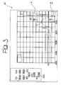
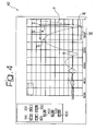
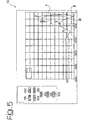
- the unit 36 is able to gather and store signals basically corresponding to the diagrams indicated, respectively, by the curves A and B in the graphs of Figures 3, 4 and 5.
- the scale of the abscissa is a time scale with orientation from right to left.
- the point designated by 0 on the right
- the time scale measured in milliseconds, represents the time of evolution of the phenomena represented by the curves A and B.
- the curve A represents, instant by instant, the vertical position of the front face 28 of the weight 24, measured with respect to the plane of lie of the surface S.
- the corresponding value of height is equal to the value h.
- the value of said height decreases rapidly as a result of the vertical falling of the weight 24 along the guides 20.
- the surface S "restores" the deformation energy, displacing once again upwards the weight 24, which returns/bounces back up until it reaches a maximum distance of return/bouncing with respect to the surface S, and then drops back down, penetrating again into the surface S (negative values of the scale of the ordinate of the diagrams of Figures 3 to 5) and thus giving rise to new phenomena of bouncing (particularly evident in the curve A of Figure 4), which are then gradually damped.
- the weight 24 usually comes to rest on the surface S in a position in which the front surface 28 is at least slightly below the original level of the surface S; this fact is altogether understandable, since, in the presence of a compliant surface S, the weight 24 tends to form a sort of more or less hollow impression in the surface S.
- the curve B of the diagrams corresponds to the output signal of the dynamometric sensor 30 and hence has a pattern co-ordinated with respect to the pattern of the diagram A.
- the force signal B basically presents peaks in the regions of maximum deformation of the surface S and in the immediately subsequent steps, in which the surface (i.e., more correctly, the flooring delimited superficially by said surface) restores the deformation energy accumulated, sending the weight 24 back upwards.
- the curve B has (in all three of the diagrams of Figures 3 to 5) a first very marked peak corresponding to the first phenomenon of return/bouncing and subsequent increasingly less important peaks.
- the steps 106 to 112 of the flowchart of Figure 2 identify subsequent steps of processing, conducted by the unit 36 (or by the processing module such as a personal computer, to which the latter is connected) on the output signals of the sensors 32 and 30.
- the unit 36 detects the maximum value, designated by I (and normally expressed in kgf), of the force exerted by the weight 24 on the surface S and hence, as evident effect of reaction, by the surface S on the weight 24. This is hence the initial value (maximum) of the force with which the surface S restores to the weight 24 the deformation energy accumulated as a result of the impact of the weight 24 on the surface S.
- This value is usually presented on a display screen 42 associated to the unit 36, in particular in a display field designated by 200 (see Figures 3 to 5).
- the parameter indicated is a biomechanical parameter not envisaged by any standard currently in force at the moment of filing of the present application and is considered as representing the "return" that an athlete who walks or runs on the surface S experiences, following upon each individual impact.
- the unit 36 identifies the value of the first minimum, designated by II, of the curve designated by A.
- This value of deformation is indicative of the maximum actual deformation of the surface S consequent on impact, measured for example in tenths of a millimetre. It is hence the value of initial deformation, starting from which the surface S restores to the weight 24 the deformation energy accumulated as a result of the impact of the weight 24 on the surface S. It is also in this case a parameter of a biomechanical type, not envisaged by any standard currently in force at the moment of filing of the present application.
- the unit 36 determines the duration of the time interval (designated by III) between the point in which the maximum deformation is reached (point referred to previously and designated by II) and the maximum value, which follows immediately thereon, of the curve A, i.e., the moment in which there is the maximum value of height of return or bouncing of the weight 24 upwards with respect to the surface S.
- the time of return III measured usually in thousandths of a second, is basically indicative of the duration of the process with which the surface S restores to the weight 24 the deformation energy accumulated as a result of the impact of the weight 24 on the surface S.
- the time of return III is displayed in a field 400 of the display unit 42. Also in this case it is a biomechanical parameter, not envisaged by any standard currently in force at the moment of filing of the present application, which is proportional to the time of reactivity of the surface S.
- the unit 36 then detects a value of return time corresponding to the interval designated by IV in the diagrams of Figures 3 to 5.
- this parameter represents the process with which the surface S restores to the weight 24 the deformation energy accumulated as a result of the impact of the weight 24 on the surface S, but includes within i't also a measurement of the duration of the initial process of deformation.
- the parameter expressed in thousandths of a second, is not envisaged by any standard currently in force at the moment of filing of the present application. Also this is proportional to the time of reactivity of the ground.
- the unit 36 detects the ratio between the value of ordinates (designated by V) of the first maximum of the curve A and the height of falling of the weight 24, designated by h.
- this is a parameter representing the process whereby the surface S restores to the weight 24 the deformation energy accumulated as a result of the impact of the weight 24 on the surface S.
- this is a parameter of a biomechanical type not envisaged by any standard currently in force at the moment of the filing of the present application.
- the experiences conducted by the present applicant show that it is a particularly significant parameter.
- the parameter in question which is usually designed to be presented in a field 600 of the display unit 42 in the form of a percentage value, is proportional to the energy return that the athlete experiences following upon each individual impact.
- the kinetic energy is transferred to the surface S (or, more correctly, to the flooring of which the latter forms part) in the form of work absorbed and accumulated by the surface S as deformation energy.
- the surface S then restores to the weight 24 the deformation energy accumulated, sending it back upwards and transferring then to the weight 24 a kinetic energy which enables it to move again upwards with a movement of return/bouncing.
- the movement of return upwards involves a (re)transformation of the kinetic energy into potential energy, which reaches a new peak (maximum value) corresponding to the value of ordinate designated by V in the diagrams of Figures 3 to 5.
- the steps designated by 114 and 116 in the flowchart of Figure 2 finally indicate the fact that, together with the operations of detection and display described previously, it is possible to detect and display the values of KA and of standard deformation to which reference has been made in the introductory part of the present description. Said parameters can also be deduced from the signals supplied by the sensors with which the device/instrument 10 described herein is equipped, the purpose being to proceed to a display (exemplified by the step 118) of these additional parameters, in respective fields 700 and 800 of the display unit 42.
- the diagram of Figure 4 relates, instead, to an artificial synthetic flooring made up of synthetic grass filled in with granules of EPDM rubber and sand.
- curves A and B of Figure 4 (regarding a synthetic grass flooring/turf filled in with granules of rubber and sand) present an amply different pattern, characterized by an extremely high value of energy return.
- the parameter of energy return (yielded by step 112 and displayed in the field 600 of the display unit) will be particularly interesting and significant, in particular for those applications in which it is desired to achieve a synthetic grass flooring (turf) such as might reproduce in the most faithful way possible the characteristics of a given natural grass cover.
- natural grass cover can present, also in the case of pitches that are quite close to one another, biomechanical characteristics perceived as different by the athletes that use them. Between different pitches available in the same sports facility and/or in the same installation, the athletes can indicate a pitch that is particularly preferred by them.
Landscapes
- Chemical & Material Sciences (AREA)
- Health & Medical Sciences (AREA)
- Life Sciences & Earth Sciences (AREA)
- Immunology (AREA)
- Analytical Chemistry (AREA)
- Biochemistry (AREA)
- General Health & Medical Sciences (AREA)
- General Physics & Mathematics (AREA)
- Physics & Mathematics (AREA)
- Pathology (AREA)
- Engineering & Computer Science (AREA)
- Food Science & Technology (AREA)
- Medicinal Chemistry (AREA)
- Road Repair (AREA)
- Measurement Of The Respiration, Hearing Ability, Form, And Blood Characteristics Of Living Organisms (AREA)
- Investigating Strength Of Materials By Application Of Mechanical Stress (AREA)
- Escalators And Moving Walkways (AREA)
- Length Measuring Devices By Optical Means (AREA)
Claims (13)
- Verfahren zur Charakterisierung einer Kontakt-Oberfläche (S), wobei das Verfahren folgende Vorgänge umfasst:- Fallenlassen eines Gewichts (24) aus einer gegebenen Höhe (h) auf die Oberfläche (S), wobei die Umwandlung der Bewegungsenergie des Fallens des Gewichts (24) in Deformationsenergie der Oberfläche (S) erzeugt wird, wobei die Deformationsenergie in der Lage ist, durch die Oberfläche (S) in das Gewicht (24) zurückgespeichert zu werden, wobei das Gewicht (24) Gegenstand einer Bewegung aus Fallen und Abprallen ist; und- Erfassen von zumindest einem Parameter (I bis V), der den Vorgang der Rückspeicherung der Deformationsenergie durch die Oberfläche (S) in das Gewicht (24) verkörpert,dadurch gekennzeichnet,
dass das Verfahren folgende Schritte umfasst:- Abtasten (32, 30) der Position des Gewichts (24) und der gegen die Vorderseite (28) des Gewichts (24) ausgeübten Kraft während der Bewegung aus Fallen und Abprallen, und- Aufzeichnen der Tendenzen von Signalen, die für die Position und die Kraft repräsentativ sind; wobei die beiden Tendenzen zur Identifizierung der Kontakteigenschaften der Oberfläche (S) verwendet werden. - Verfahren nach Anspruch 1, dadurch gekennzeichnet, dass der zumindest eine Parameter aus der folgenden Gruppe ausgewählt wird:- der Wert (I) der zu Beginn des Vorgangs der Rückübertragung der Deformationsenergie durch die Oberfläche (S) in das Gewicht (24) durch die Oberfläche (S) ausgeübten Reaktionskraft;- der Wert der Deformation (II) der Oberfläche (S) zu Beginn des Vorgangs der Rückspeicherung der Deformationsenergie durch die Oberfläche (S) in das Gewicht (24);- das Zeitintervall (III) zwischen dem Anfang des Vorgangs der Rückspeicherung der Deformationsenergie durch die Oberfläche (S) in das Gewicht (24) und der Moment, in dem das Gewicht (24) den maximalen Wert der aufwärtigen Rückkehr erreicht, die durch die Rückspeicherung der Deformationsenergie in das Gewicht (24) selbst durch die Oberfläche (S) bewirkt wird;- das Zeitintervall (IV) zwischen dem Moment, in dem das Gewicht (24) die Oberfläche (S) aufgrund des Fallens trifft und dem Moment, in dem das Gewicht (24) den maximalen Wert der aufwärtigen Rückkehr erreicht, die durch die Rückübertragung der Deformationsenergie in das Gewicht (24) selbst durch die Oberfläche (S) erzeugt wird; und- der Wert der Höhe (V), die durch das Gewicht (24) als Ergebnis der aufwärtigen Rückkehr erreicht wird, die durch die Rückübertragung der Deformationsenergie in das Gewicht (24) selbst durch die Oberfläche (S) erzeugt wird.
- Verfahren nach Anspruch 2, dadurch gekennzeichnet, dass es den Vorgang der Erfassung des Verhältnisses zwischen dem Wert der Höhe (V) der Rückkehr und der vorbestimmten Fallhöhe (h) des Gewichts (24) umfasst.
- Verfahren nach einem der vorhergehenden Ansprüche, dadurch gekennzeichnet, dass es den Vorgang der Anzeige (200, 300, 400, 500, 600) des zumindest einen erfassten Parameters umfasst.
- Verfahren nach einem der vorhergehenden Ansprüche, dadurch gekennzeichnet, dass die Oberfläche (S) eine Abdeckung oder ein Bodenbelag aus Gras ist.
- Verfahren nach Anspruch 5, dadurch gekennzeichnet, dass die Abdeckung oder der Bodenbelag aus Gras eine Abdeckung aus natürlichem Gras ist.
- Verfahren nach Anspruch 5, dadurch gekennzeichnet, dass die Abdeckung oder der Bodenbelag aus Gras eine synthetische Grasdecke (Rasendecke) ist.
- Verfahren zur Konstruktion von synthetischen Grasdecken, dadurch gekennzeichnet, dass es die folgenden Vorgänge umfasst:- Charakterisieren, unter Verwendung des Verfahrens nach einem der Ansprüche 1 bis 4, einer natürlichen Grasdecke durch Erfassen des zumindest einen Parameters (I bis V) bezüglich der natürlichen Grasdecke;- Erzeugen einer synthetischen Grasdecke oder Rasendecke;- Charakterisieren der synthetischen Grasdecke unter Verwendung des Verfahrens nach einem der Ansprüche 1 bis 5 durch homologes Erfassen des zumindest einen Parameters (I bis V) auf der synthetischen Grasdecke oder Rasendecke; und- Ausbilden der synthetischen Grasdecke oder Rasendecke ähnlich der natürlichen Grasdecke bezüglich des biomechanischen Standpunkts, wodurch sich der zumindest eine, homolog für die synthetische Grasdecke oder Rasendecke bestimmte Parameter (I bis V) an den zumindest einen, für die natürliche Grasdecke bestimmten Parameter (I bis V) annähert.
- Instrument zur Charakterisierung von Kontaktflächen (S), dadurch gekennzeichnet, dass es umfasst:- eine Struktur (12 bis 20), welche auf der zu charakterisierenden Oberfläche (S) positioniert werden kann;- ein durch die Struktur (12 bis 20) getragenes Gewicht (28) mit der Fähigkeit, ausgehend aus einer gegebenen Höhe (h) auf die Oberfläche (S) zu fallen, wobei das Gewicht (24) einer Bewegung des Fallens und Abprallens unterliegt, wobei das Gewicht (24) eine Vorderfläche (28) aufweist, die im Wesentlichen starr ist und in der Lage ist, die Oberfläche (S) als Ergebnis des Fallens des Gewichts (24) aus der vorbestimmten Höhe (h) zu treffen;- einen dynamometrischen Sensor (30), welcher in der Lage ist, die zwischen der Vorderfläche (28) des Gewichts (20) und der Oberfläche (S) übertragene Kraft zu detektieren, wobei ein entsprechendes Kraftsignal generiert wird; und- einen Positionssensor (32), welcher in der Lage ist, die von dem Gewicht (24) bezüglich der Struktur erreichte vertikale Position zu detektieren, wobei ein entsprechendes Positionssignal generiert wird,dadurch gekennzeichnet,
dass das Instrument eine Steuer- und Verarbeitungseinheit (36) zur Aufnahme der Tendenz des entsprechenden Kraftsignals und des entsprechenden Positionssignals während der Bewegung und des Abprallens umfasst, wobei die Kontakteigenschaften der Oberflächen (S) identifiziert werden. - Instrument nach Anspruch 9, dadurch gekennzeichnet, dass es umfasst:- ein Rückhalteelement (26) des Gewichts (24), das geeignet ist, das Gewicht (24) zu halten und es wählbar auf die Oberfläche (S) aus der gegebenen Höhe (h) fallen zu lassen, wodurch die Umwandlung der kinetischen Energie aus dem Fallen des Gewichts (24) in Deformationsenergie der Oberfläche (S) erzeugt wird, wobei die Deformationsenergie durch die Oberfläche (S) in das Gewicht (24) rückgespeichert werden kann; und- eine mit dem dynamometrischen Sensor (30) und dem Positionssensor (32) verbundene Verarbeitungseinheit (36), wobei die Verarbeitungseinheit dazu ausgelegt ist, ausgehend von den Kraft- und Positionssignalen zumindest einen Parameter (I bis V) zu bestimmen, der den Vorgang der Rückspeicherung der Deformationsenergie in dem Gewicht (24) durch die Oberfläche (S) repräsentiert, wobei der zumindest eine Parameter die Kontakteigenschaften der Oberfläche (S) identifiziert.
- Instrument nach Anspruch 10, dadurch gekennzeichnet, dass die Verarbeitungseinheit (36) zur Bestimmung von zumindest einem Parameter ausgebildet ist, der aus der Gruppe ausgewählt ist bestehend aus:- der Wert (I) der zu Beginn des Vorgangs der Rückübertragung der Deformationsenergie durch die Oberfläche (S) in das Gewicht (24) durch die Oberfläche (S) ausgeübten Reaktionskraft;- der Wert der Deformation (II) der Oberfläche (S) zu Beginn des Vorgangs der Rückspeicherung der Deformationsenergie durch die Oberfläche (S) in das Gewicht (24);- das Zeitintervall (III) zwischen dem Anfang des Vorgangs der Rückspeicherung der Deformationsenergie durch die Oberfläche (S) in das Gewicht (24) und der Moment, in dem das Gewicht (24) den maximalen Wert der aufwärtigen Rückkehr erreicht, die durch die Rückspeicherung der Deformationsenergie in das Gewicht (24) selbst durch die Oberfläche (S) bewirkt wird;- das Zeitintervall (IV) zwischen dem Moment, in dem das Gewicht (24) die Oberfläche (S) aufgrund des Fallens trifft und dem Moment, in dem das Gewicht (24) den maximalen Wert der aufwärtigen Rückkehr erreicht, die durch die Rückübertragung der Deformationsenergie in das Gewicht (24) selbst durch die Oberfläche (S) erzeugt wird; und- der Wert der Höhe (V), die durch das Gewicht (24) als Ergebnis der aufwärtigen Rückkehr erreicht wird, die durch die Rückübertragung der Deformationsenergie in das Gewicht (24) selbst durch die Oberfläche (S) erzeugt wird.
- Instrument nach Anspruch 10 oder Anspruch 11, dadurch gekennzeichnet, dass die Verarbeitungseinheit (36) dazu ausgelegt ist, das Verhältnis zwisehen dem Wert der Rückkehrhöhe (V) und der vorbestimmten Fallhöhe (h) des Gewichts (24) zu bestimmen.
- Instrument nach einem der vorhergehenden Ansprüche 9 bis 12, dadurch gekennzeichnet, dass es eine Anzeigeeinheit (42) zur Anzeige (200, 300, 400, 500, 600) des zumindest einen erfassten Parameters und der Tendenzen aufweist.
Priority Applications (10)
| Application Number | Priority Date | Filing Date | Title |
|---|---|---|---|
| PT04425022T PT1555522E (pt) | 2004-01-16 | 2004-01-16 | Processo e instrumento para caracterização da superfície de um piso, por exemplo, uma superfície de relva sintética |
| DK04425022T DK1555522T3 (da) | 2004-01-16 | 2004-01-16 | Fremgangsmåde og instrument til karakterisering af en overflade som skal betrædes, eksempelvis en syntetisk græsflade |
| AT04425022T ATE357650T1 (de) | 2004-01-16 | 2004-01-16 | Verfahren und gerät zur charakerisierung einer kontaktfläche, z. b. einer kunststoffrasenfläche |
| ES04425022T ES2285393T3 (es) | 2004-01-16 | 2004-01-16 | Procedimiento e instrumento para caracterizar una superficie de pisado, por ejemplo una superficie de cesped sintetico. |
| DE602004005410T DE602004005410T2 (de) | 2004-01-16 | 2004-01-16 | Verfahren und Gerät zur Charakerisierung einer Kontaktfläche, z. B. einer Kunststoffrasenfläche |
| EP04425022A EP1555522B1 (de) | 2004-01-16 | 2004-01-16 | Verfahren und Gerät zur Charakerisierung einer Kontaktfläche, z. B. einer Kunststoffrasenfläche |
| CA002481169A CA2481169A1 (en) | 2004-01-16 | 2004-09-13 | Method and instrument for characterizing treading surfaces, for instance for realizing synthetic turf surfaces |
| CN2004101026522A CN1641348B (zh) | 2004-01-16 | 2004-12-29 | 用于识别踩踏表面的特征以实现例如人造草皮表面的方法和装置 |
| US11/035,418 US7137285B2 (en) | 2004-01-16 | 2005-01-13 | Method and instrument for characterizing treading surfaces, for instance for realizing synthetic turf surfaces |
| JP2005007997A JP4694211B2 (ja) | 2004-01-16 | 2005-01-14 | 踏み付ける表面を特徴付ける、例えば人工芝生表面を理解するための方法及び器具 |
Applications Claiming Priority (1)
| Application Number | Priority Date | Filing Date | Title |
|---|---|---|---|
| EP04425022A EP1555522B1 (de) | 2004-01-16 | 2004-01-16 | Verfahren und Gerät zur Charakerisierung einer Kontaktfläche, z. B. einer Kunststoffrasenfläche |
Publications (2)
| Publication Number | Publication Date |
|---|---|
| EP1555522A1 EP1555522A1 (de) | 2005-07-20 |
| EP1555522B1 true EP1555522B1 (de) | 2007-03-21 |
Family
ID=34610260
Family Applications (1)
| Application Number | Title | Priority Date | Filing Date |
|---|---|---|---|
| EP04425022A Expired - Lifetime EP1555522B1 (de) | 2004-01-16 | 2004-01-16 | Verfahren und Gerät zur Charakerisierung einer Kontaktfläche, z. B. einer Kunststoffrasenfläche |
Country Status (10)
| Country | Link |
|---|---|
| US (1) | US7137285B2 (de) |
| EP (1) | EP1555522B1 (de) |
| JP (1) | JP4694211B2 (de) |
| CN (1) | CN1641348B (de) |
| AT (1) | ATE357650T1 (de) |
| CA (1) | CA2481169A1 (de) |
| DE (1) | DE602004005410T2 (de) |
| DK (1) | DK1555522T3 (de) |
| ES (1) | ES2285393T3 (de) |
| PT (1) | PT1555522E (de) |
Families Citing this family (22)
| Publication number | Priority date | Publication date | Assignee | Title |
|---|---|---|---|---|
| US7370538B2 (en) * | 2005-07-08 | 2008-05-13 | Certainteed Corporation | Method and apparatus for determining insulation thickness |
| EP1767921A1 (de) * | 2005-09-26 | 2007-03-28 | DSMIP Assets B.V. | Verfahren zur Bestimmung der Eignung eines Materials als Einstreumaterial in Kunstrasensystemen |
| US7617718B2 (en) | 2005-12-13 | 2009-11-17 | Sandy Golgart Sales, Inc. | Device and methods for use of a dynamic cone penetrometer for evaluating soil compaction |
| JP4622934B2 (ja) * | 2006-05-30 | 2011-02-02 | 住友金属工業株式会社 | 衝撃試験用落錘体 |
| US7591168B2 (en) * | 2007-02-02 | 2009-09-22 | Sony Ericsson Mobile Communications Ab | Test equipment system and method for testing a component |
| CN101059413B (zh) * | 2007-06-06 | 2010-05-19 | 宋立山 | 冲击吸收测试仪 |
| BRPI0816027B1 (pt) * | 2007-09-24 | 2019-05-28 | Dow Global Technologies Inc. | Superfície de gramado sintético |
| US20090235718A1 (en) * | 2008-03-21 | 2009-09-24 | Fox Michael J | Puncture-Resistant Containers and Testing Methods |
| IT1394937B1 (it) | 2009-01-12 | 2012-07-27 | Mondo Spa | Procedimento per realizzare materiale di riempimento per manti erbosi sintetici, corrispondente materiale e relativo manto erboso sintetico |
| ITRM20090226A1 (it) * | 2009-05-08 | 2009-08-07 | Federazione Italiana Bocce | Apparecchio per la misurazione del rimbalzo e della scorrevolezza delle corsie di gioco |
| AU2012201262B2 (en) * | 2011-03-01 | 2015-11-26 | The Toro Company | Evaluation of ground surface hardness |
| CN103558817A (zh) * | 2013-10-25 | 2014-02-05 | 桂林雅馨装饰工程有限公司 | 草坪绿化带管理系统 |
| CA2996477C (en) * | 2015-10-15 | 2022-09-06 | Simsage Pty Ltd | Apparatus and method for determining the hardness of a granular material |
| CN105424493B (zh) * | 2015-12-31 | 2018-02-27 | 国网冀北电力有限公司电力科学研究院 | 一种模拟绝缘子踩踏的试验装置 |
| CN106124154A (zh) * | 2016-08-26 | 2016-11-16 | 天津利福特电梯部件有限公司 | 电梯配重块抛摔试验机 |
| CN107219135B (zh) * | 2017-04-21 | 2020-06-26 | 江苏大学 | 一种振动筛分过程中蝇蛆恢复系数的测试方法 |
| CN106932194A (zh) * | 2017-04-27 | 2017-07-07 | 聊城鑫泰机床有限公司 | 一种机器人便携式能量回归检测机构 |
| EP3707990B1 (de) * | 2017-12-01 | 2021-07-14 | Sony Corporation | Informationsverarbeitungsvorrichtung, informationsverarbeitungsverfahren und vegetationsverwaltungssystem |
| RU2707907C1 (ru) * | 2019-04-29 | 2019-12-02 | Федеральное государственное бюджетное образовательное учреждение высшего образования "Чувашский государственный университет имени И.Н. Ульянова" | Полевой бесконтактный профилограф для спиралевидного сканирования |
| EP4100718A4 (de) * | 2020-03-04 | 2024-03-20 | Biocore LLC | Automatische rasenprüfvorrichtung und system zur verwendung desselben |
| US20250389630A1 (en) * | 2020-03-04 | 2025-12-25 | Biomechanics Consulting and Research, LLC | Automated surface testing device and system for using same |
| CN113494986A (zh) * | 2020-03-18 | 2021-10-12 | 富泰华工业(深圳)有限公司 | 跌落试验机 |
Family Cites Families (17)
| Publication number | Priority date | Publication date | Assignee | Title |
|---|---|---|---|---|
| FR2066356A5 (de) * | 1970-10-22 | 1971-08-06 | Bourdin Chausse Entre | |
| DE2311654B2 (de) * | 1973-03-09 | 1980-11-27 | Siegfried Herbert Moeckel, Gesellschaft Fuer Everplay Sportbelaege, Gmbh & Co Kg, 7912 Weissenhorn | Dreischichtiger, aus Kunststoffen bestehender Sporthallenbelag |
| GB1524445A (en) * | 1975-03-17 | 1978-09-13 | Univ Western Australia | Impact soil testing device |
| US4337283A (en) | 1980-09-11 | 1982-06-29 | Haas Jr Frederick T | Synthetic turf playing surface with resilient top-dressing |
| GB2206505B (en) | 1987-06-23 | 1992-01-29 | British Ind Sand Ltd | Surfacing composition |
| GB8802626D0 (en) * | 1988-02-05 | 1988-03-02 | Geotechnics Ltd | Impact testing apparatus |
| JPH06294724A (ja) * | 1993-04-09 | 1994-10-21 | Hiroomi Miyagawa | 反発係数測定装置 |
| JPH0915129A (ja) * | 1995-06-29 | 1997-01-17 | Daido Steel Co Ltd | 反発係数測定方法および装置 |
| JPH09218145A (ja) * | 1996-02-08 | 1997-08-19 | Kureha Chem Ind Co Ltd | 競技場用測定装置 |
| US5976645A (en) | 1998-06-01 | 1999-11-02 | Safturf International Limited | Vertically draining, rubber-filled synthetic turf and method of manufacture |
| CA2247484C (en) | 1998-09-21 | 2001-07-24 | Jean Prevost | Process of laying synthetic grass |
| JP2000267736A (ja) * | 1999-03-17 | 2000-09-29 | Taro Shimosato | 能動的衝撃制御装置 |
| CN2399450Y (zh) * | 1999-12-06 | 2000-10-04 | 铁道建筑研究设计院 | 落锤式动态变形模量测试仪 |
| IT1320197B1 (it) | 2000-05-25 | 2003-11-26 | Mondo Spa | Struttura di manto erboso sintetico, relativo materiale particellareed impiego del materiale particellare stesso. |
| JP3491263B2 (ja) * | 2001-07-05 | 2004-01-26 | 株式会社セントラル技研 | 接触時間による地盤材料の変形特性の測定方法 |
| US6848293B2 (en) * | 2002-08-23 | 2005-02-01 | Johnson Controls Technology Company | Weight drop system |
| US6925858B2 (en) * | 2003-10-23 | 2005-08-09 | Testing Services, Inc. | Turf test apparatus |
-
2004
- 2004-01-16 ES ES04425022T patent/ES2285393T3/es not_active Expired - Lifetime
- 2004-01-16 AT AT04425022T patent/ATE357650T1/de not_active IP Right Cessation
- 2004-01-16 EP EP04425022A patent/EP1555522B1/de not_active Expired - Lifetime
- 2004-01-16 DE DE602004005410T patent/DE602004005410T2/de not_active Expired - Fee Related
- 2004-01-16 DK DK04425022T patent/DK1555522T3/da active
- 2004-01-16 PT PT04425022T patent/PT1555522E/pt unknown
- 2004-09-13 CA CA002481169A patent/CA2481169A1/en not_active Abandoned
- 2004-12-29 CN CN2004101026522A patent/CN1641348B/zh not_active Expired - Fee Related
-
2005
- 2005-01-13 US US11/035,418 patent/US7137285B2/en not_active Expired - Fee Related
- 2005-01-14 JP JP2005007997A patent/JP4694211B2/ja not_active Expired - Fee Related
Non-Patent Citations (1)
| Title |
|---|
| None * |
Also Published As
| Publication number | Publication date |
|---|---|
| CN1641348B (zh) | 2011-11-02 |
| DK1555522T3 (da) | 2007-07-30 |
| JP4694211B2 (ja) | 2011-06-08 |
| EP1555522A1 (de) | 2005-07-20 |
| DE602004005410T2 (de) | 2007-11-29 |
| JP2005201903A (ja) | 2005-07-28 |
| PT1555522E (pt) | 2007-06-25 |
| ATE357650T1 (de) | 2007-04-15 |
| US7137285B2 (en) | 2006-11-21 |
| CA2481169A1 (en) | 2005-07-16 |
| CN1641348A (zh) | 2005-07-20 |
| ES2285393T3 (es) | 2007-11-16 |
| DE602004005410D1 (de) | 2007-05-03 |
| US20050178184A1 (en) | 2005-08-18 |
Similar Documents
| Publication | Publication Date | Title |
|---|---|---|
| US7137285B2 (en) | Method and instrument for characterizing treading surfaces, for instance for realizing synthetic turf surfaces | |
| US5419565A (en) | Electrical device for detecting the location and speed or force of impact with a target | |
| US4088324A (en) | Athletic implement with visual range display | |
| US8752419B2 (en) | Compression measurement device | |
| JPH10118238A (ja) | 運動用具用装置およびフィードバック方法 | |
| US10814186B2 (en) | Portable tennis ball testing device | |
| US4840377A (en) | Electrical tape boundary sensor apparatus | |
| US20210164874A1 (en) | Rigidity Characteristics Measurement Device | |
| US6616556B1 (en) | Method and apparatus for measuring leg drive | |
| EP1857154A1 (de) | Schlägerbespannungs-Messgerät von Ballschlägern | |
| US20010009870A1 (en) | Captive ball golf practice tee with three-dimension velocity and two-axis spin measurement | |
| DE4426302A1 (de) | Schockkraftmesser für Kampfsportschlagtechniken | |
| US7329900B2 (en) | Bonding strength testing device | |
| US20210162284A1 (en) | Method for Measuring Rigidity Characteristics and System for Measuring Rigidity Characteristics | |
| RU2368411C1 (ru) | Способ определения динамических характеристик теннисной ракетки и мяча | |
| Carré et al. | An examination of the Clegg impact hammer test with regard to the playing performance of synthetic sports surfaces | |
| WO1991010480A1 (de) | Schlägerbespannungskontrollgerät | |
| JPH0587657A (ja) | 地盤支持力試験装置 | |
| CN218726244U (zh) | 一种垂直弹性试验机 | |
| AU2007237288A1 (en) | Impact severity gauge | |
| CN121855905A (zh) | 一种蹦床检测装置 | |
| CN224007900U (zh) | 一种鞋头耐冲击防护性能测试装置 | |
| CN2852104Y (zh) | 一维冲击强度测试装置 | |
| CN222809977U (zh) | 一种高速公路压实度检测装置 | |
| CN220110381U (zh) | 一种可调节排球定点扣球发球训练装置 |
Legal Events
| Date | Code | Title | Description |
|---|---|---|---|
| PUAI | Public reference made under article 153(3) epc to a published international application that has entered the european phase |
Free format text: ORIGINAL CODE: 0009012 |
|
| AK | Designated contracting states |
Kind code of ref document: A1 Designated state(s): AT BE BG CH CY CZ DE DK EE ES FI FR GB GR HU IE IT LI LU MC NL PT RO SE SI SK TR |
|
| AX | Request for extension of the european patent |
Extension state: AL LT LV MK |
|
| RAP1 | Party data changed (applicant data changed or rights of an application transferred) |
Owner name: MONDO S.P.A. |
|
| 17P | Request for examination filed |
Effective date: 20051130 |
|
| AKX | Designation fees paid |
Designated state(s): AT BE BG CH CY CZ DE DK EE ES FI FR GB GR HU IE IT LI LU MC NL PT RO SE SI SK TR |
|
| GRAP | Despatch of communication of intention to grant a patent |
Free format text: ORIGINAL CODE: EPIDOSNIGR1 |
|
| GRAS | Grant fee paid |
Free format text: ORIGINAL CODE: EPIDOSNIGR3 |
|
| GRAA | (expected) grant |
Free format text: ORIGINAL CODE: 0009210 |
|
| AK | Designated contracting states |
Kind code of ref document: B1 Designated state(s): AT BE BG CH CY CZ DE DK EE ES FI FR GB GR HU IE IT LI LU MC NL PT RO SE SI SK TR |
|
| PG25 | Lapsed in a contracting state [announced via postgrant information from national office to epo] |
Ref country code: SI Free format text: LAPSE BECAUSE OF FAILURE TO SUBMIT A TRANSLATION OF THE DESCRIPTION OR TO PAY THE FEE WITHIN THE PRESCRIBED TIME-LIMIT Effective date: 20070321 |
|
| REG | Reference to a national code |
Ref country code: GB Ref legal event code: FG4D |
|
| REG | Reference to a national code |
Ref country code: CH Ref legal event code: EP |
|
| REF | Corresponds to: |
Ref document number: 602004005410 Country of ref document: DE Date of ref document: 20070503 Kind code of ref document: P |
|
| REG | Reference to a national code |
Ref country code: IE Ref legal event code: FG4D |
|
| REG | Reference to a national code |
Ref country code: SE Ref legal event code: TRGR |
|
| REG | Reference to a national code |
Ref country code: PT Ref legal event code: SC4A Free format text: AVAILABILITY OF NATIONAL TRANSLATION Effective date: 20070614 |
|
| REG | Reference to a national code |
Ref country code: CH Ref legal event code: NV Representative=s name: ISLER & PEDRAZZINI AG |
|
| REG | Reference to a national code |
Ref country code: GR Ref legal event code: EP Ref document number: 20070401743 Country of ref document: GR |
|
| REG | Reference to a national code |
Ref country code: DK Ref legal event code: T3 |
|
| ET | Fr: translation filed | ||
| REG | Reference to a national code |
Ref country code: CH Ref legal event code: PCAR Free format text: ISLER & PEDRAZZINI AG;POSTFACH 1772;8027 ZUERICH (CH) |
|
| REG | Reference to a national code |
Ref country code: ES Ref legal event code: FG2A Ref document number: 2285393 Country of ref document: ES Kind code of ref document: T3 |
|
| PG25 | Lapsed in a contracting state [announced via postgrant information from national office to epo] |
Ref country code: SK Free format text: LAPSE BECAUSE OF FAILURE TO SUBMIT A TRANSLATION OF THE DESCRIPTION OR TO PAY THE FEE WITHIN THE PRESCRIBED TIME-LIMIT Effective date: 20070321 |
|
| PG25 | Lapsed in a contracting state [announced via postgrant information from national office to epo] |
Ref country code: RO Free format text: LAPSE BECAUSE OF FAILURE TO SUBMIT A TRANSLATION OF THE DESCRIPTION OR TO PAY THE FEE WITHIN THE PRESCRIBED TIME-LIMIT Effective date: 20070321 Ref country code: CZ Free format text: LAPSE BECAUSE OF FAILURE TO SUBMIT A TRANSLATION OF THE DESCRIPTION OR TO PAY THE FEE WITHIN THE PRESCRIBED TIME-LIMIT Effective date: 20070321 |
|
| PLBE | No opposition filed within time limit |
Free format text: ORIGINAL CODE: 0009261 |
|
| STAA | Information on the status of an ep patent application or granted ep patent |
Free format text: STATUS: NO OPPOSITION FILED WITHIN TIME LIMIT |
|
| 26N | No opposition filed |
Effective date: 20071227 |
|
| PG25 | Lapsed in a contracting state [announced via postgrant information from national office to epo] |
Ref country code: EE Free format text: LAPSE BECAUSE OF FAILURE TO SUBMIT A TRANSLATION OF THE DESCRIPTION OR TO PAY THE FEE WITHIN THE PRESCRIBED TIME-LIMIT Effective date: 20070321 |
|
| PGFP | Annual fee paid to national office [announced via postgrant information from national office to epo] |
Ref country code: AT Payment date: 20090113 Year of fee payment: 6 Ref country code: DK Payment date: 20090113 Year of fee payment: 6 Ref country code: ES Payment date: 20090218 Year of fee payment: 6 Ref country code: IE Payment date: 20090115 Year of fee payment: 6 Ref country code: LU Payment date: 20090129 Year of fee payment: 6 |
|
| PGFP | Annual fee paid to national office [announced via postgrant information from national office to epo] |
Ref country code: DE Payment date: 20090115 Year of fee payment: 6 Ref country code: FI Payment date: 20090114 Year of fee payment: 6 Ref country code: NL Payment date: 20090125 Year of fee payment: 6 Ref country code: PT Payment date: 20090112 Year of fee payment: 6 |
|
| PGFP | Annual fee paid to national office [announced via postgrant information from national office to epo] |
Ref country code: CH Payment date: 20090114 Year of fee payment: 6 Ref country code: GB Payment date: 20090114 Year of fee payment: 6 Ref country code: GR Payment date: 20090123 Year of fee payment: 6 |
|
| PG25 | Lapsed in a contracting state [announced via postgrant information from national office to epo] |
Ref country code: CY Free format text: LAPSE BECAUSE OF FAILURE TO SUBMIT A TRANSLATION OF THE DESCRIPTION OR TO PAY THE FEE WITHIN THE PRESCRIBED TIME-LIMIT Effective date: 20070321 |
|
| PGFP | Annual fee paid to national office [announced via postgrant information from national office to epo] |
Ref country code: BE Payment date: 20090216 Year of fee payment: 6 |
|
| PG25 | Lapsed in a contracting state [announced via postgrant information from national office to epo] |
Ref country code: BG Free format text: LAPSE BECAUSE OF FAILURE TO SUBMIT A TRANSLATION OF THE DESCRIPTION OR TO PAY THE FEE WITHIN THE PRESCRIBED TIME-LIMIT Effective date: 20070621 |
|
| PGFP | Annual fee paid to national office [announced via postgrant information from national office to epo] |
Ref country code: SE Payment date: 20090128 Year of fee payment: 6 Ref country code: TR Payment date: 20090114 Year of fee payment: 6 |
|
| PGFP | Annual fee paid to national office [announced via postgrant information from national office to epo] |
Ref country code: MC Payment date: 20090128 Year of fee payment: 6 |
|
| PGFP | Annual fee paid to national office [announced via postgrant information from national office to epo] |
Ref country code: FR Payment date: 20090129 Year of fee payment: 6 |
|
| REG | Reference to a national code |
Ref country code: PT Ref legal event code: MM4A Free format text: LAPSE DUE TO NON-PAYMENT OF FEES Effective date: 20100716 |
|
| PG25 | Lapsed in a contracting state [announced via postgrant information from national office to epo] |
Ref country code: HU Free format text: LAPSE BECAUSE OF FAILURE TO SUBMIT A TRANSLATION OF THE DESCRIPTION OR TO PAY THE FEE WITHIN THE PRESCRIBED TIME-LIMIT Effective date: 20070922 |
|
| BERE | Be: lapsed |
Owner name: MONDO S.P.A. Effective date: 20100131 |
|
| REG | Reference to a national code |
Ref country code: NL Ref legal event code: V1 Effective date: 20100801 |
|
| PG25 | Lapsed in a contracting state [announced via postgrant information from national office to epo] |
Ref country code: MC Free format text: LAPSE BECAUSE OF NON-PAYMENT OF DUE FEES Effective date: 20100131 |
|
| REG | Reference to a national code |
Ref country code: CH Ref legal event code: PL |
|
| REG | Reference to a national code |
Ref country code: DK Ref legal event code: EBP |
|
| GBPC | Gb: european patent ceased through non-payment of renewal fee |
Effective date: 20100116 |
|
| EUG | Se: european patent has lapsed | ||
| REG | Reference to a national code |
Ref country code: FR Ref legal event code: ST Effective date: 20100930 |
|
| PG25 | Lapsed in a contracting state [announced via postgrant information from national office to epo] |
Ref country code: LI Free format text: LAPSE BECAUSE OF NON-PAYMENT OF DUE FEES Effective date: 20100131 Ref country code: FR Free format text: LAPSE BECAUSE OF NON-PAYMENT OF DUE FEES Effective date: 20100201 Ref country code: NL Free format text: LAPSE BECAUSE OF NON-PAYMENT OF DUE FEES Effective date: 20100801 Ref country code: CH Free format text: LAPSE BECAUSE OF NON-PAYMENT OF DUE FEES Effective date: 20100131 |
|
| PG25 | Lapsed in a contracting state [announced via postgrant information from national office to epo] |
Ref country code: FI Free format text: LAPSE BECAUSE OF NON-PAYMENT OF DUE FEES Effective date: 20100116 Ref country code: DE Free format text: LAPSE BECAUSE OF NON-PAYMENT OF DUE FEES Effective date: 20100803 Ref country code: AT Free format text: LAPSE BECAUSE OF NON-PAYMENT OF DUE FEES Effective date: 20100116 |
|
| PG25 | Lapsed in a contracting state [announced via postgrant information from national office to epo] |
Ref country code: GB Free format text: LAPSE BECAUSE OF NON-PAYMENT OF DUE FEES Effective date: 20100116 |
|
| PG25 | Lapsed in a contracting state [announced via postgrant information from national office to epo] |
Ref country code: IE Free format text: LAPSE BECAUSE OF NON-PAYMENT OF DUE FEES Effective date: 20100118 Ref country code: PT Free format text: LAPSE BECAUSE OF NON-PAYMENT OF DUE FEES Effective date: 20100716 Ref country code: DK Free format text: LAPSE BECAUSE OF NON-PAYMENT OF DUE FEES Effective date: 20100131 |
|
| PG25 | Lapsed in a contracting state [announced via postgrant information from national office to epo] |
Ref country code: BE Free format text: LAPSE BECAUSE OF NON-PAYMENT OF DUE FEES Effective date: 20100131 |
|
| REG | Reference to a national code |
Ref country code: ES Ref legal event code: FD2A Effective date: 20110328 |
|
| PG25 | Lapsed in a contracting state [announced via postgrant information from national office to epo] |
Ref country code: ES Free format text: LAPSE BECAUSE OF NON-PAYMENT OF DUE FEES Effective date: 20110315 |
|
| PG25 | Lapsed in a contracting state [announced via postgrant information from national office to epo] |
Ref country code: ES Free format text: LAPSE BECAUSE OF NON-PAYMENT OF DUE FEES Effective date: 20100117 |
|
| PGFP | Annual fee paid to national office [announced via postgrant information from national office to epo] |
Ref country code: IT Payment date: 20120109 Year of fee payment: 9 |
|
| PG25 | Lapsed in a contracting state [announced via postgrant information from national office to epo] |
Ref country code: LU Free format text: LAPSE BECAUSE OF NON-PAYMENT OF DUE FEES Effective date: 20100116 Ref country code: SE Free format text: LAPSE BECAUSE OF NON-PAYMENT OF DUE FEES Effective date: 20100117 |
|
| PG25 | Lapsed in a contracting state [announced via postgrant information from national office to epo] |
Ref country code: TR Free format text: LAPSE BECAUSE OF NON-PAYMENT OF DUE FEES Effective date: 20100116 |
|
| PG25 | Lapsed in a contracting state [announced via postgrant information from national office to epo] |
Ref country code: IT Free format text: LAPSE BECAUSE OF NON-PAYMENT OF DUE FEES Effective date: 20130116 |