EP1555514A1 - Messfühler, Verfahren zu dessen Herstellung und elektrisches Gerät mit dem Messfühler - Google Patents
Messfühler, Verfahren zu dessen Herstellung und elektrisches Gerät mit dem Messfühler Download PDFInfo
- Publication number
- EP1555514A1 EP1555514A1 EP04030325A EP04030325A EP1555514A1 EP 1555514 A1 EP1555514 A1 EP 1555514A1 EP 04030325 A EP04030325 A EP 04030325A EP 04030325 A EP04030325 A EP 04030325A EP 1555514 A1 EP1555514 A1 EP 1555514A1
- Authority
- EP
- European Patent Office
- Prior art keywords
- sensor
- sleeve
- contact
- mass
- constriction
- Prior art date
- Legal status (The legal status is an assumption and is not a legal conclusion. Google has not performed a legal analysis and makes no representation as to the accuracy of the status listed.)
- Granted
Links
- 238000000034 method Methods 0.000 title claims abstract description 11
- 238000004519 manufacturing process Methods 0.000 title claims abstract description 8
- 239000000523 sample Substances 0.000 claims abstract description 23
- 239000013013 elastic material Substances 0.000 claims description 17
- 238000000576 coating method Methods 0.000 claims description 15
- 239000011248 coating agent Substances 0.000 claims description 14
- 150000001875 compounds Chemical class 0.000 claims description 8
- 238000004382 potting Methods 0.000 claims description 8
- 238000005452 bending Methods 0.000 claims description 7
- 230000007704 transition Effects 0.000 claims description 3
- 238000009529 body temperature measurement Methods 0.000 claims 1
- 230000004044 response Effects 0.000 abstract description 12
- 230000008901 benefit Effects 0.000 abstract description 11
- 239000000463 material Substances 0.000 description 12
- 238000003780 insertion Methods 0.000 description 9
- 230000037431 insertion Effects 0.000 description 9
- 241000209035 Ilex Species 0.000 description 4
- 230000009286 beneficial effect Effects 0.000 description 3
- 238000013461 design Methods 0.000 description 3
- 230000008569 process Effects 0.000 description 3
- 239000010935 stainless steel Substances 0.000 description 3
- 229910001220 stainless steel Inorganic materials 0.000 description 3
- 230000000930 thermomechanical effect Effects 0.000 description 3
- 238000005406 washing Methods 0.000 description 3
- RYGMFSIKBFXOCR-UHFFFAOYSA-N Copper Chemical compound [Cu] RYGMFSIKBFXOCR-UHFFFAOYSA-N 0.000 description 2
- XEEYBQQBJWHFJM-UHFFFAOYSA-N Iron Chemical compound [Fe] XEEYBQQBJWHFJM-UHFFFAOYSA-N 0.000 description 2
- PXHVJJICTQNCMI-UHFFFAOYSA-N Nickel Chemical compound [Ni] PXHVJJICTQNCMI-UHFFFAOYSA-N 0.000 description 2
- 230000015556 catabolic process Effects 0.000 description 2
- 238000006731 degradation reaction Methods 0.000 description 2
- 239000000945 filler Substances 0.000 description 2
- 238000007373 indentation Methods 0.000 description 2
- 238000009434 installation Methods 0.000 description 2
- 239000011344 liquid material Substances 0.000 description 2
- 238000012986 modification Methods 0.000 description 2
- 230000004048 modification Effects 0.000 description 2
- 229920001296 polysiloxane Polymers 0.000 description 2
- 238000012546 transfer Methods 0.000 description 2
- 240000003517 Elaeocarpus dentatus Species 0.000 description 1
- 229910045601 alloy Inorganic materials 0.000 description 1
- 239000000956 alloy Substances 0.000 description 1
- 230000015572 biosynthetic process Effects 0.000 description 1
- 239000003518 caustics Substances 0.000 description 1
- 239000000919 ceramic Substances 0.000 description 1
- 238000010276 construction Methods 0.000 description 1
- 238000001816 cooling Methods 0.000 description 1
- 229910052802 copper Inorganic materials 0.000 description 1
- 239000010949 copper Substances 0.000 description 1
- 238000011161 development Methods 0.000 description 1
- 230000000694 effects Effects 0.000 description 1
- 238000005538 encapsulation Methods 0.000 description 1
- 239000003822 epoxy resin Substances 0.000 description 1
- 238000007654 immersion Methods 0.000 description 1
- 229910052742 iron Inorganic materials 0.000 description 1
- 239000007788 liquid Substances 0.000 description 1
- 230000007246 mechanism Effects 0.000 description 1
- 229910052759 nickel Inorganic materials 0.000 description 1
- TWNQGVIAIRXVLR-UHFFFAOYSA-N oxo(oxoalumanyloxy)alumane Chemical compound O=[Al]O[Al]=O TWNQGVIAIRXVLR-UHFFFAOYSA-N 0.000 description 1
- 239000002245 particle Substances 0.000 description 1
- 229920000647 polyepoxide Polymers 0.000 description 1
- 238000002360 preparation method Methods 0.000 description 1
- 230000003014 reinforcing effect Effects 0.000 description 1
- 239000000126 substance Substances 0.000 description 1
- 239000000725 suspension Substances 0.000 description 1
- 238000007740 vapor deposition Methods 0.000 description 1
Images
Classifications
-
- G—PHYSICS
- G01—MEASURING; TESTING
- G01K—MEASURING TEMPERATURE; MEASURING QUANTITY OF HEAT; THERMALLY-SENSITIVE ELEMENTS NOT OTHERWISE PROVIDED FOR
- G01K1/00—Details of thermometers not specially adapted for particular types of thermometer
- G01K1/16—Special arrangements for conducting heat from the object to the sensitive element
- G01K1/18—Special arrangements for conducting heat from the object to the sensitive element for reducing thermal inertia
Definitions
- the invention relates to a sensor for detecting physical sizes.
- Such a sensor is known for example from the DE 101 59 869 A1.
- a snap-in feeler described for insertion into the bore of a housing, wherein a sensor body and a sensor element by Contact elements are interconnected.
- the Sensor body with a cover bracket to protect the sensor Provided kinking.
- a sensor which comprises a sensor, which is arranged in a sleeve.
- the gap between the sensor and the sleeve is with a mass filled.
- a contact area between the sensor and the sleeve is free from the crowd.
- the sensor is advantageously for Detecting temperatures suitable.
- the probe specified here uses as a general The idea of the invention, by providing a Contact area between the sensor and the sleeve the Heat conduction from outside through the sleeve towards the sensor improve. This reduces the thermal response time for the Sensor.
- the embedding of the sensor in the mass is advantageous for fixing the individual system elements and order the mechanical strength, especially against Vibrations, improve.
- the sensor is not surrounded on all sides by the mass, but there is one mass-free area, with which the sensor with the sleeve in Contact stands. This is a mass-free area especially suitable for good heat conduction of on the outside, ie from the side of the sleeve into the sensor.
- material for the mass into which the sensor is embedded is often materials are used that bad are thermally conductive and the all - sided embedding of Sensors would have a high thermal response time.
- the sleeve In another embodiment of the sensor is in Contact area between the sleeve and the sensor arranged elastic material.
- the elastic material has the advantage that it is the degradation of thermo-mechanical stresses can serve between the sensor and the sleeve. Thermo-mechanical stresses can, for example result from a difference in thermal Expansion coefficients of the sleeve on the one hand and the sensor on the other hand.
- the elastic material may take the form of a coating of the Sensors are present.
- the sensor would have a outer shell, which consists of the elastic material.
- the sensor on all sides of such Be surrounded by a shell.
- the shell could for example by immersion in a corresponding be made liquid material.
- the elastic material also as a coating on the inside be provided of the sleeve.
- the elastic material to provide as a separate element between the sleeve and the sensor is arranged.
- the mass may be a Be potting compound. It can be used as potting the commonly used materials for such purposes Get used.
- the sleeve has a tubular section and a narrowing up. Under one tubular section is a section of the sleeve too understand that along a longitudinal center axis of the tubular section a consistent cross-sectional shape and area. In contrast, is under a narrowing a section of the sleeve to understand where the the Cross-sectional area along the longitudinal center axis of the sleeve in one way down.
- Shrinking the cross section does not necessarily have the entire length of Narrowing can be given, rather, the narrowing can also Have sections in which one opposite the tubular Section although reduced cross-section is present, this but over a certain section of the longitudinal center axis stays the same.
- the narrowing can also Include completion of the sleeve on one side of the sleeve. This means that the sleeve in the area of the narrowing as well closed is.
- the division of the sleeve into a relative to the constriction wide tubular section and a section that the Constriction has the advantage of being here described sensor easily by inserting a Elements suspended sensor made a sleeve can be, with a wide initial range when Inserting the positioning of the sensor facilitates and the subsequent tapered or narrowed area the sleeve making the contact area between the Sensor and the sleeve inner wall facilitates.
- the sleeve or the constriction of the sleeve can with be provided an inclined sleeve portion.
- the means that the constriction of the sleeve has side walls, which are inclined to the longitudinal center axis of the sleeve. At this Slanting sleeve walls, the sensor when inserting Slightly slide along the sleeve to later on his final position at the contact area.
- This embodiment of the sleeve has the advantage that when sliding along the sensor at the Sleeve inner wall a hooking between the sleeve inner wall and the sensor can be prevented.
- the probe in another embodiment of the probe is a Plug provided, wherein the sensor by means of at least one Contact element is connected to the plug.
- the Contact elements are advantageously designed so that at lateral deflection of the sensor or the Contact elements a spring force is generated, the opposite the deflection acts.
- the number of contact elements can between 1, 2 and also an even larger number of vary such elements.
- the number is the contact elements two, namely one element for the two electrical poles of a voltage supply of the sensor.
- This embodiment of the probe has the advantage that when pushing the sensor and the sleeve through Along the sliding of the sensor on the sleeve inner wall a Spring force can be built up, which the sensor against the Sleeve inner wall presses and thus for a safe Design of the contact area ensures.
- a Sleeve provided, which is eccentric to a longitudinal central axis the sleeve is designed.
- Such an eccentric sleeve can be used a centrically arranged per se or centric designed element containing a plug, electrical Connecting elements or contact elements and the Sensor by sliding the eccentric sleeve so too configure the sensor on the eccentric part of the Sleeve inner wall rests and thus the desired Contact area forms.
- the plug in a subsequent step still can be connected to the sleeve to one to achieve a mechanically stable, compact construction.
- the procedure given here is the basic idea use, after which by the last end funnel-shaped Design, so the tapering down Design of the sleeve a simple insertion of the sensor in can achieve the sleeve.
- the sensor can be attached to the inner wall of the Slide along sleeve and is located at the end of the Insertion process, especially if the sensor during the insertion resiliently abuts the sleeve inner wall, automatically in a contact area with the sleeve, where a Immediate, ground-free contact with the Sleeve inner wall is guaranteed.
- the resilient Have properties there is the advantage that through the Along the sliding of the sensor on the oblique sleeve inner wall a permanent secure mechanical contact between the Sensor and the sleeve is guaranteed, from the beginning of first contact of the sensor with the sleeve inner wall to the End of the insertion process can exist and thus one secure contact area calls.
- a method for producing the Sensor particularly advantageous, wherein the contact elements are designed so that they move during the slippage of the Sensor on the inner wall by means of a spring force press against the inner wall.
- Viscosity of the mass in the sleeve is chosen so that the Sensor without significant bending of the contact elements by the mass can slide.
- Temperature sensor contains.
- the robust, protected by a sleeve sensor can be ensured that the sensor described here also under stressful outdoor conditions, for example in strong alkaline and therefore caustic suds easily over a long life can be used.
- the sensor For example, it can be used in washing machines or in tumble dryers as a temperature sensor function. By means of the sensor the temperature becomes measured and a temperature control device within the electrical device, preferably electrical Household appliance, controlled.
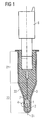
- Figure 1 shows a sensor in a first side view.
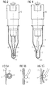
- FIG. 2 shows the sensor of FIG. 1 in a second, vertical side view.
- FIGS. 3A, 3B, 3C show different possibilities of Arrangement of an elastic material between the sensor and the sleeve.
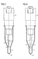
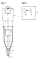
- FIGS. 4 to 7 show different possibilities of Arrangement of the electrical connection elements or the Sleeve.
- FIG. 8 shows an electrical device
- Figure 1 shows a sensor with a plug 6, to whose Bottom a sensor 1 is suspended.
- the suspension of the Sensor 1 is effected by means of a contact element 71.
- Die Bottom of the plug 6 and the contact element 71 and the Sensor 1 are covered by a sleeve 2.
- a gap between the sensor 1 and the sleeve 2 is filled with a Mass 3.
- the mass 3 fills the entire space in the Sleeve 2, not from other elements of the probe is filled.
- the sleeve 2 has a tubular portion 21 and a constricted section 22.
- the tubular portion 21 is located in the upper part of the sleeve 2.
- the narrowed Section 22 or the constriction 22 is located in the lower part of the sleeve 2.
- a contact area 4 wherein the Contact area 4 is characterized in that it is free from Mass is 3. In other words, at this point prevails a direct contact between the sleeve 2 and the sensor 1, but still an intermediate layer or a Material between sensor 1 and sleeve 2 may be provided.
- the contact element 71 extends in the upper region parallel and Centric to the longitudinal central axis 61 of the plug 6. In the bottom Area is the contact element 71 slightly to the left side bent, whereby the contact area 4 between the sensor. 1 and the sleeve 2 comes about.
- Figure 1 shows the sensor in the assembled state. In the unassembled state, so in a state where the sleeve 2 has not yet been pushed over the sensor 1, results in a slightly different picture.
- the deviation of the electrical contact element 71 to left side is still slightly larger than in Figure 1 shown.
- this mechanism presupposes that the Contact element 71 has resilient properties, that is, that it when exerting a lateral deflection of the sensor 1 thereto is suitable, one acting against the deflection To produce spring force.
- a contact element to a copper wire or the like use.
- the contact element Materials such as copper, iron, nickel and their alloys.
- the sensor 1 may advantageously be a wired NTC sensor ceramic act. Such sensors are advantageously used to, for example, in Range of household appliances to capture temperatures.
- the wired NTC sensor is contacted on the plug 6.
- the plug 6 has contact elements on its upper side, the insertion of the plug 6 in a device allows where a signal from the sensor 1 forwarded or is processed.
- the sleeve 1 is preferably made of stainless steel and has preferably a wall thickness of 0.2 to 1.0 mm.
- the formation of the sleeve 2 made of stainless steel has the advantage that they also in chemically aggressive environment, for example in Washing liquors still have sufficient chemical stability having. Accordingly, it is advantageous here to use described probe in places where he directly comes in contact with corrosive liquids. Furthermore Stainless steel has the advantage that it conducts the heat well and thus hardly limiting on the thermal response time of the Probe works.
- the mass 3 may advantageously be a potting compound with relatively simple means to process.
- an epoxy resin as a two-component system to use, where advantageously the viscosity in terms of the elements used, in particular in terms of the stiffness of the contact elements, the shape the sleeve is optimized to easily insert the Sensor 1 and the contact element 71 to allow without causing resistance or bending the sensor or the contact element 71 comes.
- Figure 1 is still apparent that the transition from tubular area 21 in the constricted area 22 without Corners, but executed with gentle curves, thus the insertion of the sensor 1 in the sleeve 2 facilitates is reduced, and the risk is that the sensor 1 at a corner gets stuck.
- the mass 3 after production of the probe is generally cured, which means that during installation of the probe in the sleeve 2 still existing spring force possibly in the finished state of the Probe can no longer be detected.
- Figure 2 shows the sensor of Figure 1 in another Side view, namely rotated by 90 °. It is here In particular, it can be seen that for fastening the sensor 1 on the plug 6 next to the contact element 71 yet another Contact element 72 is provided. To be as good as possible to achieve mechanical stability on the plug 6, are the contact elements 71, 72 in the vicinity of the plug 6 with arranged relatively large distance from each other. Toward the sensor 1 then narrows the distance of the Contact elements 71, 72.
- FIG. 3A shows an embodiment of the contact region 4 a sensor according to Figure 1, where in the contact area between the sensor 1 and the sleeve 2 an elastic material is arranged.
- This elastic material is in the form of a Coating 51 of the sensor 1 is provided.
- material comes for example, consider the use of silicone in Compound with fillers which, for example, particles can be made of aluminum oxide.
- the material silicone has the Advantage that it has a good elasticity, and therefore to Degradation of thermo-mechanical stresses between the sleeve. 2 and the sensor 1 is well suited.
- the introduction of the Filler has the advantage that the thermal conductivity of the elastic material can be improved, which is the reducing the thermal response time of the probe helps.
- the coating 51 of the sensor 1 can, for example be prepared by immersing the sensor 1 in a corresponding liquid material, which subsequently the Coating 51 forms.
- Figure 3B shows an embodiment according to Figure 3A, wherein however, the elastic material is not in the form of a Coating the sensor, but in the form of a coating 52 of the sleeve 2 is provided.
- the coating 52 of the sleeve 2 may, for example be prepared by immersing the sleeve 2 in a bath with appropriate material or by vapor deposition or similar coating methods.
- the material for the coating 52 is the same material considering how it is used for the coating 51.
- Figure 3C shows yet another example of the embodiment the elastic material between the sensor 1 and the sleeve 2, wherein the material in the form of a between the sensor 1 and the sleeve 2 laid, separate, independent part is realized.
- it is a separate element 53, which consists of elastic material.
- a Possibility is using a rotationally symmetrical sleeve an eccentric arrangement of To reach the sensor to ensure that the sensor with the sleeve forms a contact area.
- Another possibility is a centric one Arrangement of the sensor to combine with an eccentric shaped sleeve, which in turn can cause sleeve and Sensor form a contact area.
- a third possibility is to use the sleeve with a To provide a narrowing into which the sensor just fits, so that the sensor when pushing the sleeve in this Constriction can be pushed, and thus a sensor with surrounded on all sides or only on opposite sides Contact area can be realized.
- FIG. 4 shows a possible embodiment of the invention Sensor, wherein the sensor 1 with respect to the Longitudinal center axis 61, which for both the plug 1 and applies to the sleeve 2, is arranged eccentrically.
- FIG assembled state of the probe shows. I'm not yet assembled state, so without the pushed over Sleeve 2, the eccentricity of the sensor 1 is larger, the means the distance of the sensor 1 to the longitudinal center axis or in this case symmetry axis 61 is larger as shown in Figure 4.
- FIG. 1 Another possibility, the eccentricity of the sensor 1 to reach is shown in FIG.
- Contact elements 71, 72 are provided, both in the upper Area, so close to the connector 6 as well as in the lower area, so close to the sensor 1 parallel to each other.
- the Contact elements 71, 72 are also parallel to Longitudinal central axis 61. However, they are not centric to the longitudinal central axis 61, but they are eccentric and cause thereby also the eccentricity of the sensor 1.
- Eccentricity of the sensor 1 can be well predetermined, man note, however, that as already stated in FIG. 4, the Difference between the condition before and after assembly or after pushing the sleeve 2 on the Sensor 1 exists. It will ultimately be assumed that also in FIG. 5, where this is not explicitly shown, a slight bending of the contact elements 71, 72 for right side is present here to the desired Spring pressure in the direction of the inner wall of the sleeve 2 upright to obtain.
- FIG. 1 Another way to realize the eccentricity is shown in FIG.
- the contact elements 71, 72 extend here parallel to each other, but in comparison to Longitudinal axis 61 at an angle to this. Further are the contact elements 71, 72 are not centered on the plug 6, but inserted eccentrically, which for example by inclined sockets at the bottom of the plug. 6 can be achieved. Moreover, with respect to the Positions of the sensor 1 in the assembled and not assembled state the same as in Figure 4 and Figure 5 said.
- FIG. 7 shows a further possibility of the eccentricity of the To reach sensor 1.
- the Eccentricity is achieved by a corresponding Forming of the sleeve 2, which on the right side in the Compared to the left side receives enlarged indentation and where ultimately the contact area 4 through this indentation is produced.
- the Insertion of the sensor 1 in the sleeve 2 one not here shown bending of the contact elements 71, 72 generates is what produces the desired effect of the spring pressure, the Press the sensor 1 against the inner wall of the sleeve 2.
- Figure 8 shows schematically an electrical device 8, with a sensor 9 of the type described here is equipped. It Furthermore, by way of example, a heater 10 is provided which is controlled by the sensor 9.
- the electrical device 8 may preferably be a Home appliance, such as a washing machine or a Tumble act. Especially in this application area Low thermal response times are needed. About that In addition, this is also in this one Application area often present an aggressive environment, so that the probe must be suitably encapsulated, whereby only the competing demands for thermal Response time on the one hand and good encapsulation on the other are justified.
- the probe described here, the method for his Manufacture and the electrical device are not on the here illustrated and described embodiments limited. They also include all experts Modifications and partial and sub-combinations of described and illustrated features and measures. she also includes all modifications and partial and Subcombinations of the features shown in the figures and measures.
- the invention is not limited to sensors, which are suitable for detecting a temperature. she rather, includes all sensors that have a physical size capture and is beneficial wherever it is arrives at that sensor as possible with its surroundings same temperature is.
Landscapes
- Physics & Mathematics (AREA)
- General Physics & Mathematics (AREA)
- Measuring Temperature Or Quantity Of Heat (AREA)
Abstract
Description
- 1
- Sensor
- 2
- Hülse
- 21
- Rohrförmiger Abschnitt
- 22
- Verengter Abschnitt
- 3
- Masse
- 4
- Kontaktbereich
- 51
- Beschichtung des Sensors
- 52
- Beschichtung der Hülse
- 53
- Separates Element
- 6
- Stecker
- 61
- Mittellängsachse
- 71, 72
- Kontaktelement
- 8
- Elektrisches Gerät
- 9
- Fühler
- 10
- Heizung
Claims (17)
- Meßfühler enthaltendeinen Sensor (1), der in einer Hülse (2) angeordnet ist,wobei der Raum zwischen dem Sensor (1) und der Hülse (2) mit einer Masse (3) gefüllt ist,wobei ein Kontaktbereich (4) zwischen dem Sensor (1) und der Hülse (2) frei von der Masse (3) ist.
- Meßfühler nach Anspruch 1,
bei dem der Sensor (1) im Kontaktbereich (4) direkt an der Hülse (2) anstößt. - Meßfühler nach Anspruch 1,
bei dem im Kontaktbereich (4) zwischen der Hülse (2) und dem Sensor (1) elastisches Material angeordnet ist. - Meßfühler nach Anspruch 3,
bei dem das elastische Material in einer Beschichtung (51) des Sensors (1) enthalten ist. - Meßfühler nach Anspruch 3,
bei dem das elastische Material in einer Beschichtung (52) der Hülse (2) enthalten ist. - Meßfühler nach Anspruch 3,
bei dem das elastische Material in einem separaten Element (53) enthalten ist. - Meßfühler nach einem der Ansprüche 1 bis 6,
bei dem die Masse (3) eine Vergußmasse ist. - Meßfühler nach einem der Ansprüche 1 bis 7,
bei dem die Hülse (2) einen rohrförmigen Abschnitt (21) und eine Verengung (22) aufweist. - Meßfühler nach Anspruch 8,
bei dem sich der Kontaktbereich (4) im Bereich der Verengung (22) befindet. - Meßfühler nach einem der Ansprüche 8 oder 9,
bei dem die Verengung (22) mit einem schrägstehenden Abschnitt versehen ist. - Meßfühler nach einem der Ansprüche 8 bis 10,
bei dem der Übergang zwischen dem rohrförmigen Abschnitt (21) und der Verengung (22) frei von Kanten ausgeführt ist. - Meßfühler nach einem der Ansprüche 1 bis 11,
bei dem die Hülse (2) exzentrisch geformt ist. - Meßfühler nach einem der Ansprüche 1 bis 12,
bei dem ein Stecker (6) vorgesehen ist, wobei der Sensor (1) wenigstens mittels eines Kontaktelementes (71, 72) mit dem Stecker verbunden ist, wobei die Kontaktelemente (71, 72) bei seitlicher Auslenkung eine Federkraft entgegen der Auslenkung ausüben können. - Verfahren zur Herstellung eines Meßfühlers mit folgenden Schritten:a) Bereitstellen eines Steckers (6) mit einem Sensor (1), wobei der Sensor (1) mittels wenigstens eines Kontaktelements (71, 72) am Stecker (6) aufgehängt ist sowie Bereitstellen einer Hülse (2), die mit einer Masse (3) gefüllt ist, wobei die Hülse (2) einen rohrförmigen Abschnitt (21) und eine Verengung (22) aufweist.b) Einschieben des Sensors (1) in die Hülse (2), wobei der Sensor (1) im Bereich der Verengung (22) an der Innenwand der Hülse (2) entlang gleitet.
- Verfahren nach Anspruch 14,
wobei die Kontaktelemente (71, 72) so gestaltet sind, daß sie während des Entlanggleitens des Sensors (1) an der Innenwand der Hülse (2) diesen mittels einer Federkraft gegen die Innenwand der Hülse (2) drücken. - Verfahren nach einem der Ansprüche 14 oder 15,
wobei die Viskosität der Masse (3) so gewählt ist, daß der Sensor (1) ohne wesentliche Verbiegung der Kontaktelemente (71, 72) durch die Masse (3) gleiten kann. - Elektrisches Gerät, enthaltend einen Meßfühler (9) nach einem der Ansprüche 1 bis 13, wobei der Meßfühler (9) zur Temperaturmessung vorgesehen ist.
Applications Claiming Priority (2)
| Application Number | Priority Date | Filing Date | Title |
|---|---|---|---|
| DE10360542 | 2003-12-22 | ||
| DE2003160542 DE10360542A1 (de) | 2003-12-22 | 2003-12-22 | Meßfühler, Verfahren zu dessen Herstellung und elektrisches Gerät mit dem Meßfühler |
Publications (2)
| Publication Number | Publication Date |
|---|---|
| EP1555514A1 true EP1555514A1 (de) | 2005-07-20 |
| EP1555514B1 EP1555514B1 (de) | 2009-02-18 |
Family
ID=34609497
Family Applications (1)
| Application Number | Title | Priority Date | Filing Date |
|---|---|---|---|
| EP20040030325 Expired - Lifetime EP1555514B1 (de) | 2003-12-22 | 2004-12-21 | Messfühler, Verfahren zu dessen Herstellung und elektrisches Gerät mit dem Messfühler |
Country Status (2)
| Country | Link |
|---|---|
| EP (1) | EP1555514B1 (de) |
| DE (2) | DE10360542A1 (de) |
Cited By (1)
| Publication number | Priority date | Publication date | Assignee | Title |
|---|---|---|---|---|
| EP4040124A1 (de) * | 2021-02-08 | 2022-08-10 | Bleckmann GmbH & Co. KG | Temperaturmessvorrichtung und flanschanordnung zur befestigung der temperaturmessvorrichtung an einem flüssigkeitsbehälter |
Families Citing this family (4)
| Publication number | Priority date | Publication date | Assignee | Title |
|---|---|---|---|---|
| DE102008029192A1 (de) | 2008-03-13 | 2009-09-24 | Epcos Ag | Fühler zum Erfassen einer physikalischen Größe und Verfahren zur Herstellung des Fühlers |
| DE102013114142A1 (de) * | 2013-12-16 | 2015-06-18 | Endress + Hauser Wetzer Gmbh + Co. Kg | Sensorvorrichtung und Sensoranordnung mit einer Sensorvorrichtung |
| DE102014101968A1 (de) * | 2014-02-17 | 2015-08-20 | Endress + Hauser Wetzer Gmbh + Co. Kg | Messgerät und Messeinsatz für ein solches Messgerät |
| DE102020116018A1 (de) * | 2020-06-17 | 2021-12-23 | Tdk Electronics Ag | Sensor |
Citations (5)
| Publication number | Priority date | Publication date | Assignee | Title |
|---|---|---|---|---|
| US4186368A (en) * | 1978-05-30 | 1980-01-29 | Tektronix, Inc. | Wide range, quick response temperature probe sensor |
| EP0305027A2 (de) * | 1987-08-27 | 1989-03-01 | Bowthorpe Components Limited | Temperaturmesssonde |
| US4886371A (en) * | 1987-08-18 | 1989-12-12 | Fondin Jean L | Sensor for measuring the internal temperature of a centrifuge cell |
| EP1074825A1 (de) * | 1999-08-06 | 2001-02-07 | Pgi International, Ltd | Temperatursensorgerät zur Flüssigkeitsmengenmessung |
| US20020167990A1 (en) * | 1998-10-12 | 2002-11-14 | Detlef Rengshausen | Device for measuring effective temperature |
Family Cites Families (7)
| Publication number | Priority date | Publication date | Assignee | Title |
|---|---|---|---|---|
| DE2337035A1 (de) * | 1973-07-20 | 1975-02-06 | Siemens Ag | Temperaturfuehler zur ueberwachung der temperatur von gasen oder fluessigkeiten |
| DE4243261C2 (de) * | 1991-12-30 | 1999-08-19 | Irrgang | Oberflächentemperaturfühler |
| FR2692351B1 (fr) * | 1992-06-15 | 1994-09-23 | Jaeger | Capteur, notamment capteur de rotation intégré dans un roulement de véhicule automobile. |
| DE4309028B4 (de) * | 1993-03-20 | 2006-04-13 | Siemens Ag | Geber und Verfahren zur Herstellung eines Gebers |
| DE10111336B4 (de) * | 2001-03-08 | 2008-02-14 | Heraeus Electro-Nite International N.V. | Sensor, insbesondere Temperatur-Sensor, mit einem Messwiderstand |
| DE10111657A1 (de) * | 2001-03-09 | 2003-01-02 | Heraeus Electro Nite Int | Verfahren zur Herstellung eines Gehäuses für Sensorelemente, sowie Sensor, insbesondere Temperatur-Sensor |
| DE10156753A1 (de) * | 2001-11-19 | 2003-06-05 | Epcos Ag | Meßfühler und Meßfühleranordnung |
-
2003
- 2003-12-22 DE DE2003160542 patent/DE10360542A1/de not_active Ceased
-
2004
- 2004-12-21 EP EP20040030325 patent/EP1555514B1/de not_active Expired - Lifetime
- 2004-12-21 DE DE200450009008 patent/DE502004009008D1/de not_active Expired - Lifetime
Patent Citations (5)
| Publication number | Priority date | Publication date | Assignee | Title |
|---|---|---|---|---|
| US4186368A (en) * | 1978-05-30 | 1980-01-29 | Tektronix, Inc. | Wide range, quick response temperature probe sensor |
| US4886371A (en) * | 1987-08-18 | 1989-12-12 | Fondin Jean L | Sensor for measuring the internal temperature of a centrifuge cell |
| EP0305027A2 (de) * | 1987-08-27 | 1989-03-01 | Bowthorpe Components Limited | Temperaturmesssonde |
| US20020167990A1 (en) * | 1998-10-12 | 2002-11-14 | Detlef Rengshausen | Device for measuring effective temperature |
| EP1074825A1 (de) * | 1999-08-06 | 2001-02-07 | Pgi International, Ltd | Temperatursensorgerät zur Flüssigkeitsmengenmessung |
Cited By (1)
| Publication number | Priority date | Publication date | Assignee | Title |
|---|---|---|---|---|
| EP4040124A1 (de) * | 2021-02-08 | 2022-08-10 | Bleckmann GmbH & Co. KG | Temperaturmessvorrichtung und flanschanordnung zur befestigung der temperaturmessvorrichtung an einem flüssigkeitsbehälter |
Also Published As
| Publication number | Publication date |
|---|---|
| DE502004009008D1 (de) | 2009-04-02 |
| EP1555514B1 (de) | 2009-02-18 |
| DE10360542A1 (de) | 2005-07-28 |
Similar Documents
| Publication | Publication Date | Title |
|---|---|---|
| DE69828806T2 (de) | Heizelement aus gespritzem verbundpolymer | |
| DE19580281C2 (de) | Magnetsensor | |
| EP2966933B1 (de) | Elektrische heizpatrone | |
| DE202010001576U1 (de) | Elektrische Heizvorrichtung | |
| DE102015114886B4 (de) | Verfahren zur Herstellung einer Heizvorrichtung für Fluide | |
| DE112010001698T5 (de) | Schmelzwiderstand, Verfahren zu dessen Herstellung und Verfahren zu dessen Installation | |
| DE102014202821B4 (de) | Gehäuse für ein mikromechanisches Sensorelement | |
| EP0498386B1 (de) | Temperaturfühler und Verfahren zu seiner Herstellung | |
| EP1083771A2 (de) | Rohrförmiges Heizelement | |
| DE102018129379A1 (de) | Temperatursensor | |
| DE102018010632B4 (de) | Heizpatrone mit Temperatursensor | |
| EP1555514B1 (de) | Messfühler, Verfahren zu dessen Herstellung und elektrisches Gerät mit dem Messfühler | |
| DE19801540A1 (de) | Hohlkolben-Meßfühler | |
| EP0853267B1 (de) | Thermostatisches Ventil | |
| DE69405644T2 (de) | Verfahren zur Herstellung von Strahlungsheizkörper | |
| DE102009033718A1 (de) | Thermistor | |
| DE102017112328B4 (de) | Elektrische Heizvorrichtung | |
| DE3142165C2 (de) | ||
| DE102019107155B4 (de) | Verfahren zur Herstellung einer elektrischen Heizvorrichtung | |
| DE102008054900B4 (de) | Aktuatorvorrichtung | |
| DE4427558C2 (de) | Temperatursensor | |
| DE20301494U1 (de) | Drossel | |
| DE4130390A1 (de) | Widerstandselement | |
| DE102019127686B4 (de) | Durchführung für eine elektrische Heizvorrichtung, elektrische Heizvorrichtung mit einer solchen Durchführung, System mit einer solchen Durchführung und Verfahren zur Herstellung einer solchen Durchführung | |
| WO2019053140A1 (de) | Heizvorrichtung sowie verfahren zur herstellung einer heizvorrichtung |
Legal Events
| Date | Code | Title | Description |
|---|---|---|---|
| PUAI | Public reference made under article 153(3) epc to a published international application that has entered the european phase |
Free format text: ORIGINAL CODE: 0009012 |
|
| AK | Designated contracting states |
Kind code of ref document: A1 Designated state(s): AT BE BG CH CY CZ DE DK EE ES FI FR GB GR HU IE IS IT LI LT LU MC NL PL PT RO SE SI SK TR |
|
| AX | Request for extension of the european patent |
Extension state: AL BA HR LV MK YU |
|
| 17P | Request for examination filed |
Effective date: 20051216 |
|
| AKX | Designation fees paid |
Designated state(s): DE FR GB |
|
| 17Q | First examination report despatched |
Effective date: 20071113 |
|
| GRAP | Despatch of communication of intention to grant a patent |
Free format text: ORIGINAL CODE: EPIDOSNIGR1 |
|
| GRAS | Grant fee paid |
Free format text: ORIGINAL CODE: EPIDOSNIGR3 |
|
| GRAA | (expected) grant |
Free format text: ORIGINAL CODE: 0009210 |
|
| AK | Designated contracting states |
Kind code of ref document: B1 Designated state(s): DE FR GB |
|
| REG | Reference to a national code |
Ref country code: GB Ref legal event code: FG4D Free format text: NOT ENGLISH |
|
| REF | Corresponds to: |
Ref document number: 502004009008 Country of ref document: DE Date of ref document: 20090402 Kind code of ref document: P |
|
| PLBE | No opposition filed within time limit |
Free format text: ORIGINAL CODE: 0009261 |
|
| STAA | Information on the status of an ep patent application or granted ep patent |
Free format text: STATUS: NO OPPOSITION FILED WITHIN TIME LIMIT |
|
| 26N | No opposition filed |
Effective date: 20091119 |
|
| REG | Reference to a national code |
Ref country code: FR Ref legal event code: PLFP Year of fee payment: 12 |
|
| REG | Reference to a national code |
Ref country code: FR Ref legal event code: PLFP Year of fee payment: 13 |
|
| REG | Reference to a national code |
Ref country code: FR Ref legal event code: PLFP Year of fee payment: 14 |
|
| REG | Reference to a national code |
Ref country code: DE Ref legal event code: R082 Ref document number: 502004009008 Country of ref document: DE Representative=s name: EPPING HERMANN FISCHER PATENTANWALTSGESELLSCHA, DE Ref country code: DE Ref legal event code: R081 Ref document number: 502004009008 Country of ref document: DE Owner name: TDK ELECTRONICS AG, DE Free format text: FORMER OWNER: EPCOS AG, 81669 MUENCHEN, DE |
|
| PGFP | Annual fee paid to national office [announced via postgrant information from national office to epo] |
Ref country code: GB Payment date: 20191220 Year of fee payment: 16 |
|
| PGFP | Annual fee paid to national office [announced via postgrant information from national office to epo] |
Ref country code: FR Payment date: 20201217 Year of fee payment: 17 |
|
| GBPC | Gb: european patent ceased through non-payment of renewal fee |
Effective date: 20201221 |
|
| PG25 | Lapsed in a contracting state [announced via postgrant information from national office to epo] |
Ref country code: GB Free format text: LAPSE BECAUSE OF NON-PAYMENT OF DUE FEES Effective date: 20201221 |
|
| PG25 | Lapsed in a contracting state [announced via postgrant information from national office to epo] |
Ref country code: FR Free format text: LAPSE BECAUSE OF NON-PAYMENT OF DUE FEES Effective date: 20211231 |
|
| P01 | Opt-out of the competence of the unified patent court (upc) registered |
Effective date: 20230521 |
|
| PGFP | Annual fee paid to national office [announced via postgrant information from national office to epo] |
Ref country code: DE Payment date: 20231218 Year of fee payment: 20 |
|
| REG | Reference to a national code |
Ref country code: DE Ref legal event code: R071 Ref document number: 502004009008 Country of ref document: DE |