EP1555514A1 - Sensor, method for manufacturing the same and an electrical apparatus comprising such a sensor - Google Patents
Sensor, method for manufacturing the same and an electrical apparatus comprising such a sensor Download PDFInfo
- Publication number
- EP1555514A1 EP1555514A1 EP04030325A EP04030325A EP1555514A1 EP 1555514 A1 EP1555514 A1 EP 1555514A1 EP 04030325 A EP04030325 A EP 04030325A EP 04030325 A EP04030325 A EP 04030325A EP 1555514 A1 EP1555514 A1 EP 1555514A1
- Authority
- EP
- European Patent Office
- Prior art keywords
- sensor
- sleeve
- contact
- mass
- constriction
- Prior art date
- Legal status (The legal status is an assumption and is not a legal conclusion. Google has not performed a legal analysis and makes no representation as to the accuracy of the status listed.)
- Granted
Links
- 238000004519 manufacturing process Methods 0.000 title claims abstract description 8
- 238000000034 method Methods 0.000 title claims description 10
- 239000013013 elastic material Substances 0.000 claims abstract description 18
- 239000000523 sample Substances 0.000 claims description 22
- 238000000576 coating method Methods 0.000 claims description 15
- 239000011248 coating agent Substances 0.000 claims description 14
- 150000001875 compounds Chemical class 0.000 claims description 8
- 238000004382 potting Methods 0.000 claims description 8
- 238000005452 bending Methods 0.000 claims description 7
- 230000007704 transition Effects 0.000 claims description 3
- 238000009529 body temperature measurement Methods 0.000 claims 1
- 239000000126 substance Substances 0.000 abstract description 3
- 238000005259 measurement Methods 0.000 abstract 1
- 239000000463 material Substances 0.000 description 12
- 230000004044 response Effects 0.000 description 11
- 230000008901 benefit Effects 0.000 description 10
- 238000003780 insertion Methods 0.000 description 9
- 230000037431 insertion Effects 0.000 description 9
- 241000209035 Ilex Species 0.000 description 4
- 230000009286 beneficial effect Effects 0.000 description 3
- 238000013461 design Methods 0.000 description 3
- 230000008569 process Effects 0.000 description 3
- 239000010935 stainless steel Substances 0.000 description 3
- 229910001220 stainless steel Inorganic materials 0.000 description 3
- 230000000930 thermomechanical effect Effects 0.000 description 3
- 238000005406 washing Methods 0.000 description 3
- RYGMFSIKBFXOCR-UHFFFAOYSA-N Copper Chemical compound [Cu] RYGMFSIKBFXOCR-UHFFFAOYSA-N 0.000 description 2
- XEEYBQQBJWHFJM-UHFFFAOYSA-N Iron Chemical compound [Fe] XEEYBQQBJWHFJM-UHFFFAOYSA-N 0.000 description 2
- PXHVJJICTQNCMI-UHFFFAOYSA-N Nickel Chemical compound [Ni] PXHVJJICTQNCMI-UHFFFAOYSA-N 0.000 description 2
- 230000015556 catabolic process Effects 0.000 description 2
- 238000006731 degradation reaction Methods 0.000 description 2
- 239000000945 filler Substances 0.000 description 2
- 238000007373 indentation Methods 0.000 description 2
- 238000009434 installation Methods 0.000 description 2
- 239000011344 liquid material Substances 0.000 description 2
- 238000012986 modification Methods 0.000 description 2
- 230000004048 modification Effects 0.000 description 2
- 229920001296 polysiloxane Polymers 0.000 description 2
- 238000012546 transfer Methods 0.000 description 2
- 240000003517 Elaeocarpus dentatus Species 0.000 description 1
- 229910045601 alloy Inorganic materials 0.000 description 1
- 239000000956 alloy Substances 0.000 description 1
- 230000015572 biosynthetic process Effects 0.000 description 1
- 239000003518 caustics Substances 0.000 description 1
- 239000000919 ceramic Substances 0.000 description 1
- 238000010276 construction Methods 0.000 description 1
- 238000001816 cooling Methods 0.000 description 1
- 229910052802 copper Inorganic materials 0.000 description 1
- 239000010949 copper Substances 0.000 description 1
- 238000011161 development Methods 0.000 description 1
- 230000000694 effects Effects 0.000 description 1
- 238000005538 encapsulation Methods 0.000 description 1
- 239000003822 epoxy resin Substances 0.000 description 1
- 238000007654 immersion Methods 0.000 description 1
- 229910052742 iron Inorganic materials 0.000 description 1
- 239000007788 liquid Substances 0.000 description 1
- 230000007246 mechanism Effects 0.000 description 1
- 229910052759 nickel Inorganic materials 0.000 description 1
- TWNQGVIAIRXVLR-UHFFFAOYSA-N oxo(oxoalumanyloxy)alumane Chemical compound O=[Al]O[Al]=O TWNQGVIAIRXVLR-UHFFFAOYSA-N 0.000 description 1
- 239000002245 particle Substances 0.000 description 1
- 229920000647 polyepoxide Polymers 0.000 description 1
- 238000002360 preparation method Methods 0.000 description 1
- 230000003014 reinforcing effect Effects 0.000 description 1
- 239000000725 suspension Substances 0.000 description 1
- 238000007740 vapor deposition Methods 0.000 description 1
Images


Classifications
-
- G—PHYSICS
- G01—MEASURING; TESTING
- G01K—MEASURING TEMPERATURE; MEASURING QUANTITY OF HEAT; THERMALLY-SENSITIVE ELEMENTS NOT OTHERWISE PROVIDED FOR
- G01K1/00—Details of thermometers not specially adapted for particular types of thermometer
- G01K1/16—Special arrangements for conducting heat from the object to the sensitive element
- G01K1/18—Special arrangements for conducting heat from the object to the sensitive element for reducing thermal inertia
Definitions
- the invention relates to a sensor for detecting physical sizes.
- Such a sensor is known for example from the DE 101 59 869 A1.
- a snap-in feeler described for insertion into the bore of a housing, wherein a sensor body and a sensor element by Contact elements are interconnected.
- the Sensor body with a cover bracket to protect the sensor Provided kinking.
- a sensor which comprises a sensor, which is arranged in a sleeve.
- the gap between the sensor and the sleeve is with a mass filled.
- a contact area between the sensor and the sleeve is free from the crowd.
- the sensor is advantageously for Detecting temperatures suitable.
- the probe specified here uses as a general The idea of the invention, by providing a Contact area between the sensor and the sleeve the Heat conduction from outside through the sleeve towards the sensor improve. This reduces the thermal response time for the Sensor.
- the embedding of the sensor in the mass is advantageous for fixing the individual system elements and order the mechanical strength, especially against Vibrations, improve.
- the sensor is not surrounded on all sides by the mass, but there is one mass-free area, with which the sensor with the sleeve in Contact stands. This is a mass-free area especially suitable for good heat conduction of on the outside, ie from the side of the sleeve into the sensor.
- material for the mass into which the sensor is embedded is often materials are used that bad are thermally conductive and the all - sided embedding of Sensors would have a high thermal response time.
- the sleeve In another embodiment of the sensor is in Contact area between the sleeve and the sensor arranged elastic material.
- the elastic material has the advantage that it is the degradation of thermo-mechanical stresses can serve between the sensor and the sleeve. Thermo-mechanical stresses can, for example result from a difference in thermal Expansion coefficients of the sleeve on the one hand and the sensor on the other hand.
- the elastic material may take the form of a coating of the Sensors are present.
- the sensor would have a outer shell, which consists of the elastic material.
- the sensor on all sides of such Be surrounded by a shell.
- the shell could for example by immersion in a corresponding be made liquid material.
- the elastic material also as a coating on the inside be provided of the sleeve.
- the elastic material to provide as a separate element between the sleeve and the sensor is arranged.
- the mass may be a Be potting compound. It can be used as potting the commonly used materials for such purposes Get used.
- the sleeve has a tubular section and a narrowing up. Under one tubular section is a section of the sleeve too understand that along a longitudinal center axis of the tubular section a consistent cross-sectional shape and area. In contrast, is under a narrowing a section of the sleeve to understand where the the Cross-sectional area along the longitudinal center axis of the sleeve in one way down.
- Shrinking the cross section does not necessarily have the entire length of Narrowing can be given, rather, the narrowing can also Have sections in which one opposite the tubular Section although reduced cross-section is present, this but over a certain section of the longitudinal center axis stays the same.
- the narrowing can also Include completion of the sleeve on one side of the sleeve. This means that the sleeve in the area of the narrowing as well closed is.
- the division of the sleeve into a relative to the constriction wide tubular section and a section that the Constriction has the advantage of being here described sensor easily by inserting a Elements suspended sensor made a sleeve can be, with a wide initial range when Inserting the positioning of the sensor facilitates and the subsequent tapered or narrowed area the sleeve making the contact area between the Sensor and the sleeve inner wall facilitates.
- the sleeve or the constriction of the sleeve can with be provided an inclined sleeve portion.
- the means that the constriction of the sleeve has side walls, which are inclined to the longitudinal center axis of the sleeve. At this Slanting sleeve walls, the sensor when inserting Slightly slide along the sleeve to later on his final position at the contact area.
- This embodiment of the sleeve has the advantage that when sliding along the sensor at the Sleeve inner wall a hooking between the sleeve inner wall and the sensor can be prevented.
- the probe in another embodiment of the probe is a Plug provided, wherein the sensor by means of at least one Contact element is connected to the plug.
- the Contact elements are advantageously designed so that at lateral deflection of the sensor or the Contact elements a spring force is generated, the opposite the deflection acts.
- the number of contact elements can between 1, 2 and also an even larger number of vary such elements.
- the number is the contact elements two, namely one element for the two electrical poles of a voltage supply of the sensor.
- This embodiment of the probe has the advantage that when pushing the sensor and the sleeve through Along the sliding of the sensor on the sleeve inner wall a Spring force can be built up, which the sensor against the Sleeve inner wall presses and thus for a safe Design of the contact area ensures.
- a Sleeve provided, which is eccentric to a longitudinal central axis the sleeve is designed.
- Such an eccentric sleeve can be used a centrically arranged per se or centric designed element containing a plug, electrical Connecting elements or contact elements and the Sensor by sliding the eccentric sleeve so too configure the sensor on the eccentric part of the Sleeve inner wall rests and thus the desired Contact area forms.
- the plug in a subsequent step still can be connected to the sleeve to one to achieve a mechanically stable, compact construction.
- the procedure given here is the basic idea use, after which by the last end funnel-shaped Design, so the tapering down Design of the sleeve a simple insertion of the sensor in can achieve the sleeve.
- the sensor can be attached to the inner wall of the Slide along sleeve and is located at the end of the Insertion process, especially if the sensor during the insertion resiliently abuts the sleeve inner wall, automatically in a contact area with the sleeve, where a Immediate, ground-free contact with the Sleeve inner wall is guaranteed.
- the resilient Have properties there is the advantage that through the Along the sliding of the sensor on the oblique sleeve inner wall a permanent secure mechanical contact between the Sensor and the sleeve is guaranteed, from the beginning of first contact of the sensor with the sleeve inner wall to the End of the insertion process can exist and thus one secure contact area calls.
- a method for producing the Sensor particularly advantageous, wherein the contact elements are designed so that they move during the slippage of the Sensor on the inner wall by means of a spring force press against the inner wall.
- Viscosity of the mass in the sleeve is chosen so that the Sensor without significant bending of the contact elements by the mass can slide.
- Temperature sensor contains.
- the robust, protected by a sleeve sensor can be ensured that the sensor described here also under stressful outdoor conditions, for example in strong alkaline and therefore caustic suds easily over a long life can be used.
- the sensor For example, it can be used in washing machines or in tumble dryers as a temperature sensor function. By means of the sensor the temperature becomes measured and a temperature control device within the electrical device, preferably electrical Household appliance, controlled.
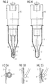
- Figure 1 shows a sensor in a first side view.
- FIG. 2 shows the sensor of FIG. 1 in a second, vertical side view.
- FIGS. 3A, 3B, 3C show different possibilities of Arrangement of an elastic material between the sensor and the sleeve.
- FIGS. 4 to 7 show different possibilities of Arrangement of the electrical connection elements or the Sleeve.
- FIG. 8 shows an electrical device
- Figure 1 shows a sensor with a plug 6, to whose Bottom a sensor 1 is suspended.
- the suspension of the Sensor 1 is effected by means of a contact element 71.
- Die Bottom of the plug 6 and the contact element 71 and the Sensor 1 are covered by a sleeve 2.
- a gap between the sensor 1 and the sleeve 2 is filled with a Mass 3.
- the mass 3 fills the entire space in the Sleeve 2, not from other elements of the probe is filled.
- the sleeve 2 has a tubular portion 21 and a constricted section 22.
- the tubular portion 21 is located in the upper part of the sleeve 2.
- the narrowed Section 22 or the constriction 22 is located in the lower part of the sleeve 2.
- a contact area 4 wherein the Contact area 4 is characterized in that it is free from Mass is 3. In other words, at this point prevails a direct contact between the sleeve 2 and the sensor 1, but still an intermediate layer or a Material between sensor 1 and sleeve 2 may be provided.
- the contact element 71 extends in the upper region parallel and Centric to the longitudinal central axis 61 of the plug 6. In the bottom Area is the contact element 71 slightly to the left side bent, whereby the contact area 4 between the sensor. 1 and the sleeve 2 comes about.
- Figure 1 shows the sensor in the assembled state. In the unassembled state, so in a state where the sleeve 2 has not yet been pushed over the sensor 1, results in a slightly different picture.
- the deviation of the electrical contact element 71 to left side is still slightly larger than in Figure 1 shown.
- this mechanism presupposes that the Contact element 71 has resilient properties, that is, that it when exerting a lateral deflection of the sensor 1 thereto is suitable, one acting against the deflection To produce spring force.
- a contact element to a copper wire or the like use.
- the contact element Materials such as copper, iron, nickel and their alloys.
- the sensor 1 may advantageously be a wired NTC sensor ceramic act. Such sensors are advantageously used to, for example, in Range of household appliances to capture temperatures.
- the wired NTC sensor is contacted on the plug 6.
- the plug 6 has contact elements on its upper side, the insertion of the plug 6 in a device allows where a signal from the sensor 1 forwarded or is processed.
- the sleeve 1 is preferably made of stainless steel and has preferably a wall thickness of 0.2 to 1.0 mm.
- the formation of the sleeve 2 made of stainless steel has the advantage that they also in chemically aggressive environment, for example in Washing liquors still have sufficient chemical stability having. Accordingly, it is advantageous here to use described probe in places where he directly comes in contact with corrosive liquids. Furthermore Stainless steel has the advantage that it conducts the heat well and thus hardly limiting on the thermal response time of the Probe works.
- the mass 3 may advantageously be a potting compound with relatively simple means to process.
- an epoxy resin as a two-component system to use, where advantageously the viscosity in terms of the elements used, in particular in terms of the stiffness of the contact elements, the shape the sleeve is optimized to easily insert the Sensor 1 and the contact element 71 to allow without causing resistance or bending the sensor or the contact element 71 comes.
- Figure 1 is still apparent that the transition from tubular area 21 in the constricted area 22 without Corners, but executed with gentle curves, thus the insertion of the sensor 1 in the sleeve 2 facilitates is reduced, and the risk is that the sensor 1 at a corner gets stuck.
- the mass 3 after production of the probe is generally cured, which means that during installation of the probe in the sleeve 2 still existing spring force possibly in the finished state of the Probe can no longer be detected.
- Figure 2 shows the sensor of Figure 1 in another Side view, namely rotated by 90 °. It is here In particular, it can be seen that for fastening the sensor 1 on the plug 6 next to the contact element 71 yet another Contact element 72 is provided. To be as good as possible to achieve mechanical stability on the plug 6, are the contact elements 71, 72 in the vicinity of the plug 6 with arranged relatively large distance from each other. Toward the sensor 1 then narrows the distance of the Contact elements 71, 72.
- FIG. 3A shows an embodiment of the contact region 4 a sensor according to Figure 1, where in the contact area between the sensor 1 and the sleeve 2 an elastic material is arranged.
- This elastic material is in the form of a Coating 51 of the sensor 1 is provided.
- material comes for example, consider the use of silicone in Compound with fillers which, for example, particles can be made of aluminum oxide.
- the material silicone has the Advantage that it has a good elasticity, and therefore to Degradation of thermo-mechanical stresses between the sleeve. 2 and the sensor 1 is well suited.
- the introduction of the Filler has the advantage that the thermal conductivity of the elastic material can be improved, which is the reducing the thermal response time of the probe helps.
- the coating 51 of the sensor 1 can, for example be prepared by immersing the sensor 1 in a corresponding liquid material, which subsequently the Coating 51 forms.
- Figure 3B shows an embodiment according to Figure 3A, wherein however, the elastic material is not in the form of a Coating the sensor, but in the form of a coating 52 of the sleeve 2 is provided.
- the coating 52 of the sleeve 2 may, for example be prepared by immersing the sleeve 2 in a bath with appropriate material or by vapor deposition or similar coating methods.
- the material for the coating 52 is the same material considering how it is used for the coating 51.
- Figure 3C shows yet another example of the embodiment the elastic material between the sensor 1 and the sleeve 2, wherein the material in the form of a between the sensor 1 and the sleeve 2 laid, separate, independent part is realized.
- it is a separate element 53, which consists of elastic material.
- a Possibility is using a rotationally symmetrical sleeve an eccentric arrangement of To reach the sensor to ensure that the sensor with the sleeve forms a contact area.
- Another possibility is a centric one Arrangement of the sensor to combine with an eccentric shaped sleeve, which in turn can cause sleeve and Sensor form a contact area.
- a third possibility is to use the sleeve with a To provide a narrowing into which the sensor just fits, so that the sensor when pushing the sleeve in this Constriction can be pushed, and thus a sensor with surrounded on all sides or only on opposite sides Contact area can be realized.
- FIG. 4 shows a possible embodiment of the invention Sensor, wherein the sensor 1 with respect to the Longitudinal center axis 61, which for both the plug 1 and applies to the sleeve 2, is arranged eccentrically.
- FIG assembled state of the probe shows. I'm not yet assembled state, so without the pushed over Sleeve 2, the eccentricity of the sensor 1 is larger, the means the distance of the sensor 1 to the longitudinal center axis or in this case symmetry axis 61 is larger as shown in Figure 4.
- FIG. 1 Another possibility, the eccentricity of the sensor 1 to reach is shown in FIG.
- Contact elements 71, 72 are provided, both in the upper Area, so close to the connector 6 as well as in the lower area, so close to the sensor 1 parallel to each other.
- the Contact elements 71, 72 are also parallel to Longitudinal central axis 61. However, they are not centric to the longitudinal central axis 61, but they are eccentric and cause thereby also the eccentricity of the sensor 1.
- Eccentricity of the sensor 1 can be well predetermined, man note, however, that as already stated in FIG. 4, the Difference between the condition before and after assembly or after pushing the sleeve 2 on the Sensor 1 exists. It will ultimately be assumed that also in FIG. 5, where this is not explicitly shown, a slight bending of the contact elements 71, 72 for right side is present here to the desired Spring pressure in the direction of the inner wall of the sleeve 2 upright to obtain.
- FIG. 1 Another way to realize the eccentricity is shown in FIG.
- the contact elements 71, 72 extend here parallel to each other, but in comparison to Longitudinal axis 61 at an angle to this. Further are the contact elements 71, 72 are not centered on the plug 6, but inserted eccentrically, which for example by inclined sockets at the bottom of the plug. 6 can be achieved. Moreover, with respect to the Positions of the sensor 1 in the assembled and not assembled state the same as in Figure 4 and Figure 5 said.
- FIG. 7 shows a further possibility of the eccentricity of the To reach sensor 1.
- the Eccentricity is achieved by a corresponding Forming of the sleeve 2, which on the right side in the Compared to the left side receives enlarged indentation and where ultimately the contact area 4 through this indentation is produced.
- the Insertion of the sensor 1 in the sleeve 2 one not here shown bending of the contact elements 71, 72 generates is what produces the desired effect of the spring pressure, the Press the sensor 1 against the inner wall of the sleeve 2.
- Figure 8 shows schematically an electrical device 8, with a sensor 9 of the type described here is equipped. It Furthermore, by way of example, a heater 10 is provided which is controlled by the sensor 9.
- the electrical device 8 may preferably be a Home appliance, such as a washing machine or a Tumble act. Especially in this application area Low thermal response times are needed. About that In addition, this is also in this one Application area often present an aggressive environment, so that the probe must be suitably encapsulated, whereby only the competing demands for thermal Response time on the one hand and good encapsulation on the other are justified.
- the probe described here, the method for his Manufacture and the electrical device are not on the here illustrated and described embodiments limited. They also include all experts Modifications and partial and sub-combinations of described and illustrated features and measures. she also includes all modifications and partial and Subcombinations of the features shown in the figures and measures.
- the invention is not limited to sensors, which are suitable for detecting a temperature. she rather, includes all sensors that have a physical size capture and is beneficial wherever it is arrives at that sensor as possible with its surroundings same temperature is.
Abstract
Description
Die Erfindung betrifft einen Meßfühler zum Erfassen von physikalischen Größen.The invention relates to a sensor for detecting physical sizes.
Ein solcher Fühler ist beispielsweise bekannt aus der Druckschrift DE 101 59 869 Al. Dort ist ein rastbarer Fühler zum Einstecken in die Bohrung eines Gehäuses beschrieben, wobei ein Fühlerkörper und ein Sensorelement durch Kontaktelemente miteinander verbunden sind. Ferner ist der Fühlerkörper mit einem Abdeckbügel zum Schutz des Sensors vor Abknicken versehen.Such a sensor is known for example from the DE 101 59 869 A1. There is a snap-in feeler described for insertion into the bore of a housing, wherein a sensor body and a sensor element by Contact elements are interconnected. Furthermore, the Sensor body with a cover bracket to protect the sensor Provided kinking.
Es ist Aufgabe der vorliegenden Erfindung, einen Fühler anzugeben, der eine niedrige thermische Ansprechzeit aufweist.It is an object of the present invention to provide a sensor specify a low thermal response time having.
Diese Aufgabe wird gelöst durch einen Fühler nach
Patentanspruch 1. Vorteilhafte Ausgestaltungen des Fühlers
sind den weiteren Patentansprüchen zu entnehmen.This task is solved by a
Es wird ein Meßfühler angegeben, der einen Sensor umfaßt, welcher in einer Hülse angeordnet ist. Der Zwischenraum zwischen dem Sensor und der Hülse ist mit einer Masse gefüllt. Ein Kontaktbereich zwischen dem Sensor und der Hülse ist frei von der Masse. Der Sensor ist vorteilhafterweise zum Erfassen von Temperaturen geeignet.A sensor is provided which comprises a sensor, which is arranged in a sleeve. The gap between the sensor and the sleeve is with a mass filled. A contact area between the sensor and the sleeve is free from the crowd. The sensor is advantageously for Detecting temperatures suitable.
Der hier angegebene Meßfühler nutzt als allgemeinen Erfindungsgedanken die Idee, durch das Vorsehen eines Kontaktbereichs zwischen dem Sensor und der Hülse die Wärmeleitung von außen durch die Hülse auf den Sensor zu verbessern. Dadurch sinkt die thermische Ansprechzeit für den Fühler. Die Einbettung des Sensors in die Masse ist vorteilhaft zur Fixierung der einzelnen Systemelemente und um die mechanische Belastbarkeit, insbesondere gegenüber Vibrationen, zu verbessern. Jedoch ist der Sensor nicht allseitig von der Masse umgeben, sondern es gibt einen massefreien Bereich, mit dem der Sensor mit der Hülse in Kontakt steht. Dieser von der Masse freie Bereich ist insbesondere dazu geeignet, für eine gute Wärmeleitung von außen, also von der Seite der Hülse in den Sensor zu sorgen. Als Material für die Masse, in die der Sensor eingebettet ist, werden oftmals Materialien verwendet, die schlecht wärmeleitend sind und die bei allseitiger Einbettung des Sensors eine hohe thermische Ansprechzeit zur Folge hätten.The probe specified here uses as a general The idea of the invention, by providing a Contact area between the sensor and the sleeve the Heat conduction from outside through the sleeve towards the sensor improve. This reduces the thermal response time for the Sensor. The embedding of the sensor in the mass is advantageous for fixing the individual system elements and order the mechanical strength, especially against Vibrations, improve. However, the sensor is not surrounded on all sides by the mass, but there is one mass-free area, with which the sensor with the sleeve in Contact stands. This is a mass-free area especially suitable for good heat conduction of on the outside, ie from the side of the sleeve into the sensor. As material for the mass into which the sensor is embedded is often materials are used that bad are thermally conductive and the all - sided embedding of Sensors would have a high thermal response time.
Es kann vorteilhafter Weise vorgesehen sein, daß im Kontaktbereich der Sensor direkt an der Hülse anstößt. In diesem Fall ist ein guter Wärmetransport von der Hülse zum Sensor sichergestellt, da keine dazwischenliegenden Materialien oder Schichten vom Wärmestrom durchquert werden müssen.It can be advantageously provided that in Contact area of the sensor abuts directly on the sleeve. In In this case, a good heat transfer from the sleeve to Sensor ensured, since no intermediate Materials or layers are traversed by the heat flow have to.
In einer anderen Ausführungsform des Fühlers ist im Kontaktbereich zwischen der Hülse und dem Sensor ein elastisches Material angeordnet. Das elastische Material hat den Vorteil, daß es dem Abbau thermomechanischer Spannungen zwischen dem Sensor und der Hülse dienen kann. Thermomechanische Spannungen können beispielsweise resultieren aus einem Unterschied im thermischen Ausdehnungskoeffizienten der Hülse einerseits und des Sensors andererseits. In another embodiment of the sensor is in Contact area between the sleeve and the sensor arranged elastic material. The elastic material has the advantage that it is the degradation of thermo-mechanical stresses can serve between the sensor and the sleeve. Thermo-mechanical stresses can, for example result from a difference in thermal Expansion coefficients of the sleeve on the one hand and the sensor on the other hand.
Das elastische Material kann in Form einer Beschichtung des Sensors vorliegen. In diesem Fall hätte der Sensor eine äußere Hülle, die aus dem elastischen Material besteht. Beispielsweise kann der Sensor allseitig von einer solchen Hülle umgeben sein. In diesem Fall könnte die Hülle beispielsweise durch Eintauchen in ein entsprechendes flüssiges Material hergestellt werden.The elastic material may take the form of a coating of the Sensors are present. In this case, the sensor would have a outer shell, which consists of the elastic material. For example, the sensor on all sides of such Be surrounded by a shell. In this case, the shell could for example by immersion in a corresponding be made liquid material.
In einer anderen Ausführungsform des Meßfühlers kann das elastische Material auch als Beschichtung auf der Innenseite der Hülse vorgesehen sein.In another embodiment of the probe, the elastic material also as a coating on the inside be provided of the sleeve.
Darüber hinaus ist es auch denkbar, das elastische Material als separates Element vorzusehen, das zwischen der Hülse und dem Sensor angeordnet wird.In addition, it is also conceivable, the elastic material to provide as a separate element between the sleeve and the sensor is arranged.
In einer Ausführungsform des Meßfühlers kann die Masse eine Vergußmasse sein. Dabei können als Vergußmasse die üblicherweise für solche Zwecke verwendeten Materialien zum Einsatz gelangen.In one embodiment of the probe, the mass may be a Be potting compound. It can be used as potting the commonly used materials for such purposes Get used.
Dies hat den Vorteil, daß nicht Entwicklungsaufwand für die Herstellung einer speziell für den hier beschriebenen Zweck geeignete Masse betrieben werden muß. Insbesondere schlecht wärmeleitende Vergußmassen sind hier geeignet, da die niedrige thermische Ansprechzeit durch den Kontaktbereich garantiert wird.This has the advantage that no development effort for the Preparation of a purpose specifically for the purpose described here suitable mass must be operated. Especially bad thermally conductive potting compounds are suitable here, as the low thermal response time through the contact area is guaranteed.
In einer vorteilhaften Ausführungsform weist die Hülse einen rohrförmigen Abschnitt und eine Verengung auf. Unter einen rohrförmigen Abschnitt ist ein Abschnitt der Hülse zu verstehen, der entlang einer Längsmittelachse des rohrförmigen Abschnitts eine gleichbleibende Querschnittsform und -fläche aufweist. Demgegenüber ist unter einer Verengung ein Abschnitt der Hülse zu verstehen, wo sich der die Querschnittsfläche entlang der Längsmittelachse der Hülse in eine Richtung verkleinert. Das Verkleinern des Querschnitts muß nicht notwendigerweise über die gesamten Länge der Verengung gegeben sein, vielmehr kann die Verengung auch Abschnitte aufweisen, in denen ein gegenüber dem rohrförmigen Abschnitt zwar verkleinerter Querschnitt vorliegt, dieser aber über einen bestimmten Abschnitt der Längsmittelachse gleich bleibt. Insbesondere kann die Verengung auch den Abschluß der Hülse auf einer Seite der Hülse umfassen. Dies bedeutet, daß die Hülse im Bereich der Verengung auch geschlossen ist.In an advantageous embodiment, the sleeve has a tubular section and a narrowing up. Under one tubular section is a section of the sleeve too understand that along a longitudinal center axis of the tubular section a consistent cross-sectional shape and area. In contrast, is under a narrowing a section of the sleeve to understand where the the Cross-sectional area along the longitudinal center axis of the sleeve in one way down. Shrinking the cross section does not necessarily have the entire length of Narrowing can be given, rather, the narrowing can also Have sections in which one opposite the tubular Section although reduced cross-section is present, this but over a certain section of the longitudinal center axis stays the same. In particular, the narrowing can also Include completion of the sleeve on one side of the sleeve. This means that the sleeve in the area of the narrowing as well closed is.
Die Aufteilung der Hülse in einen relativ zur Verengung breiten rohrförmigen Abschnitt und einen Abschnitt, der die Verengung darstellt hat den Vorteil, daß der hier beschriebene Meßfühler leicht durch Einschieben eines an Elementen aufgehängten Sensors ein die Hülse hergestellt werden kann, wobei ein breiter Anfangsbereich beim Einschieben die Positionierung des Sensors erleichtert und der anschließende verjüngte beziehungsweise verengte Bereich der Hülse das Herstellen des Kontaktbereichs zwischen dem Sensor und der Hülseninnenwand erleichtert.The division of the sleeve into a relative to the constriction wide tubular section and a section that the Constriction has the advantage of being here described sensor easily by inserting a Elements suspended sensor made a sleeve can be, with a wide initial range when Inserting the positioning of the sensor facilitates and the subsequent tapered or narrowed area the sleeve making the contact area between the Sensor and the sleeve inner wall facilitates.
Dementsprechend ist bei einer vorteilhaften Ausgestaltung des Meßfühlers der Kontaktbereich im Bereich der Verengung der Hülse vorgesehen.Accordingly, in an advantageous embodiment of the Sensor of the contact area in the area of the constriction of the Sleeve provided.
Die Hülse beziehungsweise die Verengung der Hülse kann mit einem schrägstehenden Hülsenabschnitt versehen sein. Das bedeutet, daß die Verengung der Hülse Seitenwände aufweist, die schräg zur Längsmittelachse der Hülse stehen. An diesen schrägstehenden Hülsenwänden kann der Sensor beim Einschieben in die Hülse leicht entlang gleiten um später auf seine endgültige Position am Kontaktbereich zu treffen.The sleeve or the constriction of the sleeve can with be provided an inclined sleeve portion. The means that the constriction of the sleeve has side walls, which are inclined to the longitudinal center axis of the sleeve. At this Slanting sleeve walls, the sensor when inserting Slightly slide along the sleeve to later on his final position at the contact area.
Darüber hinaus ist es vorteilhaft, wenn der Übergang zwischen dem rohrförmigen Abschnitt und der Verengung der Hülse frei von Kanten ausgeführt ist. Diese Ausgestaltung der Hülse hat den Vorteil, daß beim Entlanggleiten des Sensors an der Hülseninnenwand ein Verhaken zwischen der Hülseninnenwand und dem Sensor verhindert werden kann.In addition, it is beneficial when the transition between the tubular portion and the constriction of the sleeve free is executed by edges. This embodiment of the sleeve has the advantage that when sliding along the sensor at the Sleeve inner wall a hooking between the sleeve inner wall and the sensor can be prevented.
In einer anderen Ausführungsform des Meßfühlers ist ein Stecker vorgesehen, wobei der Sensor mittels wenigstens eines Kontaktelementes mit dem Stecker verbunden ist. Die Kontaktelemente sind dabei vorteilhafterweise so ausgeführt, daß bei seitlicher Auslenkung des Sensors beziehungsweise der Kontaktelemente eine Federkraft erzeugt wird, die entgegen der Auslenkung wirkt. Die Anzahl der Kontaktelemente kann dabei zwischen 1, 2 und auch einer noch größeren Anzahl von solchen Elementen variieren. Vorzugsweise beträgt die Anzahl der Kontaktelemente zwei, nämlich je ein Element für die zwei elektrischen Pole einer Spannungsversorgung des Sensors.In another embodiment of the probe is a Plug provided, wherein the sensor by means of at least one Contact element is connected to the plug. The Contact elements are advantageously designed so that at lateral deflection of the sensor or the Contact elements a spring force is generated, the opposite the deflection acts. The number of contact elements can between 1, 2 and also an even larger number of vary such elements. Preferably, the number is the contact elements two, namely one element for the two electrical poles of a voltage supply of the sensor.
Diese Ausführungsform des Meßfühlers hat den Vorteil, daß beim Zusammenschieben des Sensors und der Hülse durch Entlanggleiten des Sensors an der Hülseninnenwand eine Federkraft aufgebaut werden kann, die den Sensor gegen die Hülseninnenwand drückt und somit für eine sichere Ausgestaltung des Kontaktbereiches sorgt.This embodiment of the probe has the advantage that when pushing the sensor and the sleeve through Along the sliding of the sensor on the sleeve inner wall a Spring force can be built up, which the sensor against the Sleeve inner wall presses and thus for a safe Design of the contact area ensures.
Gemäß einer anderen Ausführungsform des Meßfühlers ist eine Hülse vorgesehen, die exzentrisch zu einer Längsmittelachse der Hülse gestaltet ist. According to another embodiment of the probe is a Sleeve provided, which is eccentric to a longitudinal central axis the sleeve is designed.
Eine solche exzentrische Hülse kann dazu verwendet werden, ein an sich zentrisch angeordnetes beziehungsweise zentrisch gestaltetes Element enthaltend einen Stecker, elektrische Verbindungselemente beziehungsweise Kontaktelemente und den Sensor durch Aufschieben der exzentrischen Hülse so zu konfigurieren, daß der Sensor am exzentrischen Teil der Hülseninnenwand anliegt und somit den gewünschten Kontaktbereich bildet.Such an eccentric sleeve can be used a centrically arranged per se or centric designed element containing a plug, electrical Connecting elements or contact elements and the Sensor by sliding the eccentric sleeve so too configure the sensor on the eccentric part of the Sleeve inner wall rests and thus the desired Contact area forms.
Es wird darüber hinaus ein Verfahren zur Herstellung des
Meßfühlers angegeben, wobei das Verfahren die folgenden
Schritte umfaßt:
Vorteilhafterweise kann in einem darauf folgenden Schritt noch der Stecker mit der Hülse verbunden werden, um einen mechanisch stabilen, kompakten Aufbau zu erzielen.Advantageously, in a subsequent step still the plug can be connected to the sleeve to one to achieve a mechanically stable, compact construction.
Das hier angegebene Verfahren macht sich den Grundgedanken zu nutze, wonach durch die letzten Endes trichterförmige Gestaltung, also die sich nach unten hin verjüngende Gestaltung der Hülse ein einfaches Einschieben des Sensors in die Hülse erzielen läßt. Der Sensor kann an der Innenwand der Hülse entlang gleiten und befindet sich nach Ende des Einschubvorgangs, insbesondere dann, wenn der Sensor während des Einschiebens federnd an der Hülseninnenwand anliegt, automatisch in einem Kontaktbereich mit der Hülse, wo ein unmittelbarer, von Masse freier Kontakt mit der Hülseninnenwand gewährleistet ist.The procedure given here is the basic idea use, after which by the last end funnel-shaped Design, so the tapering down Design of the sleeve a simple insertion of the sensor in can achieve the sleeve. The sensor can be attached to the inner wall of the Slide along sleeve and is located at the end of the Insertion process, especially if the sensor during the insertion resiliently abuts the sleeve inner wall, automatically in a contact area with the sleeve, where a Immediate, ground-free contact with the Sleeve inner wall is guaranteed.
Insbesondere in Verbindung mit Kontaktelementen, die federnde Eigenschaften haben, ergibt sich der Vorteil, daß durch das Entlanggleiten des Sensors an der schrägen Hülseninnenwand ein dauernder sicherer mechanischer Kontakt zwischen dem Sensor und der Hülse gewährleistet ist, der von Anfang der ersten Berührung des Sensors mit der Hülseninnenwand bis zum Ende des Einschubvorgangs bestehen kann und somit einen sicheren Kontaktbereich fordert.Especially in connection with contact elements, the resilient Have properties, there is the advantage that through the Along the sliding of the sensor on the oblique sleeve inner wall a permanent secure mechanical contact between the Sensor and the sleeve is guaranteed, from the beginning of first contact of the sensor with the sleeve inner wall to the End of the insertion process can exist and thus one secure contact area calls.
Dementsprechend ist ein Verfahren zur Herstellung des Meßfühlers besonders vorteilhaft, wobei die Kontaktelemente so gestaltet sind, daß sie während des Entlanggleitens des Sensors an der Innenwand diesen mittels einer Federkraft gegen die Innenwand drücken.Accordingly, a method for producing the Sensor particularly advantageous, wherein the contact elements are designed so that they move during the slippage of the Sensor on the inner wall by means of a spring force press against the inner wall.
Des weiteren ist es vorteilhaft, wenn bei einem hier angegebenen Verfahren zur Herstellung Meßfühlers die Viskosität der Masse in der Hülse so gewählt wird, daß der Sensor ohne wesentliche Verbiegung der Kontaktelemente durch die Masse gleiten kann.Furthermore, it is beneficial if at one here specified method for producing probe the Viscosity of the mass in the sleeve is chosen so that the Sensor without significant bending of the contact elements by the mass can slide.
Durch eine solche Ausgestaltung des Verfahrens wird mittels Wahl einer relativ niedrigen Viskosität der Masse, beispielsweise der Vergußmasse, gewährleistet, daß die Vergußmasse kein wesentliches Hindernis für das Einführen des Sensors in die Hülse darstellt.By such an embodiment of the method is by means of Choosing a relatively low viscosity of the mass, for example, the potting compound, ensures that the Potting compound is not a major obstacle to the introduction of the Sensor in the sleeve represents.
Es wird darüber hinaus ein elektrisch betriebenes Gerät angegeben, das einen hier beschriebenen Meßfühler als Temperatursensor enthält.It also becomes an electrically operated device indicated that a sensor described here as Temperature sensor contains.
Durch den robusten, von einer Hülse geschützten Sensor kann gewährleistet werden, daß der hier beschriebene Fühler auch unter belastenden Außenbedingungen, beispielsweise in stark alkalischen und daher ätzenden Waschlaugen problemlos über eine lange Lebensdauer eingesetzt werden kann. Der Meßfühler kann beispielsweise dazu verwendet werden, in Waschmaschinen oder in Wäschetrocknern als Temperatursensor zu funktionieren. Mittels des Sensors wird die Temperatur gemessen und eine Temperaturregelvorrichtung innerhalb des elektrischen Geräts, vorzugsweise elektrischen Haushaltsgeräts, gesteuert.The robust, protected by a sleeve sensor can be ensured that the sensor described here also under stressful outdoor conditions, for example in strong alkaline and therefore caustic suds easily over a long life can be used. The sensor For example, it can be used in washing machines or in tumble dryers as a temperature sensor function. By means of the sensor the temperature becomes measured and a temperature control device within the electrical device, preferably electrical Household appliance, controlled.
Im folgenden wird der Meßfühler und ein elektrisches Gerät anhand von Ausführungsbeispielen näher erläutert.The following is the sensor and an electrical device explained in more detail with reference to embodiments.
Figur 1 zeigt einen Meßfühler in einer ersten Seitenansicht.Figure 1 shows a sensor in a first side view.
Figur 2 zeigt den Meßfühler aus Figur 1 in einer zweiten, dazu senkrechten Seitenansicht. FIG. 2 shows the sensor of FIG. 1 in a second, vertical side view.
Die Figuren 3A, 3B, 3C zeigen verschiedene Möglichkeiten der Anordnung eines elastischen Materials zwischen dem Sensor und der Hülse.FIGS. 3A, 3B, 3C show different possibilities of Arrangement of an elastic material between the sensor and the sleeve.
Die Figuren 4 bis 7 zeigen verschiedene Möglichkeiten der Anordnung der elektrischen Verbindungselemente bzw. der Hülse.FIGS. 4 to 7 show different possibilities of Arrangement of the electrical connection elements or the Sleeve.
Figur 8 zeigt ein elektrisches Gerät.FIG. 8 shows an electrical device.
Figur 1 zeigt einen Meßfühler mit einem Stecker 6, an dessen
Unterseite ein Sensor 1 aufgehängt ist. Die Aufhängung des
Sensors 1 erfolgt mittels eines Kontaktelementes 71. Die
Unterseite des Steckers 6 sowie das Kontaktelement 71 und der
Sensor 1 sind von einer Hülse 2 bedeckt. Ein Zwischenraum
zwischen dem Sensor 1 und der Hülse 2 ist gefüllt mit einer
Masse 3. Die Masse 3 füllt dabei den gesamten Raum in der
Hülse 2 auf, der nicht von anderen Elementen des Meßfühlers
ausgefüllt ist.Figure 1 shows a sensor with a
Die Hülse 2 weist einen rohrförmigen Abschnitt 21 und einen
verengten Abschnitt 22 auf. Der rohrförmige Abschnitt 21
befindet sich im oberen Bereich der Hülse 2. Der verengte
Abschnitt 22 beziehungsweise die Verengung 22 befindet sich
im unteren Teil der Hülse 2. Im unteren Teil der Hülse 2 ist
auch ein Kontaktbereich 4 vorgesehen, wobei der
Kontaktbereich 4 sich dadurch auszeichnet, daß er frei von
Masse 3 ist. Mit anderen Worten, an dieser Stelle herrscht
ein direkter Kontakt zwischen der Hülse 2 und dem Sensor 1,
wobei jedoch noch eine Zwischenschicht beziehungsweise ein
Material zwischen Sensor 1 und Hülse 2 vorgesehen sein kann. The
Das Kontaktelement 71 verläuft im oberen Bereich parallel und
zentrisch zur Längsmittelachse 61 des Steckers 6. Im unteren
Bereich ist das Kontaktelement 71 leicht zur linken Seite
gebogen, wodurch der Kontaktbereich 4 zwischen dem Sensor 1
und der Hülse 2 zustande kommt. Hierbei ist zu beachten, daß
die Figur 1 den Meßfühler im zusammengebauten Zustand zeigt.
Im nicht zusammengebauten Zustand, also in einem Zustand wo
die Hülse 2 noch nicht über den Sensor 1 geschoben ist,
ergibt sich ein etwas anderes Bild. Hier ist es vorgesehen,
daß die Abweichung des elektrischen Kontaktelements 71 zur
linken Seite noch etwas größer ist als in Figur 1
dargestellt. Dies bedeutet, daß beim Einschieben des Sensors
1 in die Hülse 2 der nach links gebogene Sensor 1 - gesehen
in Einschubrichtung - etwa im mittleren Bereich der Verengung
22 an die Innenwand der Hülse 2 anstößt und an der Innenwand
entlang nach unten zum Kontaktbereich 4 wandert. Während
dieser Wanderung nach unten an der Innenwand der Hülse 2
entlang verengt sich die Hülse 2 zunehmend, was bedeutet, daß
das Kontaktelement 71 zunehmend nach rechts gebogen wird und
eine entsprechende, sich im allgemeinen verstärkende
Federkraft wirkt, die den Sensor 1 gegen die Innenwand der
Hülse 2 drückt.The
Dieser Mechanismus setzt allerdings voraus, daß das
Kontaktelement 71 federnde Eigenschaften hat, das heißt, daß
es bei Ausüben einer seitlichen Auslenkung des Sensors 1 dazu
geeignet ist, eine entgegen der Auslenkung wirkende
Federkraft zu erzeugen. Beispielsweise kommt es in Betracht
als Kontaktelement eine Kupferdraht oder ähnliches zu
verwenden. Geeignet für das Kontaktelement sind auch
Materialien wie Kupfer, Eisen, Nickel und deren Legierungen. However, this mechanism presupposes that the
Bei dem Sensor 1 kann es sich vorteilhafterweise um einen
bedrahteten NTC-Sensor aus Keramik handeln. Solche Sensoren
werden vorteilhafterweise eingesetzt, um beispielsweise im
Bereich der Haushaltsgeräte Temperaturen zu erfassen.The
Der bedrahtete NTC-Sensor ist auf dem Stecker 6 kontaktiert.The wired NTC sensor is contacted on the
Der Stecker 6 weist an seiner Oberseite Kontaktelemente auf,
die das Einstecken des Steckers 6 in eine Vorrichtung
ermöglicht, wo ein Signal des Sensors 1 weitergeleitet
beziehungsweise verarbeitet wird.The
Die Hülse 1 besteht vorzugsweise aus Edelstahl und weist
vorzugsweise eine Wandstärke von 0,2 bis 1,0 mm auf.The
Die Ausbildung der Hülse 2 aus Edelstahl hat den Vorteil, daß
sie auch in chemisch aggressiver Umgebung, beispielsweise in
Waschlaugen noch eine genügende chemische Stabilität
aufweist. Dementsprechend ist es vorteilhaft, den hier
beschriebenen Meßfühler an Stellen einzusetzen, wo er direkt
in Kontakt mit ätzenden Flüssigkeiten kommt. Darüber hinaus
hat Edelstahl den Vorteil, daß es gut die Wärme leitet und
somit kaum begrenzend auf die thermische Ansprechzeit des
Meßfühlers wirkt.The formation of the
Die Masse 3 kann vorteilhaft eine Vergußmasse sein, die mit
relativ einfachen Mitteln zu verarbeiten ist. Beispielsweise
kommt es in Betracht ein Epoxidharz als Zwei-Komponenten-System
zu verwenden, wobei vorteilhafterweise die Viskosität
hinsichtlich der verwendeten Elemente, insbesondere
hinsichtlich der Steifigkeit der Kontaktelemente, der Form
der Hülse optimiert wird, um problemlos das Einführen des
Sensors 1 beziehungsweise des Kontaktelements 71 zu
ermöglichen, ohne daß es zu Widerständen oder zu Verbiegungen
des Sensors beziehungsweise des Kontaktelements 71 kommt.The mass 3 may advantageously be a potting compound with
relatively simple means to process. For example
it comes into consideration an epoxy resin as a two-component system
to use, where advantageously the viscosity
in terms of the elements used, in particular
in terms of the stiffness of the contact elements, the shape
the sleeve is optimized to easily insert the
Figur 1 ist noch zu entnehmen, daß der Übergang vom
rohrförmigen Bereich 21 in den verengten Bereich 22 ohne
Ecken, sondern mit sanften Rundungen ausgeführt ist, wodurch
das Einschieben des Sensors 1 in die Hülse 2 erleichtert
wird, und die Gefahr vermindert wird, daß der Sensor 1 an
einer Ecke hängen bleibt.Figure 1 is still apparent that the transition from
Bei dem in Figur 1 dargestellten Meßfühler wird die
Wärmeeinkopplung nur noch von der Wärmeleitfähigkeit der
Hülse 2 und vom Wärmeübergang von der Hülse 2 auf den Sensor
1 beeinflusst. Die Wärmeleitung über die Masse 3, die
üblicherweise eine relativ schlechte Wärmeleitfähigkeit
aufweist, fällt kaum noch ins Gewicht.In the probe shown in Figure 1, the
Heat input only from the thermal conductivity of the
Insbesondere gelingt es dadurch, die thermische Ansprechzeit des Meßfühlers zu reduzieren.In particular, it is possible by the thermal response time to reduce the probe.
Dabei wird unter der thermischen Ansprechzeit diejenige Zeitspanne verstanden, die ein auf 25 °C temperierter, und entlasteter Heißleiter benötigt, um sich - eingetaucht in ein Medium von 85 °C - auf 62,9 °C zu erwärmen. Dabei ist die thermische Ansprechzeit ebenso wie die thermische Abkühlzeitkonstante abhängig vom umgebenden Medium.It is the one under the thermal response time Period of time understood that tempered to 25 ° C, and Relieved thermistor needed to get - immersed in a Medium from 85 ° C - to 62.9 ° C to warm. It is the thermal response time as well as the thermal Cooling time constant depending on the surrounding medium.
Deshalb werden möglichst standardisierte Medien verwendet für den Vergleich verschiedener Meßfühler untereinander.Therefore as standardized as possible media are used for the comparison of different sensors with each other.
Es ist noch zu beachten, daß die Masse 3 nach der Herstellung
des Fühlers im allgemeinen ausgehärtet wird, was bedeutet,
daß die beim Einbau des Fühlers in die Hülse 2 noch
vorhandene Federkraft möglicherweise im fertigen Zustand des
Meßfühlers nicht mehr festgestellt werden kann.It should be noted that the mass 3 after production
of the probe is generally cured, which means
that during installation of the probe in the
Figur 2 zeigt den Meßfühler aus Figur 1 in eine anderen
Seitenansicht, nämlich um 90 ° verdreht. Es ist hier
insbesondere zu erkennen, daß zur Befestigung des Sensors 1
am Stecker 6 neben dem Kontaktelement 71 noch ein weiteres
Kontaktelement 72 vorgesehen ist. Um eine möglichst gute
mechanische Stabilität auf dem Stecker 6 zu erzielen, sind
die Kontaktelemente 71, 72 in der Nähe des Steckers 6 mit
relativ großem Abstand zueinander angeordnet. In Richtung auf
den Sensor 1 hin verengt sich dann der Abstand der
Kontaktelemente 71, 72.Figure 2 shows the sensor of Figure 1 in another
Side view, namely rotated by 90 °. It is here
In particular, it can be seen that for fastening the
Im übrigen ist in der Zusammenschau von Figur 1 und Figur 2
zu erkennen, daß die Kontaktelemente 71, 72 nicht in einer
Ebene liegen, sondern daß vielmehr das seitliche Verbiegen
der Kontaktelemente 71, 72 so gestaltet ist, daß beide
Kontaktelemente in gleicher Weise verbogen sind. Das heißt,
daß die Richtung der Verbiegung der Kontaktelemente senkrecht
steht auf der die Kontaktelemente 71, 72 im unverbogenen
Zustand verbindenden Ebene.Incidentally, in the synopsis of Figure 1 and Figure 2
to recognize that the
Dadurch kann gewährleistet werden, daß beide Kontaktelemente
71, 72 in gleichem Maße verbogen werden und auch im gleichen
Maße zum Aufbau der Federkraft, die für den Einbau des
Sensors 1 in die Hülse 2 vorteilhaft ist, beitragen.This can ensure that both
Figur 3A zeigt eine Ausführungsform des Kontaktbereichs 4
eines Meßfühlers gemäß Figur 1, wo im Kontaktbereich zwischen
dem Sensor 1 und der Hülse 2 ein elastisches Material
angeordnet ist. Dieses elastische Material ist in Form einer
Beschichtung 51 des Sensors 1 vorgesehen. Als Material kommt
beispielsweise in Betracht die Verwendung von Silikon in
Verbindung mit Füllstoffen, welche beispielsweise Partikel
aus Aluminiumoxid sein können. Das Material Silikon hat den
Vorteil, daß es eine gute Elastizität aufweist, und daher zum
Abbau von thermomechanischen Spannungen zwischen der Hülse 2
und dem Sensor 1 gut geeignet ist. Das Einbringen des
Füllstoffs hat den Vorteil, daß die Wärmeleitfähigkeit des
elastischen Material verbessert werden kann, was die
thermische Ansprechzeit des Meßfühlers reduzieren hilft.FIG. 3A shows an embodiment of the contact region 4
a sensor according to Figure 1, where in the contact area between
the
Die Beschichtung 51 des Sensors 1 kann beispielsweise
hergestellt werden durch Eintauchen des Sensors 1 in eine
entsprechendes flüssiges Material, welches anschließend die
Beschichtung 51 bildet.The
Figur 3B zeigt ein Ausführungsbeispiel gemäß Figur 3A, wobei
jedoch das elastische Material nicht in Form einer
Beschichtung des Sensors, sondern in Form einer Beschichtung
52 der Hülse 2 vorgesehen ist.Figure 3B shows an embodiment according to Figure 3A, wherein
however, the elastic material is not in the form of a
Coating the sensor, but in the form of a
Die Beschichtung 52 der Hülse 2 kann beispielsweise
hergestellt werden durch Eintauchen der Hülse 2 in ein Bad
mit entsprechendem Material oder durch Aufdampfen oder
ähnliche Beschichtungsmethoden.The
Als Material für die Beschichtung 52 kommt das selbe Material
in Betracht, wie es für die Beschichtung 51 verwendet wird.The material for the
Figur 3C zeigt noch ein weiteres Beispiel für die Ausführung
des elastischen Materials zwischen dem Sensor 1 und der Hülse
2, wobei das Material in Form eines zwischen den Sensor 1 und
der Hülse 2 gelegten, separaten, eigenständigen Teils
realisiert wird. In diesem Fall handelt es sich um ein
separates Element 53, das aus elastischem Material besteht.Figure 3C shows yet another example of the embodiment
the elastic material between the
Das hier beschriebene allgemeine Prinzip eines Meßfühlers kann auf verschiedenen Wegen erreicht werden. Eine Möglichkeit besteht darin unter Verwendung einer rotationssymmetrischen Hülse eine exzentrische Anordnung des Sensors zu erreichen, um sicherzustellen, daß der Sensor mit der Hülse einen Kontaktbereich bildet.The general principle of a sensor described here can be achieved in different ways. A Possibility is using a rotationally symmetrical sleeve an eccentric arrangement of To reach the sensor to ensure that the sensor with the sleeve forms a contact area.
Eine andere Möglichkeit besteht darin, eine zentrische Anordnung des Sensors zu kombinieren mit einer exzentrisch geformten Hülse, was wiederum dazu führen kann, daß Hülse und Sensor einen Kontaktbereich bilden.Another possibility is a centric one Arrangement of the sensor to combine with an eccentric shaped sleeve, which in turn can cause sleeve and Sensor form a contact area.
Ein dritte Möglichkeit besteht darin, die Hülse mit einer Verengung zu versehen, in die der Sensor gerade hineinpaßt, so daß der Sensor beim Aufschieben der Hülse in diese Verengung geschoben werden kann, und somit ein Sensor mit allseitig oder auf nur gegenüber liegenden Seiten umgebenen Kontaktbereich realisiert werden kann.A third possibility is to use the sleeve with a To provide a narrowing into which the sensor just fits, so that the sensor when pushing the sleeve in this Constriction can be pushed, and thus a sensor with surrounded on all sides or only on opposite sides Contact area can be realized.
Die Figur 4 zeigt eine mögliche Ausführungsform des
Meßfühlers, wobei der Sensor 1 in Bezug auf die
Längsmittelachse 61, welche sowohl für den Stecker 1 als auch
für die Hülse 2 gilt, exzentrisch angeordnet ist. Diese
Exzentrizität wird erreicht, in dem die Kontaktelemente 71,
72 in einem Abschnitt, der in der Nähe des Steckers 6 liegt
parallel zur Längsmittelachse 61 und auch zentrisch zu dieser
Längsmittelachse 61 aus dem Stecker 6 herausgeführt werden.
Dies gelingt beispielsweise durch Vorsehen entsprechender
kleiner Steckbuchsen, falls die Kontaktelemente 71, 72 als
Drähte ausgeführt sind. FIG. 4 shows a possible embodiment of the invention
Sensor, wherein the
Im unteren Bereich der Kontaktelemente 71, 72 sind diese
gemäß Figur 4 etwas zur linken Seite gebogen, so daß eine
Exzentrizität für die Lage des Sensors 1 resultiert. Es ist
jedoch darauf hinzuweisen, daß Figur lediglich den
zusammengebauten Zustand des Meßfühlers zeigt. Im noch nicht
zusammengebauten Zustand, also ohne die darüber geschobene
Hülse 2 ist die Exzentrizität des Sensors 1 größer, das
heißt, der Abstand des Sensors 1 zur Längsmittelachse
beziehungsweise in diesem Fall Symmetrieachse 61 ist größer
als in Figur 4 dargestellt. Durch Aufschieben der Hülse 2
wird der Sensor 1 von dem verengten Abschnitt der Hülse 2
nach innen gedrückt, wo er dann schließlich unter einer
Federkraft an der Hülse 2 anliegt, wobei jedoch die
Exzentrizität und damit der Abstand des Sensors 1 zur
Längsmittelachse 61 geringer wird.In the lower region of the
Eine weitere Möglichkeit, die Exzentrizität des Sensors 1 zu
erreichen ist in Figur 5 dargestellt. Hier sind
Kontaktelemente 71, 72 vorgesehen, die sowohl im oberen
Bereich, also nahe am Stecker 6 als auch im unteren Bereich,
also nahe am Sensor 1 parallel zueinander verlaufen. Die
Kontaktelemente 71, 72 verlaufen auch parallel zur
Längsmittelachse 61. Allerdings liegen sie nicht zentrisch
zur Längsmittelachse 61, sondern sie liegen exzentrisch und
bewirken dadurch auch die Exzentrizität des Sensors 1. Durch
die Lage der Kontaktelemente 71, 72 im Stecker 6 kann so die
Exzentrizität des Sensors 1 gut vorherbestimmt werden, man
beachte jedoch, daß wie schon in Figur 4 ausgeführt, der
Unterschied zwischen dem Zustand vor und nach dem Zusammenbau
beziehungsweise nach dem Aufschieben der Hülse 2 auf den
Sensor 1 besteht. Dabei wird letztlich davon auszugehen sein,
daß auch in Figur 5, wo dies nicht explizit dargestellt ist,
eine leichte Verbiegung der Kontaktelemente 71, 72 zur
rechten Seite hin vorhanden ist, um hier den gewünschten
Federdruck in Richtung auf die Innenwand der Hülse 2 aufrecht
zu erhalten.Another possibility, the eccentricity of the
Eine weitere Möglichkeit, die Exzentrizität zu realisieren
ist in Figur 6 gezeigt. Die Kontaktelemente 71, 72 verlaufen
hier parallel zueinander, jedoch im Vergleich zur
Längsmittelachse 61 in einem Winkel zu dieser. Ferner sind
die Kontaktelemente 71, 72 am Stecker 6 nicht zentrisch,
sondern exzentrisch eingesteckt, was beispielsweise durch
schräg stehende Buchsen am unteren Ende des Steckers 6
erreicht werden kann. Im übrigen gilt bezüglich der
Positionen des Sensors 1 im zusammengebauten und nicht
zusammengebauten Zustand dasselbe wie zu Figur 4 und Figur 5
gesagte.Another way to realize the eccentricity
is shown in FIG. The
Figur 7 zeigte eine weitere Möglichkeit die Exzentrizität des
Sensors 1 zu erreichen. Hier sind im nicht zusammengebauten
Zustand sowohl der Sensor 1 als auch die Kontaktelemente 71,
72 zentrisch zur Längsmittelachse 61 angeordnet. Die
Exzentrizität wird erreicht durch eine entsprechende
Ausformung der Hülse 2, welche auf der rechten Seite eine im
Vergleich zur linken Seite vergrößerte Einbuchtung erhält und
wo letztlich der Kontaktbereich 4 durch diese Einbuchtung
erzeugt wird. Auch hier ist wieder zu beachten, daß durch das
Einschieben des Sensors 1 in die Hülse 2 eine hier nicht
dargestellte Verbiegung der Kontaktelemente 71, 72 erzeugt
wird, was den gewünschten Effekt des Federdrucks erzeugt, der
den Sensor 1 gegen die Innenwand der Hülse 2 drückt.FIG. 7 shows a further possibility of the eccentricity of the
To reach
Figur 8 zeigt schematisch ein elektrisches Gerät 8, das mit
einem Fühler 9 der hier beschriebenen Art ausgerüstet ist. Es
ist ferner noch beispielhaft eine Heizung 10 vorgesehen, die
durch den Fühler 9 gesteuert wird.Figure 8 shows schematically an electrical device 8, with
a
Bei dem elektrischen Gerät 8 kann es sich vorzugsweise um ein Haushaltsgerät, wie zum Beispiel eine Waschmaschine oder ein Wäschetrockner handeln. Gerade in diesem Applikationsbereich werden geringe thermische Ansprechzeiten benötigt. Darüber hinaus ist auch in diesem gerade in diesem Applikationsbereich oft eine aggressive Umgebung vorhanden, so daß der Meßfühler geeignet eingekapselt werden muß, wodurch erst die konkurrierenden Forderungen nach thermischer Ansprechzeit einerseits und guter Verkapselung andererseits begründet sind.The electrical device 8 may preferably be a Home appliance, such as a washing machine or a Tumble act. Especially in this application area Low thermal response times are needed. About that In addition, this is also in this one Application area often present an aggressive environment, so that the probe must be suitably encapsulated, whereby only the competing demands for thermal Response time on the one hand and good encapsulation on the other are justified.
Der hier beschriebene Meßfühler, das Verfahren zu seiner Herstellung und das elektrische Gerät sind nicht auf die hier dargestellten und beschriebenen Ausführungsbeispiele beschränkt. Sie umfassen ferner auch alle fachmännischen Abwandlungen sowie Teil- und Unterkombinationen der beschriebenen und dargestellten Merkmale und Maßnahmen. Sie umfaßt ferner auch alle Abwandlungen sowie Teil- und Unterkombinationen der in den Figuren dargestellten Merkmale und Maßnahmen.The probe described here, the method for his Manufacture and the electrical device are not on the here illustrated and described embodiments limited. They also include all experts Modifications and partial and sub-combinations of described and illustrated features and measures. she also includes all modifications and partial and Subcombinations of the features shown in the figures and measures.
Insbesondere ist die Erfindung nicht beschränkt auf Sensoren, die für die Erfassung einer Temperatur geeignet sind. Sie umfasst vielmehr alle Sensoren, die eine physikalische Größe erfassen und ist überall dort vorteilhaft, wo es darauf ankommt, dass der Sensor möglichst mit seiner Umgebung auf derselben Temperatur liegt. In particular, the invention is not limited to sensors, which are suitable for detecting a temperature. she rather, includes all sensors that have a physical size capture and is beneficial wherever it is arrives at that sensor as possible with its surroundings same temperature is.
- 11
- Sensorsensor
- 22
- Hülseshell
- 2121
- Rohrförmiger AbschnittTubular section
- 2222
- Verengter AbschnittNarrowed section
- 33
- MasseDimensions
- 44
- Kontaktbereichcontact area
- 5151
- Beschichtung des SensorsCoating the sensor
- 5252
- Beschichtung der HülseCoating the sleeve
- 5353
- Separates ElementSeparate element
- 66
- Steckerplug
- 6161
- Mittellängsachsecentral longitudinal axis
- 71, 7271, 72
- Kontaktelementcontact element
- 88th
- Elektrisches GerätElectric device
- 99
- Fühlersensor
- 1010
- Heizungheater
Claims (17)
bei dem der Sensor (1) im Kontaktbereich (4) direkt an der Hülse (2) anstößt.Sensor according to claim 1,
in which the sensor (1) in the contact region (4) abuts directly on the sleeve (2).
bei dem im Kontaktbereich (4) zwischen der Hülse (2) und dem Sensor (1) elastisches Material angeordnet ist.Sensor according to claim 1,
in which in the contact region (4) between the sleeve (2) and the sensor (1) elastic material is arranged.
bei dem das elastische Material in einer Beschichtung (51) des Sensors (1) enthalten ist.Sensor according to claim 3,
wherein the elastic material is contained in a coating (51) of the sensor (1).
bei dem das elastische Material in einer Beschichtung (52) der Hülse (2) enthalten ist.Sensor according to claim 3,
wherein the elastic material is contained in a coating (52) of the sleeve (2).
bei dem das elastische Material in einem separaten Element (53) enthalten ist.Sensor according to claim 3,
wherein the elastic material is contained in a separate element (53).
bei dem die Masse (3) eine Vergußmasse ist.Sensor according to one of claims 1 to 6,
in which the mass (3) is a potting compound.
bei dem die Hülse (2) einen rohrförmigen Abschnitt (21) und eine Verengung (22) aufweist.Sensor according to one of claims 1 to 7,
wherein the sleeve (2) has a tubular portion (21) and a constriction (22).
bei dem sich der Kontaktbereich (4) im Bereich der Verengung (22) befindet.Sensor according to claim 8,
in which the contact region (4) is located in the region of the constriction (22).
bei dem die Verengung (22) mit einem schrägstehenden Abschnitt versehen ist.Sensor according to one of claims 8 or 9,
wherein the constriction (22) is provided with an inclined portion.
bei dem der Übergang zwischen dem rohrförmigen Abschnitt (21) und der Verengung (22) frei von Kanten ausgeführt ist.Sensor according to one of claims 8 to 10,
wherein the transition between the tubular portion (21) and the constriction (22) is made free of edges.
bei dem die Hülse (2) exzentrisch geformt ist.Sensor according to one of claims 1 to 11,
in which the sleeve (2) is eccentrically shaped.
bei dem ein Stecker (6) vorgesehen ist, wobei der Sensor (1) wenigstens mittels eines Kontaktelementes (71, 72) mit dem Stecker verbunden ist, wobei die Kontaktelemente (71, 72) bei seitlicher Auslenkung eine Federkraft entgegen der Auslenkung ausüben können.Sensor according to one of claims 1 to 12,
in which a plug (6) is provided, wherein the sensor (1) is connected to the plug at least by means of a contact element (71, 72), wherein the contact elements (71, 72) can exert a spring force counter to the deflection in the case of lateral deflection.
wobei die Kontaktelemente (71, 72) so gestaltet sind, daß sie während des Entlanggleitens des Sensors (1) an der Innenwand der Hülse (2) diesen mittels einer Federkraft gegen die Innenwand der Hülse (2) drücken.Method according to claim 14,
wherein the contact elements (71, 72) are designed so that they during the sliding along the sensor (1) on the inner wall of the sleeve (2) by means of a spring force against the inner wall of the sleeve (2).
wobei die Viskosität der Masse (3) so gewählt ist, daß der Sensor (1) ohne wesentliche Verbiegung der Kontaktelemente (71, 72) durch die Masse (3) gleiten kann.Method according to one of claims 14 or 15,
wherein the viscosity of the mass (3) is selected so that the sensor (1) can slide through the mass (3) without substantial bending of the contact elements (71, 72).
Applications Claiming Priority (2)
| Application Number | Priority Date | Filing Date | Title |
|---|---|---|---|
| DE10360542 | 2003-12-22 | ||
| DE2003160542 DE10360542A1 (en) | 2003-12-22 | 2003-12-22 | Sensor, method for its manufacture and electrical device with the probe |
Publications (2)
| Publication Number | Publication Date |
|---|---|
| EP1555514A1 true EP1555514A1 (en) | 2005-07-20 |
| EP1555514B1 EP1555514B1 (en) | 2009-02-18 |
Family
ID=34609497
Family Applications (1)
| Application Number | Title | Priority Date | Filing Date |
|---|---|---|---|
| EP20040030325 Active EP1555514B1 (en) | 2003-12-22 | 2004-12-21 | Sensor, method for manufacturing the same and an electrical apparatus comprising such a sensor |
Country Status (2)
| Country | Link |
|---|---|
| EP (1) | EP1555514B1 (en) |
| DE (2) | DE10360542A1 (en) |
Families Citing this family (4)
| Publication number | Priority date | Publication date | Assignee | Title |
|---|---|---|---|---|
| DE102008029192A1 (en) * | 2008-03-13 | 2009-09-24 | Epcos Ag | Sensor for detecting a physical quantity and method for manufacturing the sensor |
| DE102013114142A1 (en) * | 2013-12-16 | 2015-06-18 | Endress + Hauser Wetzer Gmbh + Co. Kg | Sensor device and sensor arrangement with a sensor device |
| DE102014101968A1 (en) * | 2014-02-17 | 2015-08-20 | Endress + Hauser Wetzer Gmbh + Co. Kg | Measuring device and measuring insert for such a measuring device |
| DE102020116018A1 (en) | 2020-06-17 | 2021-12-23 | Tdk Electronics Ag | sensor |
Citations (5)
| Publication number | Priority date | Publication date | Assignee | Title |
|---|---|---|---|---|
| US4186368A (en) * | 1978-05-30 | 1980-01-29 | Tektronix, Inc. | Wide range, quick response temperature probe sensor |
| EP0305027A2 (en) * | 1987-08-27 | 1989-03-01 | Bowthorpe Components Limited | Temperature probe |
| US4886371A (en) * | 1987-08-18 | 1989-12-12 | Fondin Jean L | Sensor for measuring the internal temperature of a centrifuge cell |
| EP1074825A1 (en) * | 1999-08-06 | 2001-02-07 | Pgi International, Ltd | Temperature sensing device for metering fluids |
| US20020167990A1 (en) * | 1998-10-12 | 2002-11-14 | Detlef Rengshausen | Device for measuring effective temperature |
Family Cites Families (7)
| Publication number | Priority date | Publication date | Assignee | Title |
|---|---|---|---|---|
| DE2337035A1 (en) * | 1973-07-20 | 1975-02-06 | Siemens Ag | Temperature sensor for gases and liquids - monitors the temp. in firedamp or explosion endangered spaces, esp. in mines |
| DE4243261C2 (en) * | 1991-12-30 | 1999-08-19 | Irrgang | Surface temperature sensor |
| FR2692351B1 (en) * | 1992-06-15 | 1994-09-23 | Jaeger | Sensor, in particular rotation sensor integrated in a motor vehicle bearing. |
| DE4309028B4 (en) * | 1993-03-20 | 2006-04-13 | Siemens Ag | Encoder and method for producing a sensor |
| DE10111336B4 (en) * | 2001-03-08 | 2008-02-14 | Heraeus Electro-Nite International N.V. | Sensor, in particular temperature sensor, with a measuring resistor |
| DE10111657A1 (en) * | 2001-03-09 | 2003-01-02 | Heraeus Electro Nite Int | Method for producing a housing for sensor elements, and sensor, in particular temperature sensor |
| DE10156753A1 (en) * | 2001-11-19 | 2003-06-05 | Epcos Ag | Sensor and sensor arrangement |
-
2003
- 2003-12-22 DE DE2003160542 patent/DE10360542A1/en not_active Ceased
-
2004
- 2004-12-21 DE DE200450009008 patent/DE502004009008D1/en active Active
- 2004-12-21 EP EP20040030325 patent/EP1555514B1/en active Active
Patent Citations (5)
| Publication number | Priority date | Publication date | Assignee | Title |
|---|---|---|---|---|
| US4186368A (en) * | 1978-05-30 | 1980-01-29 | Tektronix, Inc. | Wide range, quick response temperature probe sensor |
| US4886371A (en) * | 1987-08-18 | 1989-12-12 | Fondin Jean L | Sensor for measuring the internal temperature of a centrifuge cell |
| EP0305027A2 (en) * | 1987-08-27 | 1989-03-01 | Bowthorpe Components Limited | Temperature probe |
| US20020167990A1 (en) * | 1998-10-12 | 2002-11-14 | Detlef Rengshausen | Device for measuring effective temperature |
| EP1074825A1 (en) * | 1999-08-06 | 2001-02-07 | Pgi International, Ltd | Temperature sensing device for metering fluids |
Also Published As
| Publication number | Publication date |
|---|---|
| EP1555514B1 (en) | 2009-02-18 |
| DE502004009008D1 (en) | 2009-04-02 |
| DE10360542A1 (en) | 2005-07-28 |
Similar Documents
| Publication | Publication Date | Title |
|---|---|---|
| DE19580281C2 (en) | magnetic sensor | |
| EP2966933A1 (en) | Electrical heating cartridge | |
| EP2635218B1 (en) | Electrode arrangement of an electrosurgical instrument | |
| DE102014202821B4 (en) | Housing for a micromechanical sensor element | |
| DE102015114886B4 (en) | Method of manufacturing a fluid heater | |
| DE202010001576U1 (en) | Electric heater | |
| DE4139091C2 (en) | Temperature switch in a sealed housing | |
| DE10304878A1 (en) | Sensor and method for its production | |
| DE102018129379A1 (en) | temperature sensor | |
| EP0498386A1 (en) | Temperature sensor and method of making it | |
| DE2942018A1 (en) | CONSUMABLE SUBMERSIBLE THERMOCOUPLE | |
| DE102017102912B4 (en) | Method for connecting an electrical device to a connection cable and electrical device to a connection cable | |
| DE19801540A1 (en) | Hollow piston sensor | |
| DE202017100816U1 (en) | Heating cartridge with temperature sensor | |
| EP1555514B1 (en) | Sensor, method for manufacturing the same and an electrical apparatus comprising such a sensor | |
| EP1183697B1 (en) | Bellows with a uniform electric conductive layer for a vacuum capacitor | |
| EP0853267B1 (en) | Thermostatic valve | |
| DE2419504B2 (en) | PLASTIC HOUSING FOR A COLD CONDUCTOR OR FOR A COLD CONDUCTOR COMBINATION | |
| DE102013211881A1 (en) | A bobbin holder for holding a coil for an electric machine and a method for manufacturing a stator for an electric machine | |
| DE102008054900B4 (en) | actuator | |
| DE102017121183A1 (en) | Heating device and method for producing a heating device | |
| DE102006052617A1 (en) | Insulator for a PTC heater | |
| DE102009033718A1 (en) | thermistor | |
| DE4130390A1 (en) | RESISTANCE ELEMENT | |
| DE102011011431B4 (en) | Electrical heating element with a connection element and method of manufacturing an electrical heating element with a connection element |
Legal Events
| Date | Code | Title | Description |
|---|---|---|---|
| PUAI | Public reference made under article 153(3) epc to a published international application that has entered the european phase |
Free format text: ORIGINAL CODE: 0009012 |
|
| AK | Designated contracting states |
Kind code of ref document: A1 Designated state(s): AT BE BG CH CY CZ DE DK EE ES FI FR GB GR HU IE IS IT LI LT LU MC NL PL PT RO SE SI SK TR |
|
| AX | Request for extension of the european patent |
Extension state: AL BA HR LV MK YU |
|
| 17P | Request for examination filed |
Effective date: 20051216 |
|
| AKX | Designation fees paid |
Designated state(s): DE FR GB |
|
| 17Q | First examination report despatched |
Effective date: 20071113 |
|
| GRAP | Despatch of communication of intention to grant a patent |
Free format text: ORIGINAL CODE: EPIDOSNIGR1 |
|
| GRAS | Grant fee paid |
Free format text: ORIGINAL CODE: EPIDOSNIGR3 |
|
| GRAA | (expected) grant |
Free format text: ORIGINAL CODE: 0009210 |
|
| AK | Designated contracting states |
Kind code of ref document: B1 Designated state(s): DE FR GB |
|
| REG | Reference to a national code |
Ref country code: GB Ref legal event code: FG4D Free format text: NOT ENGLISH |
|
| REF | Corresponds to: |
Ref document number: 502004009008 Country of ref document: DE Date of ref document: 20090402 Kind code of ref document: P |
|
| PLBE | No opposition filed within time limit |
Free format text: ORIGINAL CODE: 0009261 |
|
| STAA | Information on the status of an ep patent application or granted ep patent |
Free format text: STATUS: NO OPPOSITION FILED WITHIN TIME LIMIT |
|
| 26N | No opposition filed |
Effective date: 20091119 |
|
| REG | Reference to a national code |
Ref country code: FR Ref legal event code: PLFP Year of fee payment: 12 |
|
| REG | Reference to a national code |
Ref country code: FR Ref legal event code: PLFP Year of fee payment: 13 |
|
| REG | Reference to a national code |
Ref country code: FR Ref legal event code: PLFP Year of fee payment: 14 |
|
| REG | Reference to a national code |
Ref country code: DE Ref legal event code: R082 Ref document number: 502004009008 Country of ref document: DE Representative=s name: EPPING HERMANN FISCHER PATENTANWALTSGESELLSCHA, DE Ref country code: DE Ref legal event code: R081 Ref document number: 502004009008 Country of ref document: DE Owner name: TDK ELECTRONICS AG, DE Free format text: FORMER OWNER: EPCOS AG, 81669 MUENCHEN, DE |
|
| PGFP | Annual fee paid to national office [announced via postgrant information from national office to epo] |
Ref country code: GB Payment date: 20191220 Year of fee payment: 16 |
|
| PGFP | Annual fee paid to national office [announced via postgrant information from national office to epo] |
Ref country code: FR Payment date: 20201217 Year of fee payment: 17 |
|
| GBPC | Gb: european patent ceased through non-payment of renewal fee |
Effective date: 20201221 |
|
| PG25 | Lapsed in a contracting state [announced via postgrant information from national office to epo] |
Ref country code: GB Free format text: LAPSE BECAUSE OF NON-PAYMENT OF DUE FEES Effective date: 20201221 |
|
| PG25 | Lapsed in a contracting state [announced via postgrant information from national office to epo] |
Ref country code: FR Free format text: LAPSE BECAUSE OF NON-PAYMENT OF DUE FEES Effective date: 20211231 |
|
| P01 | Opt-out of the competence of the unified patent court (upc) registered |
Effective date: 20230521 |
|
| PGFP | Annual fee paid to national office [announced via postgrant information from national office to epo] |
Ref country code: DE Payment date: 20231218 Year of fee payment: 20 |