EP1555454B1 - Befestigungselement mit multifunktionalem Befestigungsteil - Google Patents
Befestigungselement mit multifunktionalem Befestigungsteil Download PDFInfo
- Publication number
- EP1555454B1 EP1555454B1 EP04026370A EP04026370A EP1555454B1 EP 1555454 B1 EP1555454 B1 EP 1555454B1 EP 04026370 A EP04026370 A EP 04026370A EP 04026370 A EP04026370 A EP 04026370A EP 1555454 B1 EP1555454 B1 EP 1555454B1
- Authority
- EP
- European Patent Office
- Prior art keywords
- damping element
- container tube
- fastening part
- fixing component
- piston rod
- Prior art date
- Legal status (The legal status is an assumption and is not a legal conclusion. Google has not performed a legal analysis and makes no representation as to the accuracy of the status listed.)
- Expired - Lifetime
Links
- 239000006096 absorbing agent Substances 0.000 claims abstract 2
- 230000035939 shock Effects 0.000 claims abstract 2
- 238000013016 damping Methods 0.000 claims description 29
- 230000010355 oscillation Effects 0.000 claims description 2
- 229910000831 Steel Inorganic materials 0.000 claims 1
- 239000010959 steel Substances 0.000 claims 1
- 238000005304 joining Methods 0.000 description 4
- 238000004519 manufacturing process Methods 0.000 description 3
- 238000005452 bending Methods 0.000 description 2
- 238000004026 adhesive bonding Methods 0.000 description 1
- 238000005553 drilling Methods 0.000 description 1
- 238000005242 forging Methods 0.000 description 1
- 238000003754 machining Methods 0.000 description 1
- 238000003825 pressing Methods 0.000 description 1
- 238000007789 sealing Methods 0.000 description 1
- 238000005476 soldering Methods 0.000 description 1
- 238000003466 welding Methods 0.000 description 1
Images




Classifications
-
- F—MECHANICAL ENGINEERING; LIGHTING; HEATING; WEAPONS; BLASTING
- F16—ENGINEERING ELEMENTS AND UNITS; GENERAL MEASURES FOR PRODUCING AND MAINTAINING EFFECTIVE FUNCTIONING OF MACHINES OR INSTALLATIONS; THERMAL INSULATION IN GENERAL
- F16F—SPRINGS; SHOCK-ABSORBERS; MEANS FOR DAMPING VIBRATION
- F16F9/00—Springs, vibration-dampers, shock-absorbers, or similarly-constructed movement-dampers using a fluid or the equivalent as damping medium
- F16F9/32—Details
- F16F9/54—Arrangements for attachment
-
- F—MECHANICAL ENGINEERING; LIGHTING; HEATING; WEAPONS; BLASTING
- F16—ENGINEERING ELEMENTS AND UNITS; GENERAL MEASURES FOR PRODUCING AND MAINTAINING EFFECTIVE FUNCTIONING OF MACHINES OR INSTALLATIONS; THERMAL INSULATION IN GENERAL
- F16F—SPRINGS; SHOCK-ABSORBERS; MEANS FOR DAMPING VIBRATION
- F16F9/00—Springs, vibration-dampers, shock-absorbers, or similarly-constructed movement-dampers using a fluid or the equivalent as damping medium
- F16F9/32—Details
- F16F9/3207—Constructional features
- F16F9/3235—Constructional features of cylinders
- F16F9/3242—Constructional features of cylinders of cylinder ends, e.g. caps
Definitions
- the invention relates to a damping element between two masses, consisting of a container tube, a piston slidably disposed therein in a damping medium, a connected thereto piston rod and a fastening part for connecting the damping element with a first of the two mutually low vibration to be held masses, wherein the piston rod with one of the masses is connected.
- Damping elements of the aforementioned type are used, for example, on vehicles between a first mass, namely the free of vibration to be held passenger compartment and a second mass, namely the wheels under vibration during driving.
- the damping element is connected by means of a piston rod with, for example, the first mass and a fastening part with the second mass, wherein the piston rod is articulated to a piston which in a connected to the fastening part and filled with a damping medium container tube of the damping element according to the relative Oscillation movements of the two masses to each other performs oscillating movements.
- the attachment part on the damping element for a pivotable attachment to the second mass is configured with a fork which has bores at both of its ends in order to articulate the damping element by means of a pushed bolt on the second mass.
- this fork is arranged on a shaft and this in turn on a bottom of the container tube, which bottom is a disc which is welded to the container tube in order to seal it. This disc is thus welded to the shaft and this with the fork to secure the functions "sealing" and "attach”.
- the subject of the present invention provides to combine the two parts, namely the shaft and the fork in a single part to allow a manufacturing process, which is inexpensive, but especially suitable for mass production and then to connect to the ground. Furthermore, an increased strength of the component is achieved.
- the advantages of this measure are obvious:
- the fastening part is intended as a forged part because it thereby reduces machining to a minimum.
- the weight of the mounting part can be reduced if it is adjusted in its dimensions to the bending and bending requirements.
- the present invention has therefore set itself the task of providing a damping element, consisting of a container tube, a piston arranged therein slidably, a piston rod connected thereto and a fastening part in a cost effective manner and with low assembly costs by rationalizing the fastening part forth.
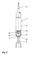
- the damping element 1 shown consists essentially of the container tube 3, the piston rod 2 and the fastening part 5.
- the fastening part 5 is connected to a bottom 4, wherein between the bottom 4 and the fastening part 5, a contact surface 12 is formed, wherein the fastening part 5 with the ground 4 as well as the bottom 4 with the container tube 3 are welded together via a weld seam 7.
- a damping element 1 can be seen, which consists of a piston rod 2, a one-piece container tube 6 and the fastening part 5.
- a compensation chamber 8 Within the container tube 6 is a compensation chamber 8, a working space 9 and a piston 10 can be seen.
- the working space 9 is formed by a corresponding cylinder tube 11.
- the one-piece container tube 6 is connected at its end to the fastening part 5, which in turn results in a contact surface 12 and at this point a weld seam 7 is provided for a connection between the one-piece container tube and the fastening part 5.
- FIG. 3 shows in principle a damping element 1 as in FIG. 2 already shown, with the difference that the fastening part 5 is received in a bore of the one-piece container tube 6 and thereby a joining surface 13 is formed, so that between the bottom of the one-piece container tube 6 and the outer periphery of the shank of the fastening part 5 a connection via a weld 7 is made.
- FIG. 4 Another embodiment of a damping element 1 is shown in FIG. 4 can be seen, wherein between the container tube 3 and the fastening part 5, a bottom 4 is provided, while the bottom 4 has a bore, as in FIG. 3 is already shown, so that the resulting joining surface 13 is used to connect both the fastening part 5 with the bottom 4 as well as the bottom 4 with the container tube 3 via a respective weld 7.
- a damping element 1 can be seen with a container tube 3, wherein provided for closing the container tube 3 bottom 4 is provided with a cup 14, in which the shank of the fastening part 5 is added. It is again the fastening part 5 with the bottom 4 and the bottom 4 with the container tube 3 via one weld 7 firmly connected.
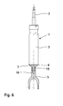
- FIG. 6 shows a damping element 1, wherein the container tube 3 is closed by a bottom 4, the bottom 4 is provided with a pin 15 which is received in a bore 16 of the fastening part 5.
- the connection between the pin 15 and the fastening part 5 takes place in this case via a threaded connection, but there are also connections such as pressing, gluing, welding, joining, caulking or soldering readily possible.
- the bottom 4 together with the fastening part 5 is firmly connected to the container tube 3 via the weld 7.
- FIGS. 7 to 7a From the FIGS. 7 to 7a is a fixing member 5 can be seen in which the fork 19 are provided with mounting holes 20 for connection of the damping element to a vehicle, while the integrally provided with the fork 19 shaft 17 is formed in its cross-section oval.
- the Figure 7a shows this in top view.
- FIGS. 8 and 8a a fastening part 5 can be seen, in which the fork 19 is also formed integrally with the shaft 18, while the shaft 18 has a round cross-section, as shown in FIG. 8a can be seen.
Landscapes
- Engineering & Computer Science (AREA)
- General Engineering & Computer Science (AREA)
- Mechanical Engineering (AREA)
- Fluid-Damping Devices (AREA)
- Connection Of Plates (AREA)
- Prostheses (AREA)
- Orthopedics, Nursing, And Contraception (AREA)
Description
- Die Erfindung betrifft ein Dämpfungselement zwischen zwei Massen, bestehend aus ein Behälterrohr, einem darin in einem Dämpfungsmedium verschiebbar angeordneten Kolben, einer mit diesem verbundenen Kolbenstange und einem Befestigungsteil zur Verbindung des Dämpfungselements mit einer ersten der beiden gegeneinander schwingungsarm zu haltenden Massen, wobei die Kolbenstange mit einer der Massen verbunden ist.
- Dämpfungselemente der vorgenannten Art (z.B.
DE 102 08 560 A1 ) werden beispielsweise an Fahrzeugen zwischen einer ersten Masse, nämlich der von Schwingungen frei zu haltenden Fahrgastzelle und einer zweiten Masse, nämlich den beim Fahrbetrieb unter Schwingungen stehenden Rädern eingesetzt. Dabei ist das Dämpfungselement mittels einer Kolbenstange mit beispielsweise der ersten Masse und mit einem Befestigungsteil mit der zweiten Masse verbunden, wobei die Kolbenstange an einem Kolben angelenkt ist, der in einem mit dem Befestigungsteil verbundenen und mit einem Dämpfungsmedium gefüllten Behälterrohr des Dämpfungselements entsprechend den relativen Schwingungsbewegungen der beiden Massen zueinander oszillierende Bewegungen ausführt. - Bei bestimmten Ausführungsformen ist das Befestigungsteil am Dämpfungselement für eine schwenkbare Befestigung an der zweiten Masse mit einer Gabel ausgestaltet, die an ihren beiden Enden Bohrungen aufweist, um das Dämpfungselement mittels eines durchgeschobenen Bolzens an der zweiten Masse gelenkig zu lagern. Gemäß dem Stand der Technik ist diese Gabel an einem Schaft und dieser wiederum an einem Boden des Behälterrohres angeordnet, wobei dieser Boden eine Scheibe ist, die mit dem Behälterrohr verschweißt ist, um diese abzudichten. Diese Scheibe wird also mit dem Schaft und dieser mit der Gabel verschweißt, um die Funktionen "Abdichten" und "Befestigen" zu sichern.
- Der Erfindungsgegenstand der vorliegenden Erfindung sieht vor, die zwei Teile, nämlich den Schaft und die Gabel in einem einzigen Teil zu vereinigen, um ein Herstellungsverfahren zu ermöglichen, welches kostengünstig, aber vor allem für eine Großserienfertigung geeignet ist und anschließend mit dem Boden zu verbinden. Des weiteren wird eine erhöhte Festigkeit des Bauteils erzielt. Die Vorteile dieser Maßnahme liegen auf der Hand: Das Befestigungsteil wird als Schmiedeteil vorgesehen, weil es dadurch die spanende Bearbeitung auf ein Minimum reduziert. Das Gewicht des Befestigungsteils kann reduziert werden, wenn es in seinen Abmessungen den Knick - und Biegeanforderungen angepasst wird. Besonderes Augenmerk ist hier auf den Schaft zu legen, dessen Querschnitt ein Profil aufweisen kann, das beispielsweise ein Doppel-T-Profil ist, welches dem Herstellungsverfahren "Schmieden" keine Schwierigkeiten entgegensetzt.
- Die vorliegende Erfindung hat es sich daher zur Aufgabe gemacht, ein Dämpfungselement, bestehend aus einem Behälterrohr, einem darin verschiebbar angeordneten Kolben, einer mit diesem verbundenen Kolbenstange und einem Befestigungsteil auf kostengünstige Weise und mit geringem Montageaufwand durch eine Rationalisierung des Befestigungsteils her zu stellen.
- Die Lösung der Aufgabe ist im Kennzeichen des Hauptanspruches beschrieben. Ausgestaltungen sind den Unteransprüchen zu entnehmen.
- Anhand mehrerer Zeichnungen wird ein Ausführungsbeispiel eines Befestigungsteils und dessen Anordnung an einem Behälterrohr eines Dämpfungselements erläutert.
- Es zeigen:
-
Figur 1 ein Dämpfungselement, bestehend aus einem Behälterrohr, einer Kolbenstange und einem Befestigungsteil, teils im Schnitt -
Figur 2 eine weitere Darstellung des inFigur 1 dargestellten Dämpfungselementes, wobei das Behälterrohr teils geschnitten ist -
Figur 3 eine weitere Ausführungsform eines Dämpfungselementes, teils im Schnitt -
Figur 4 ein Dämpfungselement, teils im Schnitt -
Figur 5 eine weitere Ausführungsform des Befestigungsteils und dessen Anbindung an ein Behälterrohr -
Figur 6 eine nicht erfindungsgemäß verschraubte Version eines Befestigungsteiles an einem Boden -
Figur 7 und 8 zwei verschiedene Ausführungsformen eines Befestigungsteiles. - Das in
Figur 1 dargestellte Dämpfungselement 1 besteht im wesentlichen aus dem Behälterrohr 3, der Kolbenstange 2 sowie dem Befestigungsteil 5. Das Befestigungsteil 5 ist mit einem Boden 4 verbunden, wobei zwischen dem Boden 4 und dem Befestigungsteil 5 eine Kontaktfläche 12 entsteht, wobei das Befestigungsteil 5 mit dem Boden 4 sowie auch der Boden 4 mit dem Behälterrohr 3 über eine Schweißnaht 7 miteinander verschweißt sind. - Aus der
Figur 2 ist wiederum ein Dämpfungselement 1 zu entnehmen, welches aus einer Kolbenstange 2, einem einteiligen Behälterrohr 6 und dem Befestigungsteil 5 besteht. Innerhalb des Behälterrohres 6 ist ein Ausgleichsraum 8, ein Arbeitsraum 9 sowie ein Kolben 10 zu erkennen. Der Arbeitsraum 9 wird durch ein entsprechendes Zylinderrohr 11 gebildet. Das einteilige Behälterrohr 6 ist an seinem Ende mit dem Befestigungsteil 5 verbunden, wobei sich wiederum eine Kontaktfläche 12 ergibt und an dieser Stelle eine Schweißnaht 7 für eine Verbindung zwischen dem einteiligen Behälterrohr und dem Befestigungsteil 5 vorgesehen ist. - Die
Figur 3 zeigt im Prinzip ein Dämpfungselement 1 wie es inFigur 2 bereits dargestellt ist, mit dem Unterschied, dass das Befestigungsteil 5 in einer Bohrung des einteiligen Behälterrohres 6 aufgenommen ist und dabei eine Fügefläche 13 entsteht, so dass zwischen dem Boden des einteiligen Behälterrohres 6 und dem Außenumfang des Schaftes des Befestigungsteiles 5 eine Verbindung über eine Schweißnaht 7 hergestellt wird. - Eine weitere Ausführungsform eines Dämpfungselementes 1 ist in
Figur 4 zu entnehmen, wobei zwischen dem Behälterrohr 3 und dem Befestigungsteil 5 ein Boden 4 vorgesehen ist, dabei besitzt der Boden 4 eine Bohrung, wie sie inFigur 3 bereits dargestellt ist, so dass die entstehende Fügefläche 13 herangezogen wird, um sowohl das Befestigungsteil 5 mit dem Boden 4 wie auch der Boden 4 mit dem Behälterrohr 3 über jeweils eine Schweißnaht 7 miteinander verbunden wird. - Aus der
Figur 5 ist ein Dämpfungselement 1 mit einem Behälterrohr 3 zu entnehmen, wobei der zum Verschließen des Behälterrohres 3 vorgesehene Boden 4 mit einem Napf 14 versehen ist, in den der Schaft des Befestigungsteiles 5 aufgenommen ist. Es wird wiederum das Befestigungsteil 5 mit dem Boden 4 sowie der Boden 4 mit dem Behälterrohr 3 über jeweils eine Schweißnaht 7 fest miteinander verbunden. - Die
Figur 6 zeigt ein Dämpfungselement 1, wobei das Behälterrohr 3 über einen Boden 4 verschlossen wird, der Boden 4 ist dabei mit einem Zapfen 15 versehen, welcher in einer Bohrung 16 des Befestigungsteiles 5 aufgenommen ist. Die Verbindung zwischen dem Zapfen 15 und dem Befestigungsteil 5 erfolgt in diesem Falle über eine Gewindeverbindung, es sind jedoch ebenfalls Verbindungen wie Pressen, Kleben, Schweißen, Fügen, Verstemmen oder Löten ohne weiteres möglich. Der Boden 4 zusammen mit dem Befestigungsteil 5 wird mit dem Behälterrohr 3 über die Schweißnaht 7 fest verbunden. - Aus den
Figuren 7 bis 7a ist ein Befestigungsteil 5 zu entnehmen, bei dem die Gabel 19 mit Befestigungsbohrungen 20 zur Anbindung des Dämpfungselementes an ein Fahrzeug versehen sind, dabei ist der einteilig mit der Gabel 19 versehene Schaft 17 in seinem Querschnitt oval ausgebildet. DieFigur 7a zeigt dieses in Draufsicht. - Aus den
Figuren 8 und 8a ist wiederum ein Befestigungsteil 5 zu entnehmen, bei dem die Gabel 19 ebenfalls einteilig mit dem Schaft 18 ausgebildet ist, dabei besitzt der Schaft 18 einen runden Querschnitt, wie dies aus derFigur 8a zu entnehmen ist. -
- 1 -
- Dämpfungselement
- 2 -
- Kolbenstange
- 3 -
- Behälterrohr
- 4 -
- Boden
- 5 -
- Befestigungsteil
- 6 -
- Behälterrohr einteilig
- 7 -
- Schweißnaht
- 8 -
- Ausgleichsraum
- 9 -
- Arbeitsraum
- 10 -
- Kolben
- 11 -
- Zylinderrohr
- 12 -
- Kontaktfläche
- 13 -
- Fügefläche
- 14 -
- Napf
- 15 -
- Zapfen
- 16 -
- Bohrung
- 17 -
- Schaft oval
- 18 -
- Schaft rund
- 19 -
- Gabel
- 20 -
- Befestigungsbohrung
Claims (5)
- Dämpfungselement zwischen zwei Massen, bestehend aus ein Behälterrohr, einem darin in einem Dämpfungsmedium verschiebbar angeordneten Kolben, einer mit diesem verbundenen Kolbenstange und einem Befestigungsteil zur Verbindung des Dämpfungselements mit einer ersten der beiden gegeneinander schwingungsarm zu haltenden Massen, wobei die Kolbenstange mit der zweiten Masse und das Befestigungsteil mit der ersten Masse verbunden ist,
dadurch gekennzeichnet,
dass das Befestigungsteil (5) einteilig und als Schmiedeteil ausgebildet ist und ausschließend aus einem Schaft (17, 18) und einer Gabel (19) besteht und mit dem Boden des Behälterrohres (3) verschweißt ist. - Dämpfungselement nach Anspruch 1,
dadurch gekennzeichnet,
dass das Befestigungsteil (5) aus Stahl besteht. - Dämpfungselement nach Anspruch 1,
dadurch gekennzeichnet,
dass der Schaft (17, 18) zur Erhöhung des Widerstandsmoments, zur Gewichtseinsparung, zum Längenausgleich und/oder zur Schaffung eines Freiraumes ein Profil aufweist. - Dämpfungselement nach Anspruch 1,
dadurch gekennzeichnet,
dass das Behälterrohr (3) auf einem Zentrieransatz mit vorzugsweise einem Anschlag an dem Boden (4) zentriert ist. - Schwingungsdämpfer nach einem der vorhergehenden Ansprüche,
dadurch gekennzeichnet,
dass die Verbindungsstelle zwischen dem Befestigungsteil und dem Bodem des Behälterrohres eine Pressverbindung ist, die anschließend gesichert wird.
Applications Claiming Priority (2)
| Application Number | Priority Date | Filing Date | Title |
|---|---|---|---|
| DE102004001933A DE102004001933A1 (de) | 2004-01-14 | 2004-01-14 | Befestigungselement mit multifunktionalem Befestigungsteil |
| DE102004001933 | 2004-01-14 |
Publications (2)
| Publication Number | Publication Date |
|---|---|
| EP1555454A1 EP1555454A1 (de) | 2005-07-20 |
| EP1555454B1 true EP1555454B1 (de) | 2010-04-14 |
Family
ID=34609537
Family Applications (1)
| Application Number | Title | Priority Date | Filing Date |
|---|---|---|---|
| EP04026370A Expired - Lifetime EP1555454B1 (de) | 2004-01-14 | 2004-11-05 | Befestigungselement mit multifunktionalem Befestigungsteil |
Country Status (4)
| Country | Link |
|---|---|
| EP (1) | EP1555454B1 (de) |
| AT (1) | ATE464491T1 (de) |
| DE (2) | DE102004001933A1 (de) |
| ES (1) | ES2342167T3 (de) |
Families Citing this family (6)
| Publication number | Priority date | Publication date | Assignee | Title |
|---|---|---|---|---|
| DE102006016701B4 (de) * | 2006-04-08 | 2012-06-14 | Zf Friedrichshafen Ag | Kolben-Zylinder-Aggregat |
| DE102006042801A1 (de) * | 2006-09-08 | 2008-03-27 | Zf Friedrichshafen Ag | Dämpfungselement |
| DE102007005197B4 (de) | 2007-01-29 | 2015-07-02 | Zf Friedrichshafen Ag | Dämpfelement |
| US8006993B1 (en) | 2010-05-14 | 2011-08-30 | Specialized Bicycle Components, Inc. | Bicycle frame |
| DE102013209328B3 (de) * | 2013-05-21 | 2014-10-23 | Zf Friedrichshafen Ag | Kolben-Zylinder-Aggregat |
| DE202022000912U1 (de) | 2022-04-11 | 2023-07-13 | Bümach Engineering International B.V. | Arbeitszylinder |
Citations (1)
| Publication number | Priority date | Publication date | Assignee | Title |
|---|---|---|---|---|
| US4740100A (en) * | 1986-05-20 | 1988-04-26 | Valmet Oy | Attachment lug adapted to be fixed to an end of a cylindrical body, such as a power cylinder, and assembly |
Family Cites Families (3)
| Publication number | Priority date | Publication date | Assignee | Title |
|---|---|---|---|---|
| JPH0666343A (ja) * | 1992-08-20 | 1994-03-08 | Tokico Ltd | シリンダ装置用取付ブラケットの製造方法 |
| JP4018195B2 (ja) * | 1997-06-13 | 2007-12-05 | 株式会社ショーワ | ストラットダンパのマウントジョイント部固定構造 |
| DE10208560B4 (de) * | 2002-02-27 | 2006-01-19 | Zf Sachs Ag | Befestigungselement mit multifunktionalem Befestigungsteil |
-
2004
- 2004-01-14 DE DE102004001933A patent/DE102004001933A1/de not_active Ceased
- 2004-11-05 DE DE502004011029T patent/DE502004011029D1/de not_active Expired - Lifetime
- 2004-11-05 ES ES04026370T patent/ES2342167T3/es not_active Expired - Lifetime
- 2004-11-05 AT AT04026370T patent/ATE464491T1/de not_active IP Right Cessation
- 2004-11-05 EP EP04026370A patent/EP1555454B1/de not_active Expired - Lifetime
Patent Citations (1)
| Publication number | Priority date | Publication date | Assignee | Title |
|---|---|---|---|---|
| US4740100A (en) * | 1986-05-20 | 1988-04-26 | Valmet Oy | Attachment lug adapted to be fixed to an end of a cylindrical body, such as a power cylinder, and assembly |
Also Published As
| Publication number | Publication date |
|---|---|
| EP1555454A1 (de) | 2005-07-20 |
| ATE464491T1 (de) | 2010-04-15 |
| ES2342167T3 (es) | 2010-07-02 |
| DE102004001933A1 (de) | 2005-08-11 |
| DE502004011029D1 (de) | 2010-05-27 |
Similar Documents
| Publication | Publication Date | Title |
|---|---|---|
| DE10208560B4 (de) | Befestigungselement mit multifunktionalem Befestigungsteil | |
| EP2902303B1 (de) | Hilfsrahmen für ein Kraftfahrzeug, insbesondere Vorderachs-Hilfsrahmen, und Karosserie mit einem solchen Hilfsrahmen | |
| EP1698797B1 (de) | Schwingungsdämpfer mit amplitudenabhängiger Dämpfung | |
| DE102009029299B4 (de) | Schwingungsdämpfer | |
| DE112017005369B4 (de) | Fahrzeugrahmen-stützapparat | |
| DE10351353B4 (de) | Schwingungsdämpfer mit amplitudenabhängiger Dämpfung | |
| DE2338957C3 (de) | Vorrichtung zum Befestigen eines Schutzdaches o.dgl. am Rahmen eines Erdbewegungs- o.ä. Fahrzeugs | |
| EP2195549B1 (de) | Geberzylinder, insbesondere für die kupplungs- oder bremsbetätigung eines kraftfahrzeuges | |
| WO2011113514A1 (de) | Radträger für eine mehrlenker - einzelradaufhängung | |
| EP1526302A1 (de) | Dämpfungselement | |
| DE10310226A1 (de) | Schlepphebel eines Ventiltriebs einer Brennkraftmaschine | |
| EP1555454B1 (de) | Befestigungselement mit multifunktionalem Befestigungsteil | |
| DE4445251A1 (de) | Befestigungsanordnung zwischen einem Innenteil und einem Außenteil | |
| DE102007041382B4 (de) | Reserveradmulde für ein Kraftfahrzeug | |
| DE102018216992B4 (de) | Luftfederbein mit Verstärkungseinsatz im Deckel | |
| DE102009028458B4 (de) | Modulares Lenkerelement | |
| DE102012017319B4 (de) | Befestigungsanordnung zwischen einem Radiallager und einem Stützarm | |
| DE102005007613A1 (de) | Gedämpftes Kugelgelenk | |
| EP1898120B1 (de) | Dämpfungselement | |
| DE102006032511A1 (de) | Elastisches Fahrwerkslager | |
| EP3988352A1 (de) | Verbundlenker für ein fahrwerk eines kraftfahrzeugs | |
| DE102019105712A1 (de) | Verbindungskomponente in der Karosserie oder im Fahrwerksbereich eines Kraftfahrzeugs | |
| DE20214356U1 (de) | Verbindung zwischen einer Scheibe und einer Stange | |
| DE102014223632A1 (de) | Hinterachse eines Kraftfahrzeugs sowie Kraftfahrzeug mit einer derartigen Hinterachse | |
| EP1950450A1 (de) | Dämpfelement |
Legal Events
| Date | Code | Title | Description |
|---|---|---|---|
| PUAI | Public reference made under article 153(3) epc to a published international application that has entered the european phase |
Free format text: ORIGINAL CODE: 0009012 |
|
| AK | Designated contracting states |
Kind code of ref document: A1 Designated state(s): AT BE BG CH CY CZ DE DK EE ES FI FR GB GR HU IE IS IT LI LU MC NL PL PT RO SE SI SK TR |
|
| AX | Request for extension of the european patent |
Extension state: AL HR LT LV MK YU |
|
| 17P | Request for examination filed |
Effective date: 20051001 |
|
| AKX | Designation fees paid |
Designated state(s): AT BE BG CH CY CZ DE DK EE ES FI FR GB GR HU IE IS IT LI LU MC NL PL PT RO SE SI SK TR |
|
| 17Q | First examination report despatched |
Effective date: 20051202 |
|
| GRAP | Despatch of communication of intention to grant a patent |
Free format text: ORIGINAL CODE: EPIDOSNIGR1 |
|
| GRAS | Grant fee paid |
Free format text: ORIGINAL CODE: EPIDOSNIGR3 |
|
| GRAA | (expected) grant |
Free format text: ORIGINAL CODE: 0009210 |
|
| AK | Designated contracting states |
Kind code of ref document: B1 Designated state(s): AT BE BG CH CY CZ DE DK EE ES FI FR GB GR HU IE IS IT LI LU MC NL PL PT RO SE SI SK TR |
|
| REG | Reference to a national code |
Ref country code: GB Ref legal event code: FG4D Free format text: NOT ENGLISH |
|
| REG | Reference to a national code |
Ref country code: CH Ref legal event code: EP |
|
| REG | Reference to a national code |
Ref country code: IE Ref legal event code: FG4D Free format text: LANGUAGE OF EP DOCUMENT: GERMAN |
|
| REF | Corresponds to: |
Ref document number: 502004011029 Country of ref document: DE Date of ref document: 20100527 Kind code of ref document: P |
|
| REG | Reference to a national code |
Ref country code: ES Ref legal event code: FG2A Ref document number: 2342167 Country of ref document: ES Kind code of ref document: T3 |
|
| REG | Reference to a national code |
Ref country code: NL Ref legal event code: VDEP Effective date: 20100414 |
|
| PG25 | Lapsed in a contracting state [announced via postgrant information from national office to epo] |
Ref country code: SE Free format text: LAPSE BECAUSE OF FAILURE TO SUBMIT A TRANSLATION OF THE DESCRIPTION OR TO PAY THE FEE WITHIN THE PRESCRIBED TIME-LIMIT Effective date: 20100414 Ref country code: NL Free format text: LAPSE BECAUSE OF FAILURE TO SUBMIT A TRANSLATION OF THE DESCRIPTION OR TO PAY THE FEE WITHIN THE PRESCRIBED TIME-LIMIT Effective date: 20100414 |
|
| REG | Reference to a national code |
Ref country code: IE Ref legal event code: FD4D |
|
| PG25 | Lapsed in a contracting state [announced via postgrant information from national office to epo] |
Ref country code: SI Free format text: LAPSE BECAUSE OF FAILURE TO SUBMIT A TRANSLATION OF THE DESCRIPTION OR TO PAY THE FEE WITHIN THE PRESCRIBED TIME-LIMIT Effective date: 20100414 Ref country code: IS Free format text: LAPSE BECAUSE OF FAILURE TO SUBMIT A TRANSLATION OF THE DESCRIPTION OR TO PAY THE FEE WITHIN THE PRESCRIBED TIME-LIMIT Effective date: 20100814 Ref country code: FI Free format text: LAPSE BECAUSE OF FAILURE TO SUBMIT A TRANSLATION OF THE DESCRIPTION OR TO PAY THE FEE WITHIN THE PRESCRIBED TIME-LIMIT Effective date: 20100414 |
|
| PG25 | Lapsed in a contracting state [announced via postgrant information from national office to epo] |
Ref country code: PL Free format text: LAPSE BECAUSE OF FAILURE TO SUBMIT A TRANSLATION OF THE DESCRIPTION OR TO PAY THE FEE WITHIN THE PRESCRIBED TIME-LIMIT Effective date: 20100414 Ref country code: CY Free format text: LAPSE BECAUSE OF FAILURE TO SUBMIT A TRANSLATION OF THE DESCRIPTION OR TO PAY THE FEE WITHIN THE PRESCRIBED TIME-LIMIT Effective date: 20100421 Ref country code: GR Free format text: LAPSE BECAUSE OF FAILURE TO SUBMIT A TRANSLATION OF THE DESCRIPTION OR TO PAY THE FEE WITHIN THE PRESCRIBED TIME-LIMIT Effective date: 20100715 |
|
| PG25 | Lapsed in a contracting state [announced via postgrant information from national office to epo] |
Ref country code: EE Free format text: LAPSE BECAUSE OF FAILURE TO SUBMIT A TRANSLATION OF THE DESCRIPTION OR TO PAY THE FEE WITHIN THE PRESCRIBED TIME-LIMIT Effective date: 20100414 Ref country code: PT Free format text: LAPSE BECAUSE OF FAILURE TO SUBMIT A TRANSLATION OF THE DESCRIPTION OR TO PAY THE FEE WITHIN THE PRESCRIBED TIME-LIMIT Effective date: 20100816 Ref country code: DK Free format text: LAPSE BECAUSE OF FAILURE TO SUBMIT A TRANSLATION OF THE DESCRIPTION OR TO PAY THE FEE WITHIN THE PRESCRIBED TIME-LIMIT Effective date: 20100414 Ref country code: IE Free format text: LAPSE BECAUSE OF FAILURE TO SUBMIT A TRANSLATION OF THE DESCRIPTION OR TO PAY THE FEE WITHIN THE PRESCRIBED TIME-LIMIT Effective date: 20100414 |
|
| PLBE | No opposition filed within time limit |
Free format text: ORIGINAL CODE: 0009261 |
|
| STAA | Information on the status of an ep patent application or granted ep patent |
Free format text: STATUS: NO OPPOSITION FILED WITHIN TIME LIMIT |
|
| PG25 | Lapsed in a contracting state [announced via postgrant information from national office to epo] |
Ref country code: RO Free format text: LAPSE BECAUSE OF FAILURE TO SUBMIT A TRANSLATION OF THE DESCRIPTION OR TO PAY THE FEE WITHIN THE PRESCRIBED TIME-LIMIT Effective date: 20100414 Ref country code: CZ Free format text: LAPSE BECAUSE OF FAILURE TO SUBMIT A TRANSLATION OF THE DESCRIPTION OR TO PAY THE FEE WITHIN THE PRESCRIBED TIME-LIMIT Effective date: 20100414 Ref country code: SK Free format text: LAPSE BECAUSE OF FAILURE TO SUBMIT A TRANSLATION OF THE DESCRIPTION OR TO PAY THE FEE WITHIN THE PRESCRIBED TIME-LIMIT Effective date: 20100414 |
|
| 26N | No opposition filed |
Effective date: 20110117 |
|
| PGFP | Annual fee paid to national office [announced via postgrant information from national office to epo] |
Ref country code: IT Payment date: 20101113 Year of fee payment: 7 |
|
| PG25 | Lapsed in a contracting state [announced via postgrant information from national office to epo] |
Ref country code: MC Free format text: LAPSE BECAUSE OF NON-PAYMENT OF DUE FEES Effective date: 20101130 |
|
| REG | Reference to a national code |
Ref country code: CH Ref legal event code: PL |
|
| GBPC | Gb: european patent ceased through non-payment of renewal fee |
Effective date: 20101105 |
|
| PG25 | Lapsed in a contracting state [announced via postgrant information from national office to epo] |
Ref country code: CH Free format text: LAPSE BECAUSE OF NON-PAYMENT OF DUE FEES Effective date: 20101130 Ref country code: LI Free format text: LAPSE BECAUSE OF NON-PAYMENT OF DUE FEES Effective date: 20101130 |
|
| PG25 | Lapsed in a contracting state [announced via postgrant information from national office to epo] |
Ref country code: GB Free format text: LAPSE BECAUSE OF NON-PAYMENT OF DUE FEES Effective date: 20101105 |
|
| PGFP | Annual fee paid to national office [announced via postgrant information from national office to epo] |
Ref country code: ES Payment date: 20111216 Year of fee payment: 8 |
|
| REG | Reference to a national code |
Ref country code: AT Ref legal event code: MM01 Ref document number: 464491 Country of ref document: AT Kind code of ref document: T Effective date: 20101105 |
|
| PG25 | Lapsed in a contracting state [announced via postgrant information from national office to epo] |
Ref country code: AT Free format text: LAPSE BECAUSE OF NON-PAYMENT OF DUE FEES Effective date: 20101105 |
|
| PGFP | Annual fee paid to national office [announced via postgrant information from national office to epo] |
Ref country code: BE Payment date: 20111114 Year of fee payment: 8 |
|
| PG25 | Lapsed in a contracting state [announced via postgrant information from national office to epo] |
Ref country code: HU Free format text: LAPSE BECAUSE OF FAILURE TO SUBMIT A TRANSLATION OF THE DESCRIPTION OR TO PAY THE FEE WITHIN THE PRESCRIBED TIME-LIMIT Effective date: 20101015 Ref country code: LU Free format text: LAPSE BECAUSE OF NON-PAYMENT OF DUE FEES Effective date: 20101105 Ref country code: BG Free format text: LAPSE BECAUSE OF FAILURE TO SUBMIT A TRANSLATION OF THE DESCRIPTION OR TO PAY THE FEE WITHIN THE PRESCRIBED TIME-LIMIT Effective date: 20100414 |
|
| PG25 | Lapsed in a contracting state [announced via postgrant information from national office to epo] |
Ref country code: TR Free format text: LAPSE BECAUSE OF FAILURE TO SUBMIT A TRANSLATION OF THE DESCRIPTION OR TO PAY THE FEE WITHIN THE PRESCRIBED TIME-LIMIT Effective date: 20100414 |
|
| BERE | Be: lapsed |
Owner name: ZF FRIEDRICHSHAFEN A.G. Effective date: 20121130 |
|
| PG25 | Lapsed in a contracting state [announced via postgrant information from national office to epo] |
Ref country code: IT Free format text: LAPSE BECAUSE OF NON-PAYMENT OF DUE FEES Effective date: 20121105 Ref country code: BE Free format text: LAPSE BECAUSE OF NON-PAYMENT OF DUE FEES Effective date: 20121130 |
|
| PG25 | Lapsed in a contracting state [announced via postgrant information from national office to epo] |
Ref country code: BG Free format text: LAPSE BECAUSE OF FAILURE TO SUBMIT A TRANSLATION OF THE DESCRIPTION OR TO PAY THE FEE WITHIN THE PRESCRIBED TIME-LIMIT Effective date: 20100714 |
|
| PGFP | Annual fee paid to national office [announced via postgrant information from national office to epo] |
Ref country code: FR Payment date: 20131108 Year of fee payment: 10 |
|
| REG | Reference to a national code |
Ref country code: ES Ref legal event code: FD2A Effective date: 20140305 |
|
| PG25 | Lapsed in a contracting state [announced via postgrant information from national office to epo] |
Ref country code: ES Free format text: LAPSE BECAUSE OF NON-PAYMENT OF DUE FEES Effective date: 20121106 |
|
| PGFP | Annual fee paid to national office [announced via postgrant information from national office to epo] |
Ref country code: DE Payment date: 20141029 Year of fee payment: 11 |
|
| REG | Reference to a national code |
Ref country code: FR Ref legal event code: ST Effective date: 20150731 |
|
| PG25 | Lapsed in a contracting state [announced via postgrant information from national office to epo] |
Ref country code: FR Free format text: LAPSE BECAUSE OF NON-PAYMENT OF DUE FEES Effective date: 20141201 |
|
| REG | Reference to a national code |
Ref country code: DE Ref legal event code: R119 Ref document number: 502004011029 Country of ref document: DE |
|
| PG25 | Lapsed in a contracting state [announced via postgrant information from national office to epo] |
Ref country code: DE Free format text: LAPSE BECAUSE OF NON-PAYMENT OF DUE FEES Effective date: 20160601 |