EP1555377A2 - Mounting and spacer device - Google Patents
Mounting and spacer device Download PDFInfo
- Publication number
- EP1555377A2 EP1555377A2 EP04030766A EP04030766A EP1555377A2 EP 1555377 A2 EP1555377 A2 EP 1555377A2 EP 04030766 A EP04030766 A EP 04030766A EP 04030766 A EP04030766 A EP 04030766A EP 1555377 A2 EP1555377 A2 EP 1555377A2
- Authority
- EP
- European Patent Office
- Prior art keywords
- carrying
- padding device
- bearing
- glass carrier
- glazing
- Prior art date
- Legal status (The legal status is an assumption and is not a legal conclusion. Google has not performed a legal analysis and makes no representation as to the accuracy of the status listed.)
- Withdrawn
Links
Images

Classifications
-
- E—FIXED CONSTRUCTIONS
- E04—BUILDING
- E04B—GENERAL BUILDING CONSTRUCTIONS; WALLS, e.g. PARTITIONS; ROOFS; FLOORS; CEILINGS; INSULATION OR OTHER PROTECTION OF BUILDINGS
- E04B2/00—Walls, e.g. partitions, for buildings; Wall construction with regard to insulation; Connections specially adapted to walls
- E04B2/88—Curtain walls
- E04B2/96—Curtain walls comprising panels attached to the structure through mullions or transoms
- E04B2/967—Details of the cross-section of the mullions or transoms
-
- E—FIXED CONSTRUCTIONS
- E06—DOORS, WINDOWS, SHUTTERS, OR ROLLER BLINDS IN GENERAL; LADDERS
- E06B—FIXED OR MOVABLE CLOSURES FOR OPENINGS IN BUILDINGS, VEHICLES, FENCES OR LIKE ENCLOSURES IN GENERAL, e.g. DOORS, WINDOWS, BLINDS, GATES
- E06B3/00—Window sashes, door leaves, or like elements for closing wall or like openings; Layout of fixed or moving closures, e.g. windows in wall or like openings; Features of rigidly-mounted outer frames relating to the mounting of wing frames
- E06B3/54—Fixing of glass panes or like plates
- E06B3/5409—Means for locally spacing the pane from the surrounding frame
Definitions
- the invention relates to a carrying and padding device according to the preamble of Claim 1.
- Such a carrying and padding device is known from DE 76 28 717 U.
- a carrying and padding device which is a block having a flat surface facing the edge of the glass and on the opposite side in the transition region to the frame of a window, a door or a facade provided with a directly adjacent to the frame profile concave surface is.
- Such a rocker is designed to ensure that the surface elements always be supported evenly on the blocks. In this way it is possible Tolerance differences in the border area to compensate and the Krafterresultierende evenly at a lying between the two outer edges of the surface elements Place in the frame.
- a further problem is that according to the prior art, the blocks loosely under the Surface elements are positioned so that it is easy to move and to Assembly problems can come.
- the wear and Blocking device for surface elements to develop such that a particularly high load capacity and a compensation of tolerances of the surface element is possible.
- an easy and safe installation should be ensured.
- the carrying and padding device has a multi-part design with a glass carrier and a glazing bridge on which rocker and / or interact in a bearing-like manner to align the insulating glass pane and the frame profile compensate.
- a carrying and padding device which is simple can be mounted and thereby fixed captive on the frame profile. Furthermore, a warehouse provided that is able to remove particularly high loads without the Disadvantages of the prior art occur, after which the introduction of force through the on A concave approach rolling off a flat surface always takes place at a different location.
- the glass carrier is preferably fixed in the glazing rebate, in particular in a screw groove the frame profile, in particular a latch profile of a facade.
- the glass carrier has on its surface element turned side on a bearing recess or a bearing neck on, with a corresponding shaped bearing lug or a correspondingly shaped bearing recess cooperates on the glazing bridge and so the rocker and camp-like arrangement forms.
- the bearing recess are concave and the bearing projection convex shaped (e.g., approximately semi-cylindrical). This variant is easy to manufacture and build very compact.
- the bearing recess as a hemispherical or oval or barrel-like cup and the bearing shoulder as a corresponding cup-like, In particular hemispherical or oval or barrel-like projection is formed, in the corresponding dome-shaped, in particular hemispherical or oval or barrel-like bearing recess engages.
- a tolerance compensation becomes easy ensured in several directions, the force is always at the defined Guaranteed place and a defined fixing of the disc also perpendicular to Level of Fig.1 realized.
- a pivot bearing with a bearing pin formed in at least one corresponding Bearing recess engages the corre sponding component is between the glass carrier and the glazing bridge a pivot bearing with a bearing pin formed in at least one corresponding Bearing recess engages the corre sponding component.
- the glass carrier as a stable and lighter metal profile section is formed, which has a hollow chamber.
- At least one support leg or several support feet molded onto the glass carrier which support the glass carrier on Frame profile are designed, in particular such that the at least one support leg supported on the bolt profile between the screw groove and the sealing grooves.
- the glass carrier and The glazing bridge is an easy-to-handle, preassembled unit. That's it advantageous if the glass carrier and the glazing bridge by means of a (detent) dowel connected to each other.
- the dowel can be designed as a dowel base, which is formed on one of the components of the carrying and padding device.
- the dowel foot is expediently integrally formed on the glazing bridge or spacer block and passes through the other components of the carrying and padding device.
- the glass carrier and the glazing bridge to each other via a dowel base connected either directly to the glazing bridge by means of a separate Dowel or is formed on a spacer block and to engage in the corresponding Element glazing bridge or glass carrier is designed.
- Pre-assembly ensures that, despite the possibility of tolerance compensation the installation of the disc against a use of simple block pieces not is difficult.
- the tolerance compensation is done almost “automatically” without that the installer must take special measures.
- the glass carrier and / or the glazing bridge as a light metal profile formed and the glazing bridge exists at least in their the surface element facing area of plastic or is made with a plastic spacer provided to protect the surface element.
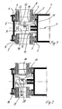
- FIG. 1 shows a section through a first transom-post construction of a facade in the region of the bar profile 1 shown here only partially.
- undercut Grooves 2 arranged in the plant seals 3 are used, which are to invest an insulating glass 8 serve.
- Holding profile 5 On the bolt profile 1 opposite side of the insulating glass 8 is a Holding profile 5 is arranged, which has inwardly directed undercut grooves 6, in the other plant seals, namely the glass seals 7, are used.
- the transom profile 1 is to the insulating glass 8 toward out in the region of its horizontal Symmetry axis S provided with a ringnut 4, in the example, the retaining profile 5 is fixed.
- the screw groove 4 and insulators (not shown here) and / or other functional elements are used.
- the ringnut 4 also serves to establish a carrying and padding device for the insulating glass panes 8.
- the multi-part carrying and padding device of FIG. 1 has a glass carrier 9 on, which is formed as a section of a hollow profile and corresponding to a hollow chamber 10 is provided. It engages with a locking projection in the screw groove (4) or is screwed in this with at least one screw.
- the glass carrier 9 is provided with a concave, groove-like recess 32, the one Part of a warehouse 13 trains.
- the groove-like recess engages one to the geometry the channel corresponding to a convex projection 33 provided glazing bridge 14 on.
- the glass carrier 9 and the glazing bridge 14 of FIG. 1 form a rocker-like Bearing arrangement, which has the advantage that the theoretically parallel surfaces from the support of the insulating glass pane 8 and the symmetry axis of the bar profile 1 here compensate.
- each disc is at least at least two such carrying and padding devices held at the bottom.
- the glass carrier 9 and the glazing bridge 14 supplemented by a dowel 15 having the locking feet, to a preassembled Unit interconnected. This leads to mounting advantages.
- the glass carrier 9 and The glazing bridge 14 are thus provided as a preassembled unit.
- Figure 2 shows a construction analogous to Figure 1, in which case, however, to the glass substrate 16 with hollow chamber 17 and bearing 18 and rocker-like glazing bridge formed 19 an upper foot 11, but not the "lower foot” 12 is formed. Also this arrangement is fully functional. The second foot helps with the removal particularly high loads.
- a Rastdübelfuß 20 is formed, which in the Glazing bridge 19 engages.
- the curvature of the concave area is stronger here as in Fig. 1, so that larger tilting positions can be realized in a confined space.
- the convex approach could also be applied to the Glass carrier 16 formed and formed the concave recess in the glazing bridge be (not shown here).
- FIG. 3 shows a section through a bolt profile of a bolt-post construction with a preferred wearing and padding device.
- These more carry and Blocking device - see also Fig. 4 - consists of three parts, namely from the Glass carrier 22, which in turn has a hollow chamber 10 and feet 11 and 12, from a glazing bridge 23, which in turn like a rocker in the bearing 24 of the glazing bridge 22 is arranged and a spacer block 25 which the glazing bridge 23 engages in the manner of a clip and has an integrally formed locking dowel extension 26.
- the spacer block 25 is made of plastic.
- the clipable locking dowel extension 26 engages in a slot (not shown here) of the Glass carrier 22 a, so that the three components captive but movable together pivotally connected in a bearing-like manner. This results in a particularly defined Load transfer in the storage area and beyond considerable installation advantages the cohesive design of the entire stretcher and padding system.
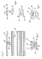
- FIG. 4 shows yet another illustration of the carrying and padding device made of glass carrier 22, glazing bridge 23 and spacer block 25.
- FIG. 5 shows a front view of the superimposed individual parts of the support and Blocking device according to Figures 3 and 4 in a side view.
- the spreading feet 29 have hook-shaped projections which provide a secure fit of the Ensure spacer blocks in the glass carrier 22.
- FIG. 6 shows the components of FIG. 5 in a side view.
- the spacer block 25 on both sides of the latching arms 30 which in a first assembly step behind a cutout 31 of the glazing bridge snap and thus connect both parts firmly together.
- the three Components then form the pre-assembled carrying and padding device.
- the carrying and padding device according to FIG. 7 has a bearing between the glass carrier 9 and the glazing bridge 14 a pivot bearing with a bearing pin 34 at the Glazing bridge 14, which in bearing recesses or eyes 35 on projections 36 of the corresponding component - here the glass carrier 9 - engages.
- Conceivable would also be a reverse arrangement of the bearing elements on the components glass carrier and glazing bridge. Even with this arrangement is a simple way Compensation of disc tolerances such as misalignment etc. possible.
Abstract
Description
Die Erfindung betrifft eine Trage- und Klotzungsvorrichtung nach dem Oberbegriff des
Anspruches 1.The invention relates to a carrying and padding device according to the preamble of
Eine derartige Trage- und Klotzungsvorrichtung ist aus der DE 76 28 717 U bekannt. In dieser Schrift wird eine Trage- und Klotzungsvorrichtung beschrieben, die ein Klötzchen aufweist, das eine plane Oberfläche hat, die zur Glasrandseite hin zeigt und auf der gegenüberliegenden Seite im Übergangsbereich zum Rahmen eines Fensters, einer Tür oder einer Fassade mit einer direkt am Rahmenprofil anliegenden konkaven Fläche versehen ist.Such a carrying and padding device is known from DE 76 28 717 U. In This document describes a carrying and padding device which is a block having a flat surface facing the edge of the glass and on the opposite side in the transition region to the frame of a window, a door or a facade provided with a directly adjacent to the frame profile concave surface is.
Derart wird eine Wippe ausgebildet, die gewährleisten soll, daß die Flächenelemente stets gleichmäßig auf den Klötzchen abgestützt werden. Auf diese Weise ist es möglich, Toleranzunterschiede im Randbereich auszugleichen und die Kräfteresultierende gleichmäßig an einer zwischen den beiden äußeren Rändern der Flächenelemente liegenden Stelle in den Rahmen einzuleiten.Such a rocker is designed to ensure that the surface elements always be supported evenly on the blocks. In this way it is possible Tolerance differences in the border area to compensate and the Krafterresultierende evenly at a lying between the two outer edges of the surface elements Place in the frame.
Problematisch ist an diesem System jedoch, daß sich die Kräfteresultierende unter dem Einfluss unterschiedlicher Lasten mal zum Rahmen hin und vom Rahmen weg bewegen kann. Hierdurch ist eine eindeutige Lastbestimmung nicht möglich. Der Lastangriffspunkt verschiebt sich vielmehr.The problem with this system, however, is that the herbalists under the Move the influence of different loads towards the frame and away from the frame can. As a result, a clear determination of the load is not possible. The load application point rather shifts.
Besonders nachteilig ist es ferner, daß die gesamte Last auf einer Linie bzw. einer sehr kleinen Fläche abgetragen wird. Hierdurch können keine großen Lasten, also große Flächenelemente aufgenommen werden, da sonst die Klötzchen und/oder das Profil zerstört werden. It is also particularly disadvantageous that the entire load on a line or a very small area is removed. As a result, no large loads, so large surface elements be absorbed, otherwise the blocks and / or destroyed the profile become.
Große Lasten von Flächenelementen verursachen ein Neigen der Tragprofile. Dadurch entsteht eine Torsionsbewegung von Profilen, wodurch die Auflagefläche nicht mehr winklig zur Elementfläche hin ausgerichtet ist. Auch hierdurch verschiebt sich der Lastangriffspunkt.Large loads of surface elements cause tilting of the supporting profiles. Thereby creates a torsional movement of profiles, whereby the support surface is no longer is aligned at an angle to the element surface. This also shifts the load application point.
Problematisch ist ferner, daß nach dem Stand der Technik die Klötzchen lose unter den Flächenelementen positioniert werden, so daß es leicht zu einem Verschieben und zu Montageproblemen kommen kann.A further problem is that according to the prior art, the blocks loosely under the Surface elements are positioned so that it is easy to move and to Assembly problems can come.
Ausgehend von diesem Stand der Technik ist es die Aufgabe der Erfindung, die Trageund Klotzungsvorrichtung für Flächenelemente derart weiter zu entwickeln, daß eine besonders hoher Belastbarkeit und ein Ausgleich von Toleranzen des Flächenelementes möglich ist. Bevorzugt sollen auch eine leichte und sichere Montage gewährleistet werden.Based on this prior art, it is the object of the invention, the wear and Blocking device for surface elements to develop such that a particularly high load capacity and a compensation of tolerances of the surface element is possible. Preferably, an easy and safe installation should be ensured.
Die Erfindung löst diese Aufgabe durch den Gegenstand des Anspruches 1.The invention solves this problem by the subject matter of
Vorteilhafte Ausgestaltungen sind den Unteransprüchen zu entnehmen.Advantageous embodiments can be found in the dependent claims.
Nach Anspruch 1 weist die Trage- und Klotzungsvorrichtung eine mehrteilige Ausbildung
mit einem Glasträger und einer Verglasungsbrücke auf, welche wippen- und/oder
lagerartig zusammenwirken, um die Ausrichtung von Isolierglasscheibe und Rahmenprofil
auszugleichen.According to
Derart wird eine Trage- und Klotzungsvorrichtung geschaffen, die auf einfache Weise montierbar und dabei unverlierbar am Rahmenprofil befestigt ist. Ferner wird ein Lager bereitgestellt, das dazu in der Lage ist, besonders hohe Lasten abzutragen, ohne dass die Nachteile des Standes der Technik auftreten, wonach die Krafteinleitung durch die auf einer ebenen Fläche abrollenden konkaven Ansatz stets an unterschiedlicher Stelle erfolgt.Thus, a carrying and padding device is provided which is simple can be mounted and thereby fixed captive on the frame profile. Furthermore, a warehouse provided that is able to remove particularly high loads without the Disadvantages of the prior art occur, after which the introduction of force through the on A concave approach rolling off a flat surface always takes place at a different location.
Bevorzugt ist der Glasträger im Glasfalz festgelegt, insbesondere in einer Schraubnut des Rahmenprofils, insbesondere eines Riegelprofils einer Fassade. The glass carrier is preferably fixed in the glazing rebate, in particular in a screw groove the frame profile, in particular a latch profile of a facade.
Nach einer bevorzugten Variante weist der Glasträger an seiner zum Flächenelement gewandten Seite eine Lagerausnehmung oder einen Lageransatz auf, der mit einem korrespondierend geformten Lageransatz oder einer korrespondierend geformten Lagerausnehmung an der Verglasungsbrücke zusammenwirkt und derart die wippen- und lagerartige Anordnung ausbildet. Durch den stets vorhandenen Eingriff des Ansatzes in die Ausnehmung und die damit erzwungene Lastabtragung stets in diesem definierten Bereich wird eine definierte Lastabtragung realisiert, welche es ermöglicht, die auftretenden Kräfte genau zu berechnen.According to a preferred variant, the glass carrier has on its surface element turned side on a bearing recess or a bearing neck on, with a corresponding shaped bearing lug or a correspondingly shaped bearing recess cooperates on the glazing bridge and so the rocker and camp-like arrangement forms. Through the ever-present engagement of the approach in the recess and thus enforced load transfer always defined in this In the area a defined load transfer is realized, which enables the accurately calculate occurring forces.
Nach einer Variante sind die Lagerausnehmung konkav und der Lageransatz konvex geformt (z.B. annähernd halbzylindrisch). Diese Variante ist leicht herstellbar und baut besonders kompakt.According to a variant, the bearing recess are concave and the bearing projection convex shaped (e.g., approximately semi-cylindrical). This variant is easy to manufacture and build very compact.
Es ist aber auch denkbar, dass die Lagerausnehmung als halbkugelartige oder ovale oder tonnenartige Lagerpfanne und der Lageransatz als korrespondierender kalottenartiger, insbesondere halbkugelartiger oder ovaler oder tonnenartiger Vorsprung ausgeformt ist, der in die korrespondierende kalottenartige, insbesondere halbkugelartige oder ovale oder tonnenartige Lagerausnehmung eingreift. Derart wird auf einfache Weise ein Toleranzausgleich in mehreren Richtungen sichergestellt, die Krafteinleitung stets am definierten Ort gewährleistet und eine definierte Festlegung der Scheibe auch senkrecht zur Ebene der Fig.1 realisiert.But it is also conceivable that the bearing recess as a hemispherical or oval or barrel-like cup and the bearing shoulder as a corresponding cup-like, In particular hemispherical or oval or barrel-like projection is formed, in the corresponding dome-shaped, in particular hemispherical or oval or barrel-like bearing recess engages. This way, a tolerance compensation becomes easy ensured in several directions, the force is always at the defined Guaranteed place and a defined fixing of the disc also perpendicular to Level of Fig.1 realized.
Nach einer weiteren Variante ist zwischen dem Glasträger und der Verglasungsbrücke ein Drehlager mit einem Lagerbolzen ausgebildet, der in wenigstens eine entsprechende Lagerausnehmung am korrespondiereden Bauelement eingreift. Gegenüber der Lösung mit Lageransatz und korrespondierender Ausnehmung wird hier der konstruktive Aufwand etwas erhöht, aber dennoch noch mit einfachen Mitteln ein Toleranzausgleich realisiert.According to another variant is between the glass carrier and the glazing bridge a pivot bearing with a bearing pin formed in at least one corresponding Bearing recess engages the corre sponding component. Opposite the solution with bearing neck and corresponding recess here is the design effort slightly increased, but still realized with simple means a tolerance compensation.
Es ist vorteilhaft, wenn der Glasträger als stabiler und leichter Metallprofilabschnitt ausgebildet ist, der eine Hohlkammer aufweist. It is advantageous if the glass carrier as a stable and lighter metal profile section is formed, which has a hollow chamber.
Vorzugsweise sind zur Abtragung besonders hoher Lasten mindestens ein Stützfuß oder mehrere Stützfüße an den Glasträger angeformt, die zur Abstützung des Glasträgers am Rahmenprofil ausgelegt sind, insbesondere derart, dass sich der wenigstens eine Stützfuß am Riegelprofil zwischen der Schraubnut und den Dichtungsnuten abstützt.Preferably, for the removal of particularly high loads at least one support leg or several support feet molded onto the glass carrier, which support the glass carrier on Frame profile are designed, in particular such that the at least one support leg supported on the bolt profile between the screw groove and the sealing grooves.
Nach einer weiteren besonders vorteilhaften Ausgestaltung bilden der Glasträger und die Verglasungsbrücke eine einfach handhabbare, vormontierte Einheit. Dabei ist es vorteilhaft, wenn der Glasträger und die Verglasungsbrücke mittels eines (Rast-)Dübels miteinander verbunden sind. So kann der Rastdübel als Rastdübelfuß ausgebildet sein, der an eines der Bauelemente der Trage- und Klotzungsvorrichtung angeformt ist. Zweckmäßig ist der Rastdübelfuß an die Verglasungsbrücke oder den Distanzklotz angeformt und durchsetzt die weiteren Bauelemente der Trage- und Klotzungsvorrichtung.According to a further particularly advantageous embodiment of the glass carrier and The glazing bridge is an easy-to-handle, preassembled unit. That's it advantageous if the glass carrier and the glazing bridge by means of a (detent) dowel connected to each other. Thus, the dowel can be designed as a dowel base, which is formed on one of the components of the carrying and padding device. The dowel foot is expediently integrally formed on the glazing bridge or spacer block and passes through the other components of the carrying and padding device.
So können der Glasträger und die Verglasungsbrücke über einen Rastdübelfuß miteinander verbunden sein, der entweder direkt an die Verglasungsbrücke mittels eines separaten Dübels oder an einen Distanzklotz angeformt ist und zum Eingriff in das korrespondierende Element Verglasungsbrücke oder Glasträger ausgelegt ist.Thus, the glass carrier and the glazing bridge to each other via a dowel base connected either directly to the glazing bridge by means of a separate Dowel or is formed on a spacer block and to engage in the corresponding Element glazing bridge or glass carrier is designed.
Durch die Vormontage wird sichergestellt, dass trotz der Möglichkeit zum Toleranzausgleich der Einbau der Scheibe gegenüber einem Einsatz einfacher Klotzungsstücke nicht erschwert wird. Der Toleranzausgleich erfolgt vielmehr quasi "automatisch" ohne dass der Monteur besondere Maßnahmen ergreifen muss.Pre-assembly ensures that, despite the possibility of tolerance compensation the installation of the disc against a use of simple block pieces not is difficult. The tolerance compensation is done almost "automatically" without that the installer must take special measures.
Bevorzugt sind der Glasträger und/oder die Verglasungsbrücke als Leichtmetallprofil ausgebildet und die Verglasungsbrücke besteht zumindest in ihrem dem Flächenelement zugewandten Bereich aus Kunststoff oder ist mit einem Distanzklotz aus Kunststoff versehen, um das Flächenelement zu schonen.Preferably, the glass carrier and / or the glazing bridge as a light metal profile formed and the glazing bridge exists at least in their the surface element facing area of plastic or is made with a plastic spacer provided to protect the surface element.
Nachfolgend wird die Erfindung unter Bezug auf die Zeichnungen anhand von Ausführungsbeispielen näher beschrieben. Es zeigt:
Figur 1- einen Schnitt durch eine Riegel-Pfosten-Konstruktion einer Fassade,
Figur 2- einen Schnitt durch die Riegel-Pfosten-Konstruktion aus
Figur 1 mit einer anderen Trage- und Klotzungsvorrichtung; - Figur 3
- einen Schnitt durch ein Riegelprofil einer weiteren Riegel-PfostenKonstruktion mit einer Trage- und Klotzungsvorrichtung;
- Figur 4
- eine schematisch vereinfachte Darstellung einer Trage- und Klotzungsvorrichtung,
Figur 5- Einzelelemente der Trage- und Klotzungsvorrichtung aus Fig. 4 nach einer ersten Ansicht;
Figur 6- die Elemente aus Figur 4 und 5 in einer zweiten Ansicht; und
Figur 7- eine schematisch vereinfachte Darstellung einer weiteren Trage- und Klotzungsvorrichtung.
- FIG. 1
- a section through a transom-post construction of a facade,
- FIG. 2
- a section through the latch-post construction of Figure 1 with another carrying and padding device;
- FIG. 3
- a section through a bolt profile of another bolt-post construction with a carrying and padding device;
- FIG. 4
- a schematically simplified representation of a carrying and padding device,
- FIG. 5
- Individual elements of the carrying and padding device of Figure 4 after a first view.
- FIG. 6
- the elements of Figures 4 and 5 in a second view; and
- FIG. 7
- a simplified schematic representation of another carrying and padding device.
Figur 1 zeigt einen Schnitt durch eine erste Riegel-Pfosten-Konstruktion einer Fassade
im Bereich des hier nur teilweise dargestellten Riegelprofils 1.FIG. 1 shows a section through a first transom-post construction of a facade
in the region of the
An den äußeren Rändern des Riegelprofils 1 sind nach außen gerichtete, hinterschnittene
Nuten 2 angeordnet, in die Anlagedichtungen 3 eingesetzt sind, die zur Anlage an
einer Isolierglasscheibe 8 dienen.At the outer edges of the
Auf der dem Riegelprofil 1 gegenüberliegenden Seite der Isolierglasscheibe 8 ist ein
Halteprofil 5 angeordnet, das nach innen gerichtete hinterschnittene Nuten 6 aufweist,
in die weitere Anlagedichtungen, nämlich die Glasdichtungen 7, eingesetzt sind.On the
Anstelle von Isolierglasscheiben 8 können auch andere Flächenelemente zwischen den Anlagedichtungen 3 und den Glasdichtungen 7 angeordnet werden.Instead of insulating glass panes 8, other surface elements between the Plant seals 3 and the glass seals 7 are arranged.
Das Riegelprofil 1 ist zu den Isolierglasscheiben 8 hin im Bereich seiner horizontalen
Symmetrieachse S mit einer Schraubnut 4 versehen, in der beispielsweise das Halteprofil
5 festlegbar ist. In die Schraubnut 4 können auch Isolatoren (hier nicht dargestellt)
und/oder weitere Funktionselemente eingesetzt werden.The
Nach Figur 1 dient die Schraubnut 4 auch zur Festlegung einer Trage- und Klotzungsvorrichtung für die Isolierglasscheiben 8.According to Figure 1, the Schraubnut 4 also serves to establish a carrying and padding device for the insulating glass panes 8.
Die mehrteilige Trage- und Klotzungsvorrichtung der Fig. 1 weist einen Glasträger 9
auf, der als Abschnitt eines Hohlprofils ausgebildet und entsprechend mit einer Hohlkammer
10 versehen ist. Es greift mit einem Rastansatz in die Schraubnut (4) ein oder
wird in dieser mit wenigstens einer Schraube festgeschraubt.The multi-part carrying and padding device of FIG. 1 has a
An die Hohlkammer 10 bzw. den rechteckigen Grundbereich des Glasträgers 9 sind
einstückig Stützfüße 11 und 12 angeformt, die sich jeweils gemäß Figur 1 oberhalb und
unterhalb der Schraubnut 4 erstrecken und sich sodann am Riegelprofil 1 jeweils oberhalb
und unterhalb der Schraubnut 4 zwischen dem Bereich der Schraubnut 4 und den
hinterschnittenen Nuten 2 abstützen, so daß der Glasträger 9 besonders hohe vertikale
Kräfte aufnehmen kann, die - wie in Figur 1 zu erkennen - beispielsweise die von oben
auf ihn wirkende Glasscheibe 8 auf ihn ausüben.To the
Der Glasträger 9 ist mit einer konkaven, rinnenartigen Aussparung 32 versehen, die einen
Teil eines Lagers 13 ausbildet. In die rinnenartigen Aussparung greift eine zur Geometrie
der Rinne korrespondierend mit einem konvexen Ansatz 33 versehene Verglasungsbrücke
14 ein.The
Der Glasträger 9 und die Verglasungsbrücke 14 nach Fig. 1 bilden eine wippenartige
Lageranordnung, welche den Vorteil hat, daß sich die theoretisch parallelen Flächen
vom Auflager der Isolierglasscheibe 8 und der Symmetrieachse des Riegelprofils 1 hier
ausgleichen. Bekanntermaßen wird die theoretische Parallelität dieser Elemente
beeinflußt durch unterschiedliche Aufstützflächen der einzelnen Glasscheiben der Isolierglasscheibe,
wenn diese z.B. unterschiedlich groß sind und/oder sich unterschiedliche
Gewichtslasten der Scheiben einer Isolierglasscheibe (z.B. außen 12 und innen 4
mm starke Scheiben) und/oder durch eine Schiefstellung der Symmetrieachse durch
Torsionskräfte bei großen Lasten der Flächenelemente und/oder durch Bewegungen der
Flächenelemente bei Windlasten. Denkbar wäre beispielsweise auch ein kalottenartiger
Ansatz in einer kalottenartigen Lagerpfanne. Der Schnitt der Fig. 1 bliebe dann im
Grunde unverändert. Sichergestellt würde aber auch ein Ausgleich von Toleranzen in
der Scheibe senkrecht zur Ebene der Fig. 1 und insbesondere auch eine Festlegung
senkrecht zur Scheibenebene. Bevorzugt wird jede Scheibe zumindest mit wenigstens
zwei derartigen Trage- und Klotzungsvorrichtungen am unteren Rand gehalten.The
Zwar ist es aus dem eingangs genannten Stand der Technik bereits bekannt, eine wippenartige Ausbildung der Klotzungsvorrichtung vorzunehmen. Diese hat jedoch den Nachteil, daß das konkave Klotzungsklötzchen auf einer ebenen Fläche aufliegt, so daß durch Ausgleichsbewegungen immer wieder unterschiedliche Lastpunkte beaufschlagt werden.Although it is already known from the aforementioned prior art, a rocker-like Make the formation of the blocking device. However, this has the Disadvantage that the concave Klotzungsklötzchen rests on a flat surface, so that By balancing movements repeatedly applied different load points become.
Diesen Nachteil vermeidet die Erfindung, denn durch die Anordnung der Wippe direkt
zwischen Glasträger 9 und Verglasungsbrücke 14 findet die Lastabtragung annähernd
immer am selben Ort bzw. jedenfalls im Bereich des Lagers statt.This disadvantage avoids the invention, because of the arrangement of the rocker directly
between
Zur Vereinfachung der Montage sind der Glasträger 9 und die Verglasungsbrücke 14
ergänzend durch einen Rastdübel 15, der Rastfüße aufweist, zu einer vormontierten
Einheit miteinander verbunden. Dies führt zu Montagevorteilen. Der Glasträger 9 und
die Verglasungsbrücke 14 werden derart also als vormontierte Einheit bereitgestellt.To simplify the assembly, the
Figur 2 zeigt eine Konstruktion analog zu Figur 1, wobei hier allerdings an den Glasträger
16 mit Hohlkammer 17 und Lager 18 sowie wippenartige ausgebildeter Verglasungsbrücke
19 ein oberer Fuß 11, nicht aber der "untere Fuß" 12 angeformt ist. Auch
diese Anordnung ist voll funktionsfähig. Der zweite Fuß hilft aber bei der Abtragung
besonders hoher Lasten.Figure 2 shows a construction analogous to Figure 1, in which case, however, to the
Im Lager 18 befindet sich wiederum die wippenartig ausgebildete Verglasungsbrücke
19, an die aber hier vorteilhaft einstückig ein Rastdübelfuß 20 angeformt ist, der in die
Verglasungsbrücke 19 eingreift. Die Krümmung des konkaven Bereichs ist hier stärker
als in Fig. 1, so dass größere Kippstellungen auf engem Raum realisierbar sind.In the
Alternativ könnte bei einer "umgekehrten" Anordnung der konvexe Ansatz auch an den
Glasträger 16 angeformt und die konkave Ausnehmung in der Verglasungsbrücke ausgebildet
werden (hier nicht dargestellt).Alternatively, in a "reverse" arrangement, the convex approach could also be applied to the
Auch Figur 3 zeigt einen Schnitt durch ein Riegelprofil einer Riegel-Pfosten-Konstruktion
mit einer bevorzugten Trage- und Klotzungsvorrichtung. Diese weitere Trage- und
Klotzungsvorrichtung - siehe auch Fig. 4 - besteht aus drei Teilen, nämlich aus dem
Glasträger 22, der wiederum eine Hohlkammer 10 sowie Füße 11 und 12 aufweist, aus
einer Verglasungsbrücke 23, die wiederum wippenartig in dem Lager 24 der Verglasungsbrücke
22 angeordnet ist und einen Distanzklotz 25, welcher die Verglasungsbrücke
23 klipsartig umgreift und einen einstückig angeformten Rastdübelansatz 26 aufweist.
Bevorzugt wird der Distanzklotz 25 aus Kunststoff gefertigt.Also Figure 3 shows a section through a bolt profile of a bolt-post construction
with a preferred wearing and padding device. These more carry and
Blocking device - see also Fig. 4 - consists of three parts, namely from the
Der klipsbare Rastdübelansatz 26 greift in ein Langloch (hier nicht dargestellt) des
Glasträgers 22 ein, so daß die drei Bauteile unverlierbar aber beweglich miteinander
schwenkbar, lagerartig verbunden sind. Derart ergibt sich eine besonders definierte
Lastabtragung im Lagerbereich und darüber hinaus erhebliche Montagevorteile durch
die zusammenhängende Ausführung des gesamten Trage- und Klotzungsvorrichtungssystems.The clipable locking
So ist es möglich, durch die erfindungsgemäße Lagerausgestaltung des Trage- und Klotzungsvorrichtungssystems erhebliche Lasten von bis zu 500 kg auf einfache Weise abzutragen.Thus, it is possible by the inventive bearing design of the carrying and Logging system can easily handle significant loads of up to 500kg ablate.
Die Figur 4 zeigt noch einmal eine weitere Darstellung der Trage- und Klotzungsvorrichtung
aus Glasträger 22, Verglasungsbrücke 23 und Distanzklotz 25.FIG. 4 shows yet another illustration of the carrying and padding device
made of
Figur 5 zeigt eine Vorderansicht der übereinander angeordneten Einzelteile der Trageund
Klotzungsvorrichtung nach Figur 3 und 4 in einer Seitenansicht. Gut zu erkennen
sind hierbei der Rastdübelansatz 26 des Distanzklotzes 25 sowie eine Kerbe 28 im
Rastdübelansatz 26, die dazu dient, die Spreizfüße 29 bei der Montage des Distanzklotzes
nach innen federnd auszulegen.Figure 5 shows a front view of the superimposed individual parts of the support and
Blocking device according to Figures 3 and 4 in a side view. Clearly visible
Here are the
Die Spreizfüße 29 weisen hakenförmige Vorsprünge auf, die einen sicheren Halt des
Distanzklotzes im Glasträger 22 gewährleisten.The spreading
Figur 6 zeigt die Bauteile der Figur 5 in einer Seitenansicht. Um die Vormontage dieser
Bauteile zu erleichtern weist der Distanzklotz 25 beidseitig die Rastarme 30 auf, die in
einem ersten Montageschritt hinter einen Freischnitt 31 der Verglasungsbrücke rasten
und somit beide Teile fest miteinander verbinden.FIG. 6 shows the components of FIG. 5 in a side view. To the pre-assembly of this
To facilitate components, the
Im zweiten Montageschritt wird dann die Verglasungsbrücke 23 mit dem Distanzklotz
25 auf den Glasträger 22 gesetzt und mit dem Rastdübelansatz 26 verrastet. Die drei
Bauteile bilden sodann die vormontierte Trage- und Klotzungsvorrichtung. In the second assembly step then the
Die Trage- und Klotzungsvorrichtung nach Fig. 7 weist als Lager zwischen dem Glas
träger 9 und der Verglasungsbrücke 14 ein Drehlager mit einem Lagerbolzen 34 an der
Verglasungsbrücke 14 auf, der in Lagerausnehmungen bzw. -augen 35 an Vorsprüngen
36 des korrespondierenden Bauelementes - hier der Glasträger 9 - eingreift. Denkbar
wäre auch eine umgekehrte Anordnung der Lagerelemente an den Bauelementen Glasträger
und Verglasungsbrücke. Auch mit dieser Anordnung ist auf einfache Weise ein
Ausgleich von Scheibentoleranzen wie Schiefstellungen usw. möglich. The carrying and padding device according to FIG. 7 has a bearing between the
- Riegelprofiltransom profile
- 11
- Nutgroove
- 22
- Anlagedichtungconditioning seal
- 33
- Schraubnutscrew groove
- 44
- Halteprofilretaining profile
- 55
- Nutgroove
- 66
- Glasdichtungglass seal
- 77
- Isolierglasscheibeinsulating glass pane
- 88th
- Glaskörpervitreous
- 99
- Hohlkammerhollow
- 1010
- StützfußSupport foot
- 1111
- StützfußSupport foot
- 1212
- Lagercamp
- 1313
- Verglasungsbrückeglazing bridge
- 1414
- Dübeldowel
- 1515
- Glasträgerglass slides
- 1616
- Hohlkammerhollow
- 1717
- Lagercamp
- 1818
- Verglasungsbrückeglazing bridge
- 1919
- Dübelfußdowel foot
- 2020
- Glasträgerglass slides
- 2222
- Verglasungsbrückeglazing bridge
- 2323
- Lagercamp
- 2424
- Distanzklotzdistance block
- 2525
- Dübelansatzdowel approach
- 2626
- Kerbescore
- 2828
- Spreizfußsplayfoot
- 2929
- Rastarmdetent arm
- 3030
- FreischnittClear cut
- 3131
- Lagerausnehmungbearing recess
- 3232
- Lageransatzbearing projection
- 3333
- Lagerbolzenbearing bolt
- 3434
- Lageraugenbearing eyes
- 3535
- Vorsprüngeprojections
- 3636
Claims (16)
Applications Claiming Priority (2)
| Application Number | Priority Date | Filing Date | Title |
|---|---|---|---|
| DE200420000550 DE202004000550U1 (en) | 2004-01-15 | 2004-01-15 | Carrying and padding device |
| DE202004000550U | 2004-01-15 |
Publications (2)
| Publication Number | Publication Date |
|---|---|
| EP1555377A2 true EP1555377A2 (en) | 2005-07-20 |
| EP1555377A3 EP1555377A3 (en) | 2006-11-02 |
Family
ID=32049852
Family Applications (1)
| Application Number | Title | Priority Date | Filing Date |
|---|---|---|---|
| EP04030766A Withdrawn EP1555377A3 (en) | 2004-01-15 | 2004-12-24 | Mounting and spacer device |
Country Status (2)
| Country | Link |
|---|---|
| EP (1) | EP1555377A3 (en) |
| DE (1) | DE202004000550U1 (en) |
Cited By (2)
| Publication number | Priority date | Publication date | Assignee | Title |
|---|---|---|---|---|
| US8826611B2 (en) | 2010-12-23 | 2014-09-09 | Saint-Gobain Performance Plastics Corporation | Structural glazing spacer |
| DE102016122687A1 (en) * | 2016-11-24 | 2018-05-24 | Hueck Gmbh & Co. Kg | Post and beam facade |
Families Citing this family (4)
| Publication number | Priority date | Publication date | Assignee | Title |
|---|---|---|---|---|
| DE202007004060U1 (en) | 2007-03-15 | 2007-05-24 | Sälzer Sicherheitstechnik GmbH | Closing-off device for gap in building has inner frame profile positively coupled to connecting profile which is itself connected to outer frame profile |
| DE102012111432A1 (en) * | 2012-11-26 | 2014-05-28 | SCHÜCO International KG | Window, door or façade element with a sealing profile with integrated light source |
| DE102012111442A1 (en) * | 2012-11-26 | 2014-05-28 | SCHÜCO International KG | Window, door or façade element with a glass bridge with integrated light source |
| DE102016109913A1 (en) * | 2016-05-30 | 2017-11-30 | seele group GmbH & Co. KG | Arrangement with at least two surface elements connected to one another via a spacer and a bearing associated with the surface elements |
Citations (1)
| Publication number | Priority date | Publication date | Assignee | Title |
|---|---|---|---|---|
| DE7628717U1 (en) | 1976-09-14 | 1978-01-05 | Straub, Theodor, 8857 Gottmannshofen | DISC PUMPING |
Family Cites Families (10)
| Publication number | Priority date | Publication date | Assignee | Title |
|---|---|---|---|---|
| US2300485A (en) * | 1940-02-12 | 1942-11-03 | Pittsburgh Plate Glass Co | Panel setting device |
| US2595927A (en) * | 1947-02-03 | 1952-05-06 | Kawneer Co | Glass setting device |
| US2612663A (en) * | 1947-02-06 | 1952-10-07 | Libbey Owens Ford Glass Co | Glass setting device |
| US4428171A (en) * | 1982-03-12 | 1984-01-31 | Atlantic Richfield Company | Thermal storefront system |
| DE3643607A1 (en) * | 1985-12-20 | 1987-07-02 | Hahn Glasbau | Carrying apparatus for glass panes |
| NL8701564A (en) * | 1987-07-03 | 1989-02-01 | Blitta B V | Glass panel facade for building - includes profiled support sections filed with silicone mastic |
| DE3742723C1 (en) * | 1987-12-17 | 1988-09-15 | Wieland Werke Ag | Frame structure by the post/crossmember construction method, in particular for facades, roofs or the like |
| EP0587967A1 (en) * | 1992-09-18 | 1994-03-23 | PANDOLFO ALLUMINIO S.r.l. | A sectional structure for erecting roof and wall frames |
| DE29601640U1 (en) * | 1996-01-31 | 1996-03-21 | Kaese Gerhard | Device for the temporary holding of insert parts in transom and mullion facades. |
| DE10160003A1 (en) * | 2001-12-06 | 2003-06-26 | Hans Dieter Niemann | Support part of a glazing |
-
2004
- 2004-01-15 DE DE200420000550 patent/DE202004000550U1/en not_active Expired - Lifetime
- 2004-12-24 EP EP04030766A patent/EP1555377A3/en not_active Withdrawn
Patent Citations (1)
| Publication number | Priority date | Publication date | Assignee | Title |
|---|---|---|---|---|
| DE7628717U1 (en) | 1976-09-14 | 1978-01-05 | Straub, Theodor, 8857 Gottmannshofen | DISC PUMPING |
Cited By (4)
| Publication number | Priority date | Publication date | Assignee | Title |
|---|---|---|---|---|
| US8826611B2 (en) | 2010-12-23 | 2014-09-09 | Saint-Gobain Performance Plastics Corporation | Structural glazing spacer |
| US9272499B2 (en) | 2010-12-23 | 2016-03-01 | Saint-Gobain Performance Plastics Corporation | Structural glazing spacer |
| DE102016122687A1 (en) * | 2016-11-24 | 2018-05-24 | Hueck Gmbh & Co. Kg | Post and beam facade |
| EP3327215A1 (en) * | 2016-11-24 | 2018-05-30 | HUECK GmbH & Co. KG | Curtain wall façade with mullions and transoms |
Also Published As
| Publication number | Publication date |
|---|---|
| DE202004000550U1 (en) | 2004-03-18 |
| EP1555377A3 (en) | 2006-11-02 |
Similar Documents
| Publication | Publication Date | Title |
|---|---|---|
| DE3714629C2 (en) | Facade wall of a building | |
| EP1020575B1 (en) | T-connection between a mullion profile and a transom profile of a fassade or a glazed roof | |
| EP1580344B1 (en) | Butt joint for angular connection of hollow profiles, particularly for windows, doors and the like | |
| DE102010010249B4 (en) | Solar array | |
| EP1555377A2 (en) | Mounting and spacer device | |
| EP1302602B1 (en) | Mullion and transom construction consisting of assembled frame elements | |
| EP2194335A1 (en) | Fixing system for a solar collector | |
| EP1557516B1 (en) | Trolley for a sliding or folding door | |
| EP2088337A2 (en) | Profile and profile system | |
| EP0645504B1 (en) | Mullion-transom system | |
| EP2792830B1 (en) | Fitting element mit retaining element for holding said fitting element | |
| EP1346114B1 (en) | FAçADE AND/OR ROOF | |
| DE2334802A1 (en) | Clamping profile for fixing double glazing panels in window frame - has a spring locking profile for frame member exerting clamping force | |
| WO2003052227A1 (en) | Connector element for a glazed support bar construction | |
| DE3621942A1 (en) | FRAMELESS GLAZING | |
| EP0733254B1 (en) | Folding frame for a poster | |
| EP3351716A1 (en) | Door or window frame with a mounting frame | |
| DE10154058A1 (en) | Wood/aluminum window comprises elastic plastic profile pieces fixed on free arms of aluminum profiles and having protrusions gripping under undercut shoulders on wooden profiles | |
| EP3045649A1 (en) | Glazing rebate insert element for a window or a door | |
| EP0524631A1 (en) | Mounting device for insulating glazing | |
| EP3150792B1 (en) | Thermally isolated profile frame system | |
| EP0403609B1 (en) | Surrounding frame of elastic material for a flat element | |
| CH671999A5 (en) | Building window frame bar - is of aluminium T=section with elastic seal round crossbar accommodating trim strip | |
| EP3473796A1 (en) | Fixed glazing system for fixing a glass retaining strip with definable contact pressure | |
| EP3299569B1 (en) | Skylight |
Legal Events
| Date | Code | Title | Description |
|---|---|---|---|
| PUAI | Public reference made under article 153(3) epc to a published international application that has entered the european phase |
Free format text: ORIGINAL CODE: 0009012 |
|
| AK | Designated contracting states |
Kind code of ref document: A2 Designated state(s): AT BE BG CH CY CZ DE DK EE ES FI FR GB GR HU IE IS IT LI LT LU MC NL PL PT RO SE SI SK TR |
|
| AX | Request for extension of the european patent |
Extension state: AL BA HR LV MK YU |
|
| PUAL | Search report despatched |
Free format text: ORIGINAL CODE: 0009013 |
|
| AK | Designated contracting states |
Kind code of ref document: A3 Designated state(s): AT BE BG CH CY CZ DE DK EE ES FI FR GB GR HU IE IS IT LI LT LU MC NL PL PT RO SE SI SK TR |
|
| AX | Request for extension of the european patent |
Extension state: AL BA HR LV MK YU |
|
| STAA | Information on the status of an ep patent application or granted ep patent |
Free format text: STATUS: THE APPLICATION HAS BEEN WITHDRAWN |
|
| 17P | Request for examination filed |
Effective date: 20070104 |
|
| 18W | Application withdrawn |
Effective date: 20070206 |