EP1555344A1 - Beheizbare Walze - Google Patents
Beheizbare Walze Download PDFInfo
- Publication number
- EP1555344A1 EP1555344A1 EP04105657A EP04105657A EP1555344A1 EP 1555344 A1 EP1555344 A1 EP 1555344A1 EP 04105657 A EP04105657 A EP 04105657A EP 04105657 A EP04105657 A EP 04105657A EP 1555344 A1 EP1555344 A1 EP 1555344A1
- Authority
- EP
- European Patent Office
- Prior art keywords
- roller according
- jacket
- heat
- roller
- heatable
- Prior art date
- Legal status (The legal status is an assumption and is not a legal conclusion. Google has not performed a legal analysis and makes no representation as to the accuracy of the status listed.)
- Granted
Links
Images



Classifications
-
- F—MECHANICAL ENGINEERING; LIGHTING; HEATING; WEAPONS; BLASTING
- F16—ENGINEERING ELEMENTS AND UNITS; GENERAL MEASURES FOR PRODUCING AND MAINTAINING EFFECTIVE FUNCTIONING OF MACHINES OR INSTALLATIONS; THERMAL INSULATION IN GENERAL
- F16C—SHAFTS; FLEXIBLE SHAFTS; ELEMENTS OR CRANKSHAFT MECHANISMS; ROTARY BODIES OTHER THAN GEARING ELEMENTS; BEARINGS
- F16C13/00—Rolls, drums, discs, or the like; Bearings or mountings therefor
- F16C13/02—Bearings
- F16C13/022—Bearings supporting a hollow roll mantle rotating with respect to a yoke or axle
- F16C13/024—Bearings supporting a hollow roll mantle rotating with respect to a yoke or axle adjustable for positioning, e.g. radial movable bearings for controlling the deflection along the length of the roll mantle
- F16C13/026—Bearings supporting a hollow roll mantle rotating with respect to a yoke or axle adjustable for positioning, e.g. radial movable bearings for controlling the deflection along the length of the roll mantle by fluid pressure
- F16C13/028—Bearings supporting a hollow roll mantle rotating with respect to a yoke or axle adjustable for positioning, e.g. radial movable bearings for controlling the deflection along the length of the roll mantle by fluid pressure with a plurality of supports along the length of the roll mantle, e.g. hydraulic jacks
-
- D—TEXTILES; PAPER
- D21—PAPER-MAKING; PRODUCTION OF CELLULOSE
- D21G—CALENDERS; ACCESSORIES FOR PAPER-MAKING MACHINES
- D21G1/00—Calenders; Smoothing apparatus
- D21G1/02—Rolls; Their bearings
- D21G1/0206—Controlled deflection rolls
- D21G1/0213—Controlled deflection rolls with deflection compensation means acting between the roller shell and its supporting member
- D21G1/022—Controlled deflection rolls with deflection compensation means acting between the roller shell and its supporting member the means using fluid pressure
-
- D—TEXTILES; PAPER
- D21—PAPER-MAKING; PRODUCTION OF CELLULOSE
- D21G—CALENDERS; ACCESSORIES FOR PAPER-MAKING MACHINES
- D21G1/00—Calenders; Smoothing apparatus
- D21G1/02—Rolls; Their bearings
- D21G1/0253—Heating or cooling the rolls; Regulating the temperature
- D21G1/0266—Heating or cooling the rolls; Regulating the temperature using a heat-transfer fluid
- D21G1/0273—Heating or cooling the rolls; Regulating the temperature using a heat-transfer fluid on the exterior surface of the rolls
Definitions
- the invention relates to a heatable roller, in particular for thermal Treatment of Materialbahbnen, with a circulating around a support system Roll shell.
- the invention is based on the object, an improved heatable roller of the aforementioned type, in which the outer shell is heated separately from the support system or the roll core.
- the roll shell a heatable outer sheath and a between this outer sheath and comprises the heat-insulating inner jacket arranged in the support system.
- the outer sheath can now be separated from Support system are heated, preferably only the outer jacket heated is, that is, the support system or the roll core remains unheated.
- the roller is used as a deflection adjustment device. or deflection compensating roller, whose Supporting system a the roll shell axially passing through rotatable yoke and a plurality of successive in the axial direction, preferably includes hydraulic support elements.
- the heat-insulating Inner jacket preferably acted upon directly by the support elements.
- the heat-insulating inner jacket consists of a temperature-resistant Plastic.
- this heat-insulating inner jacket for example, Peek or the like exist.
- this sheath with a suitable tribological functional layer - e.g. a Teflon coating - to be provided to prevent downforce, otherwise due to the conceptually occurring relative movements arise could.
- a suitable tribological functional layer e.g. a Teflon coating -
- the roll can be designed in particular as a self-adjusting F-roll.
- an embodiment, for example, as concentric guided K-roller conceivable.
- Support elements is preferably a game between the heated outer jacket and the heat-insulating inner jacket. In operation, this is Advantageously by a corresponding thermal expansion of the game Inner jacket and / or lifted by the internal pressure.
- the heat-insulating inner sheath can be grooved on its outer circumference or be provided with at least one notch. Alternatively or additionally the heatable outer sheath grooved on its inner circumference or with at least be provided with a notch. To cool down the roller is in the grooved or notched area between outer shell and inner shell advantageously cold air can be injected.
- the heatable outer jacket is preferably made of steel.
- Roller is the heatable outer jacket on the heat-insulating inner jacket pushed.
- the outer jacket is heated from the outside.
- the outer jacket in particular from the outside, inductively heated.
- the induction loop is preferred with the F-gate movable, so that maintained a constant distance to the outer jacket can be.
- the heat-insulating inner jacket preferably has a smaller thickness as the heated outer jacket.
- the thickness of the heat-insulating inner shell for example, in a range of about 2 to about 15 mm and especially in one area from about 8 to about 15 mm.
- the heat-insulating has Inner sheath an average thickness of about 10 mm.
- the heated outer jacket can be provided with a rubber coating.
- rubber and suitable plastics are conceivable.
- a cantilever for hanging the roller in the Be provided for.
- the heatable outer jacket and the heat-insulating inner jacket can for example, also be glued together. According to heat-resistant Glues are already on the market.
- the roll according to the invention is of particular advantage in the production of nonwovens or similar materials, and in particular for solidification of the materials concerned. She is beyond that Advantage especially for certain textile finishing processes such in particular for the embossing of textiles, etc. applicable.
- roller according to the invention is advantageously also, for example, as respective counter roll can be used in a NipcoFlex calender.
- the roller according to the invention allows the use of simple, proven technology for bending compensation and heating separate from the support system of the roll mantle.
- the support system can therefore run cold or relatively cold become. It can be more or less every so-called NIPCO roller to one heated roller can be extended. Especially with wide webs, which are driven at high web speeds, this is significant Advantage.
- the heating energy can be applied directly from the outside and significantly higher power densities can be achieved.
- FIG. 1 and 2 show in a schematic longitudinal sectional view or in schematic cross-sectional view of an exemplary embodiment a heatable roller 10 according to the invention, in particular for thermal Treatment of webs is used.
- the revolving around a support system 12 roll shell 14 of this heated Roller 10 comprises a heatable outer jacket 14 'and an intermediate this and the support system 12 arranged heat-insulating inner jacket 14 ".
- the outer jacket 14 ' is thus heated separately from the support system 12, wherein preferably only the outer jacket 14 'is heated, that is, the support system 12 remains unheated or cold or relatively cold is operated.
- the roller 10 is designed as a deflection adjustment roller, the support system 12 a the roll shell 14 axially penetrating non-rotatable yoke 16 and a plurality of axially in the X direction following, preferably hydraulic support elements 18 includes.
- the support system 12 a the roll shell 14 axially penetrating non-rotatable yoke 16 and a plurality of axially in the X direction following, preferably hydraulic support elements 18 includes.
- two support element rows are provided (see FIG. 2).
- the heat-insulating inner jacket 14 is preferably made of a temperature-resistant Plastic, for example, peek or the like can exist.
- the roller 10 is a concentrically guided K-roller executed.
- the heat-insulating inner jacket 14 in particular be designed so that it simultaneously as a seal serves against the guide bearing.
- the outer periphery of the heat-insulating inner jacket 14 "and / or the Inner circumference of the heatable outer jacket 14 ' may be grooved or at least be provided with a notch. To cool down the roller 10 can then through the grooved or notched area between outer shell 14 ' and inner jacket 14 "cold air to be blown.
- the preferably made of steel heatable outer jacket 14 ' is simple on the heat-insulating inner jacket 14 "pushed.
- the outer jacket 14 ' is preferably heated from the outside. advantageously, This outer jacket 14 'is inductively heated. In the case of an F-roll, the Induction loop with the F-scenery be movable, allowing for a constant Distance to be heated outer shell 14 'is taken care of.
- the heat-insulating has Inner sheath 14 "a significantly smaller thickness than the heated outer sheath 14 '.
- the thickness of the heat-insulating inner jacket 14 " for example in a range of about 2 to about 15 mm and especially in a range of about 8 to about 15 mm.
- the heat-insulating has Inner sheath 14 "an average thickness of about 10 mm.
- the heatable outer jacket 14 ' may be provided with a rubber coating. In addition to rubber and suitable plastics are conceivable.
- a cantilever Suspension of the roller 10 may be provided in the flow. Such a cantilever is not mandatory.
- the roller 10 is of particular advantage in the production of nonwovens or similar materials and in particular for solidification of the applicable materials. It is also beneficial especially for certain textile finishing processes such as in particular for embossing textiles, etc. applicable. In particular, it is advantageous also use of the roll 10 as the respective counter roll of a NipcoFlex calender.
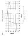
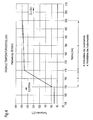
- FIGS. 3 to 7 show different diagrams for the radial temperature distribution over the double jacket of the roll for different surface temperatures, different wall thicknesses of the heat-insulating inner shell and different heating capacities. It was a heat-insulating Inner jacket made of peek provided. As with reference to these Figs. 3 to 7 recognize, losses inside are kept to a minimum.
Landscapes
- Physics & Mathematics (AREA)
- Fluid Mechanics (AREA)
- Engineering & Computer Science (AREA)
- General Engineering & Computer Science (AREA)
- Mechanical Engineering (AREA)
- Treatment Of Fiber Materials (AREA)
- Paper (AREA)
- Yarns And Mechanical Finishing Of Yarns Or Ropes (AREA)
- Rolls And Other Rotary Bodies (AREA)
Abstract
Description
- Fig. 1
- eine schematische Längsschnittdarstellung einer beispielhaften Ausführungsform der erfindungsgemäßen beheizbaren Walze,
- Fig. 2
- eine schematische Querschnittsdarstellung der Walze gemäß Fig. 1, geschnitten entlang der Linie A-A in Fig. 1, und
- Fig. 3 bis 7
- verschiedene Diagramme zur radialen Temperaturverteilung über dem Doppelmantel der Walze für unterschiedliche Oberflächentemperaturen, unterschiedliche Wandstärken des wärmeisolierenden Innenmantels und unterschiedliche Heizleistungen.
- 10
- beheizbare Walze
- 12
- Stützsystem
- 14
- Walzenmantel
- 14'
- beheizbarer Außenmantel
- 14"
- wärmeisolierender Innenmantel
- 16
- drehfestes Joch
- 18
- hydraulisches Stützelement
- d
- Wandstärke des Innenmantels
- e
- Wandstärke des Außenmantels
- X
- Axialrichtung
Claims (31)
- Beheizbare Walze (10), insbesondere zur thermischen Behandlung von Materialbahnen, mit einem um ein Stützsystem (12) umlaufenden Walzenmantel (14),
dadurch gekennzeichnet, dass der Walzenmantel (14) einen beheizbaren Außenmantel (14') und einen zwischen diesem Außenmantel (14') und dem Stützsystem (12) angeordneten wärmeisolierenden Innenmantel (14") umfasst. - Walze nach Anspruch 1,
dadurch gekennzeichnet, dass der Außenmantel (14') getrennt vom Stützsystem (12) beheizbar ist, wobei vorzugsweise nur der Außenmantel (14') beheizbar ist, d.h. das Stützsystem (12) unbeheizt bleibt. - Walze nach Anspruch 1 oder 2,
dadurch gekennzeichnet, dass sie als Durchbiegungseinstellwalze ausgeführt ist, deren Stützsystem (12) ein den Walzenmantel (14) axial durchsetzendes drehfestes Joch (16) sowie eine Mehrzahl von in Axialrichtung (X) aufeinander folgenden, vorzugsweise hydraulischen Stützelementen (18) umfasst. - Walze nach Anspruch 3,
dadurch gekennzeichnet, dass der wärmeisolierende Innenmantel (14") durch die Stützelemente (18) direkt beaufschlagbar ist. - Walze nach einem der vorhergehenden Ansprüche,
dadurch gekennzeichnet, dass der wärmeisolierende Innenmantel (14") aus einem temperaturbeständigen Kunststoff besteht. - Walze nach Anspruch 5,
dadurch gekennzeichnet, dass der wärmeisolierende Innenmantel (14") aus Peek oder dergleichen besteht. - Walze nach einem der vorhergehenden Ansprüche,
dadurch gekennzeichnet, dass der Außenmantel (14') und/oder der Innenmantel (14") mit einer tribologischen Funktionsschicht, z.B. einer Teflonschicht versehen ist. - Walze nach einem der vorhergehenden Ansprüche,
dadurch gekennzeichnet, dass sie als selbstanstellende F-Walze ausgeführt ist. - Walze nach einem der Ansprüche 1 bis 7,
dadurch gekennzeichnet, dass sie als konzentrisch geführte K-Walze ausgeführt ist. - Walze nach einem der vorhergehenden Ansprüche,
dadurch gekennzeichnet, dass der wärmeisolierende Innenmantel (14") gleichzeitig als Abdichtung gegenüber der Führungslagerung dient. - Walze nach einem der vorhergehenden Ansprüche,
dadurch gekennzeichnet, dass im nicht beheizten Zustand der Walze (10) und gegebenenfalls bei nicht aktivierten Stützelementen (18) ein Spiel zwischen dem beheizbaren Außenmantel (14') und dem wärmeisolierenden Innenmantel (14") vorliegt. - Walze nach Anspruch 11,
dadurch gekennzeichnet, dass das Spiel im Betrieb durch eine entsprechende Wärmeausdehnung des Innenmantels (14") und/oder durch den Innendruck aufgehoben wird. - Walze nach einem der vorhergehenden Ansprüche,
dadurch gekennzeichnet, dass der wärmeisolierende Innenmantel (14") an seinem Außenumfang gerillt oder mit wenigstens einer Kerbung ist. - Walze nach einem der vorhergehenden Ansprüche,
dadurch gekennzeichnet, dass der beheizbare Außenmantel (14') an seinem Innenfang gerillt bzw. mit wenigstens einer Kerbung versehen ist. - Walze nach Anspruch 13 oder 14,
dadurch gekennzeichnet, dass zum Herunterkühlen der Walze in den gerillten bzw. gekerbten Bereich zwischen Außenmantel (14') und Innenmantel (14") Kaltluft einblasbar ist. - Walze nach einem der vorhergehenden Ansprüche,
dadurch gekennzeichnet, dass der beheizbare Außenmantel (14') aus Stahl besteht. - Walze nach einem der vorhergehenden Ansprüche,
dadurch gekennzeichnet, dass der beheizbare Außenmantel auf den wärmeisolierenden Innenmantel (14") aufschiebbar ist. - Walze nach einem der vorhergehenden Ansprüche,
dadurch gekennzeichnet, dass der Außenmantel (14') von außen beheizbar ist. - Walze nach einem der vorhergehenden Ansprüche,
dadurch gekennzeichnet, dass der Außenmantel (14') induktiv beheizbar ist. - Walze nach Anspruch 19,
dadurch gekennzeichnet, dass im Fall einer F-Walze die Induktionsschleife mit der F-Kulisse bewegbar ist. - Walze nach einem der vorhergehenden Ansprüche,
dadurch gekennzeichnet, dass der wärmeisolierende Innenmantel (14") eine geringere Dicke als der beheizbare Außenmantel (14') besitzt. - Walze nach einem der vorhergehenden Ansprüche,
dadurch gekennzeichnet, dass die Dicke des wärmeisolierenden Innenmantels (14") in einem Bereich von etwa 2 bis etwa 15 mm und insbesondere in einem Bereich von etwa 8 bis etwa 15 mm liegt. - Walze nach einem der vorhergehenden Ansprüche,
dadurch gekennzeichnet, dass der wärmeisolierende Innenmantel (14") eine mittlere Dicke von etwa 10 mm besitzt. - Walze nach einem der vorhergehenden Ansprüche,
dadurch gekennzeichnet, dass der beheizbare Außenmantel (14') mit einer Gummierung oder einem Kunststoffbelag versehen ist. - Walze nach einem der vorhergehenden Ansprüche,
dadurch gekennzeichnet, dass ein Kantilever zum Aufhängen der Walze (10) in der Stuhlung vorgesehen ist. - Walze nach einem der vorhergehenden Ansprüche,
dadurch gekennzeichnet, dass auf der Bedienseite ein Lager zum Freilegen des abzuziehenden Außenmantels (14') vorgesehen ist. - Walze nach einem der vorhergehenden Ansprüche,
dadurch gekennzeichnet, dass der beheizbare Außenmantel (14') und der wärmeisolierende Innenmantel (14") miteinander verklebt sind. - Verwendung der Walze nach einem der vorhergehenden Ansprüche bei der Herstellung von Vliesstoffen oder ähnlichen Materialien.
- Verwendung der Walze nach einem der vorhergehenden Ansprüche zur Verfestigung von Vliesstoffen oder ähnlichen Materialien.
- Verwendung der Walze nach einem der vorhergehenden Ansprüche für textile Veredelungsprozesse wie insbesondere für das Prägen von Textilien.
- Verwendung der Walze nach einem der vorhergehenden Ansprüche als Gegenwalze eines NipcoFlex-Kalanders.
Applications Claiming Priority (2)
| Application Number | Priority Date | Filing Date | Title |
|---|---|---|---|
| DE102004002003A DE102004002003A1 (de) | 2004-01-14 | 2004-01-14 | Beheizbare Walze |
| DE102004002003 | 2004-01-14 |
Publications (2)
| Publication Number | Publication Date |
|---|---|
| EP1555344A1 true EP1555344A1 (de) | 2005-07-20 |
| EP1555344B1 EP1555344B1 (de) | 2009-01-07 |
Family
ID=34609544
Family Applications (1)
| Application Number | Title | Priority Date | Filing Date |
|---|---|---|---|
| EP04105657A Expired - Lifetime EP1555344B1 (de) | 2004-01-14 | 2004-11-10 | Beheizbare Walze |
Country Status (3)
| Country | Link |
|---|---|
| US (1) | US20050153819A1 (de) |
| EP (1) | EP1555344B1 (de) |
| DE (2) | DE102004002003A1 (de) |
Citations (2)
| Publication number | Priority date | Publication date | Assignee | Title |
|---|---|---|---|---|
| DE4126232A1 (de) * | 1991-05-03 | 1992-11-12 | Escher Wyss Gmbh | Durchbiegungseinstellwalze |
| DE9301417U1 (de) * | 1992-04-10 | 1993-04-01 | Sulzer-Escher Wyss GmbH, 7980 Ravensburg | Walze |
Family Cites Families (8)
| Publication number | Priority date | Publication date | Assignee | Title |
|---|---|---|---|---|
| US3447600A (en) * | 1966-09-23 | 1969-06-03 | Sw Ind Inc | Construction of roll for machinery and the manufacture thereof |
| US3810808A (en) * | 1968-04-12 | 1974-05-14 | Pervel Ind Inc | Apparatus for making plastic sheet material |
| DE3007943C2 (de) * | 1980-02-27 | 1983-09-08 | Escher Wyss AG, Zürich | Durchbiegungseinstellwalze |
| GB2207979B (en) * | 1987-08-08 | 1991-03-13 | Beloit Walmsley Ltd | Improvements in or relating to press rolls |
| FI83895C (fi) * | 1988-04-13 | 1991-09-10 | Valmet Paper Machinery Inc | Foerfarande och anordning vid pressbehandling av en pappersbana. |
| CH681863A5 (de) * | 1990-06-25 | 1993-06-15 | Escher Wyss Ag | |
| CA2086007C (en) * | 1991-05-03 | 1999-04-13 | Rolf Lehmann | Roll with adjustable deflection and its use |
| US5632861A (en) * | 1995-06-08 | 1997-05-27 | Beloit Technologies, Inc. | Alloy coating for wet and high temperature pressing roll |
-
2004
- 2004-01-14 DE DE102004002003A patent/DE102004002003A1/de not_active Withdrawn
- 2004-11-10 DE DE502004008815T patent/DE502004008815D1/de not_active Expired - Lifetime
- 2004-11-10 EP EP04105657A patent/EP1555344B1/de not_active Expired - Lifetime
- 2004-12-28 US US11/022,881 patent/US20050153819A1/en not_active Abandoned
Patent Citations (2)
| Publication number | Priority date | Publication date | Assignee | Title |
|---|---|---|---|---|
| DE4126232A1 (de) * | 1991-05-03 | 1992-11-12 | Escher Wyss Gmbh | Durchbiegungseinstellwalze |
| DE9301417U1 (de) * | 1992-04-10 | 1993-04-01 | Sulzer-Escher Wyss GmbH, 7980 Ravensburg | Walze |
Also Published As
| Publication number | Publication date |
|---|---|
| DE102004002003A1 (de) | 2005-08-04 |
| US20050153819A1 (en) | 2005-07-14 |
| DE502004008815D1 (de) | 2009-02-26 |
| EP1555344B1 (de) | 2009-01-07 |
Similar Documents
| Publication | Publication Date | Title |
|---|---|---|
| DE29902451U1 (de) | Vorrichtung zum Kalandrieren von Papier | |
| EP0221291A2 (de) | Walzenaggregat für Kalander, Glättwerke oder dergleichen sowie Verfahren zu seiner Herstellung | |
| EP0529385A1 (de) | Verfahren und Vorrichtung zur Glätte- und Glanzerzeugung | |
| DE19941336A1 (de) | Trocknungsvorrichtung | |
| AT506770B1 (de) | Walze | |
| DE3429695A1 (de) | Verfahren zur erzielung eines temperaturprofils im bereich hoher temperaturen an beheizten walzen und entsprechende walzeinrichtung | |
| EP2913435B1 (de) | Kalander | |
| EP1162045B1 (de) | Walzenvorrichtung | |
| EP1314819B1 (de) | Kalander und Verfahren zum Glätten einer Papier- oder Kartonbahn | |
| EP1555344B1 (de) | Beheizbare Walze | |
| DE112010003542T5 (de) | Walze mit einstellbarem Mantel, Vorrichtung und Verfahren | |
| EP1634994B1 (de) | Kalanderanordnung | |
| EP1285990B1 (de) | Vorrichtung zum Bilden eines Langspalts | |
| DE10207371B4 (de) | Vorrichtung zum Bilden eines Langspalts | |
| EP2194187A1 (de) | Kalander | |
| DE4317873A1 (de) | Hohler Walzenkörper zur Verwendung in einer Papiermaschine oder dergleichen Anlage zur Herstellung endlosen Bahnmaterials | |
| DE10157691B4 (de) | Kalander und Verfahren zum Glätten einer Faserstoffbahn | |
| DE10225256B4 (de) | Kalanderanordnung und Verfahren zum Behandeln einer Materialbahn | |
| EP1593778B1 (de) | Verfahren und Vorrichtung zum Behandeln einer Bahn aus Papier oder Karton | |
| DE102012209460A1 (de) | Bahnbehandlungsvorrichtung | |
| DE102007055734A1 (de) | Bahnbehandlungsvorrichtung | |
| AT502585B1 (de) | Durchbiegungseinstellwalze für papier-/kartonmaschinen oder ausrüstungsmaschinen | |
| EP1342840A1 (de) | Kalander und Verfahren zum Glätten einer Faserstoffbahn | |
| DE4310404A1 (en) | Hollow roller - has internal heating for mantle width covered by web material without heating uncovered edge zones | |
| AT513424B1 (de) | Anlage zur Wärmeübertragung in einer Faserbahnmaschine, Oberflächenbearbeitungsvorrichtung zur Bearbeitung der Faserbahnoberfläche und Trockenpartie einer Faserbahnmaschine |
Legal Events
| Date | Code | Title | Description |
|---|---|---|---|
| PUAI | Public reference made under article 153(3) epc to a published international application that has entered the european phase |
Free format text: ORIGINAL CODE: 0009012 |
|
| AK | Designated contracting states |
Kind code of ref document: A1 Designated state(s): AT BE BG CH CY CZ DE DK EE ES FI FR GB GR HU IE IS IT LI LU MC NL PL PT RO SE SI SK TR |
|
| AX | Request for extension of the european patent |
Extension state: AL HR LT LV MK YU |
|
| 17P | Request for examination filed |
Effective date: 20060120 |
|
| AKX | Designation fees paid |
Designated state(s): DE FI FR GB IT SE |
|
| RAP1 | Party data changed (applicant data changed or rights of an application transferred) |
Owner name: VOITH PATENT GMBH |
|
| 17Q | First examination report despatched |
Effective date: 20070703 |
|
| GRAP | Despatch of communication of intention to grant a patent |
Free format text: ORIGINAL CODE: EPIDOSNIGR1 |
|
| GRAS | Grant fee paid |
Free format text: ORIGINAL CODE: EPIDOSNIGR3 |
|
| GRAA | (expected) grant |
Free format text: ORIGINAL CODE: 0009210 |
|
| AK | Designated contracting states |
Kind code of ref document: B1 Designated state(s): DE FI FR GB IT SE |
|
| REG | Reference to a national code |
Ref country code: GB Ref legal event code: FG4D Free format text: NOT ENGLISH |
|
| REF | Corresponds to: |
Ref document number: 502004008815 Country of ref document: DE Date of ref document: 20090226 Kind code of ref document: P |
|
| REG | Reference to a national code |
Ref country code: SE Ref legal event code: TRGR |
|
| PLBE | No opposition filed within time limit |
Free format text: ORIGINAL CODE: 0009261 |
|
| STAA | Information on the status of an ep patent application or granted ep patent |
Free format text: STATUS: NO OPPOSITION FILED WITHIN TIME LIMIT |
|
| 26N | No opposition filed |
Effective date: 20091008 |
|
| PGFP | Annual fee paid to national office [announced via postgrant information from national office to epo] |
Ref country code: GB Payment date: 20121120 Year of fee payment: 9 Ref country code: SE Payment date: 20121120 Year of fee payment: 9 |
|
| REG | Reference to a national code |
Ref country code: SE Ref legal event code: EUG |
|
| GBPC | Gb: european patent ceased through non-payment of renewal fee |
Effective date: 20131110 |
|
| PG25 | Lapsed in a contracting state [announced via postgrant information from national office to epo] |
Ref country code: SE Free format text: LAPSE BECAUSE OF NON-PAYMENT OF DUE FEES Effective date: 20131111 |
|
| PG25 | Lapsed in a contracting state [announced via postgrant information from national office to epo] |
Ref country code: GB Free format text: LAPSE BECAUSE OF NON-PAYMENT OF DUE FEES Effective date: 20131110 |
|
| PGFP | Annual fee paid to national office [announced via postgrant information from national office to epo] |
Ref country code: FR Payment date: 20141119 Year of fee payment: 11 |
|
| REG | Reference to a national code |
Ref country code: FR Ref legal event code: ST Effective date: 20160729 |
|
| PG25 | Lapsed in a contracting state [announced via postgrant information from national office to epo] |
Ref country code: FR Free format text: LAPSE BECAUSE OF NON-PAYMENT OF DUE FEES Effective date: 20151130 |
|
| PGFP | Annual fee paid to national office [announced via postgrant information from national office to epo] |
Ref country code: FI Payment date: 20211119 Year of fee payment: 18 |
|
| PGFP | Annual fee paid to national office [announced via postgrant information from national office to epo] |
Ref country code: IT Payment date: 20211119 Year of fee payment: 18 |
|
| REG | Reference to a national code |
Ref country code: FI Ref legal event code: PCE Owner name: GUARNERI TECHNOLOGY S.R.L. |
|
| REG | Reference to a national code |
Ref country code: DE Ref legal event code: R081 Ref document number: 502004008815 Country of ref document: DE Owner name: GUARNERI TECHNOLOGY SRL, IT Free format text: FORMER OWNER: VOITH PATENT GMBH, 89522 HEIDENHEIM, DE |
|
| PG25 | Lapsed in a contracting state [announced via postgrant information from national office to epo] |
Ref country code: IT Free format text: LAPSE BECAUSE OF NON-PAYMENT OF DUE FEES Effective date: 20221110 |
|
| PGFP | Annual fee paid to national office [announced via postgrant information from national office to epo] |
Ref country code: DE Payment date: 20231120 Year of fee payment: 20 |
|
| PG25 | Lapsed in a contracting state [announced via postgrant information from national office to epo] |
Ref country code: FI Free format text: LAPSE BECAUSE OF NON-PAYMENT OF DUE FEES Effective date: 20221110 |
|
| REG | Reference to a national code |
Ref country code: DE Ref legal event code: R071 Ref document number: 502004008815 Country of ref document: DE |