EP1555191A1 - Impact energy absorbing structure of vehicle frame member - Google Patents
Impact energy absorbing structure of vehicle frame member Download PDFInfo
- Publication number
- EP1555191A1 EP1555191A1 EP04258176A EP04258176A EP1555191A1 EP 1555191 A1 EP1555191 A1 EP 1555191A1 EP 04258176 A EP04258176 A EP 04258176A EP 04258176 A EP04258176 A EP 04258176A EP 1555191 A1 EP1555191 A1 EP 1555191A1
- Authority
- EP
- European Patent Office
- Prior art keywords
- frame member
- front side
- impact load
- reinforcement panel
- side member
- Prior art date
- Legal status (The legal status is an assumption and is not a legal conclusion. Google has not performed a legal analysis and makes no representation as to the accuracy of the status listed.)
- Granted
Links
Images




Classifications
-
- B—PERFORMING OPERATIONS; TRANSPORTING
- B62—LAND VEHICLES FOR TRAVELLING OTHERWISE THAN ON RAILS
- B62D—MOTOR VEHICLES; TRAILERS
- B62D21/00—Understructures, i.e. chassis frame on which a vehicle body may be mounted
- B62D21/15—Understructures, i.e. chassis frame on which a vehicle body may be mounted having impact absorbing means, e.g. a frame designed to permanently or temporarily change shape or dimension upon impact with another body
- B62D21/152—Front or rear frames
Definitions
- the present invention relates to an impact energy absorbing structure of a structural frame member of a vehicle, such as an automobile.
- An aspect of the present invention is an impact energy absorbing structure of a frame member of a vehicle, comprising: a first element provided on the frame member for promoting bending deformation of the frame member when an impact load is inputted in an axial direction thereof; a second element provided on the frame member for promoting axial deformation of the frame member when the impact load is inputted in the axial direction thereof; and a reinforcement panel attached to the frame member, wherein the frame member is configured to accommodate the reinforcement panel in a first position beside the first element and on the side from which the impact load is inputted, and in a second position where the first element is reinforced with the reinforcement panel.
- This front side member can be mounted mainly on a vehicle lighter in weight.
- a cowl box 3 is extended in the vehicle transverse direction.
- Strut towers 5 are arranged in front of the right and left ends of the cowl box 3, respectively.
- a cross-member 7 is extended in the vehicle transverse direction underneath the cowl box 3.
- Each of side members 9 is connected to one of the strut towers 5 and the cross-member 7.
- a flange 13 formed in the rear portion of a closing plate 11 constituting the front side member 9 is connected to a transversely inner side face of the strut tower 5.
- a flange 17 at the rear end of a front side member main body 15 is placed on and fixed to the upper face of the cross-member 7.
- a flange 19 at the rear end of the transversely inner side face of the front side member main body 15 is connected to an extension member 21.
- the front side member 9 has a closed section structure constituted of the front side member main body 15 formed in a channel shape (or in U-shape in cross-section) ; and the closing plate 11 closing an opening of the front side member main body 15.
- the front side member main body 15 is formed by bending to have: an upwardly extending upper end flange 23 arranged in the upper end of the front side member main body 15, an upper wall 25 extending from the lower end of the upper end flange 23 inward in the vehicle transverse direction; a side wall 27 extending downward from a transversely inner edge of the upper wall 25; a lower wall 29 extending outward in the vehicle transverse direction form the lower end of the side wall 27; and a lower end flange 31 extending downward from a transversely outer edge of the lower wall 29.
- the closing plate 11 is connected at the upper end flange 23 and the lower end flange 31 to the front side member main body 15.
- the extension member 21 is connected with the rear end of the front side member main body 15.
- the rear portion of the extension member 21 is connected with a front floor panel, which is not illustrated.
- a notch (or a triangle bead) 33 is formed as a bending deformation promoting bead, which is depressed toward the inside of the front side member main body 15. Furthermore, in a position on the rear side of the notch 33, a rectangular depression 35 is formed as an axial deformation promoting bead extending in a vertical direction across the inner side face of the front side member 15 and over the top and bottom faces thereof.
- a connection bead 37 is formed on the transversely inner side face of the front side member main body 15 to extend in the vehicle longitudinal direction or in a direction of transmission of the impact load. This connection bead 37 is formed to cross the axial deformation promoting bead 35 in a cruciform shape when viewed from the side thereof.
- a front reinforcement panel 39 and a rear reinforcement panel 41 are connected to the back surface (or inside surface) of the front side member main body 15.
- This front reinforcement panel 39 is arranged in a position on the front side of the notch 33 in the vehicle longitudinal direction when viewed from the side thereof.
- the rear reinforcement panel 41 is arranged in a position on the rear of the axial deformation promoting bead 35 in the vehicle longitudinal direction when viewed from the side thereof.
- a bending deformation begins at the notch 33 which is formed to have a low strength and to be a vulnerable part of the front side member 9.
- the front side member 9 is deformed into V shape with the middle portion thereof bent downward when viewed from the side thereof. In this case, an average reaction force of the front side member 9 becomes relatively small.
- the deformation mode of the front side member 9 is also influenced by a location of the center of gravity of the passenger compartment and the rear part of the vehicle, a shape of the front end portion of the vehicle colliding against the obstacle 43, a point of collision of the vehicle and the obstacle 43, and the like.
- this front side member which absorbs the impact energy by axially deforming (buckling, or collapsing) in the vehicle longitudinal direction at a frontal collision.
- the same reference numerals are affixed to the same constituent components as the aforementioned structure has, and descriptions for the same constituent components as the aforementioned structure has will be omitted.
- this front side member can be mounted mainly on a vehicle heavier in weight.
- FIG. 5 Another front side member 45 in Fig. 5 is different from the front side member 9, which has been described, in the length of and the arrangement position of the front reinforcement panel 47.
- a rear edge 49 of the front reinforcement panel 47 is located between the axial deformation promoting bead 35 and the notch 33, and a front edge 51 of the front reinforcement panel 47 is located in a position on the front side of the notch 33.
- the front reinforcement panel 47 is extended in an area covering the notch 33 when viewed from the side. All the structures/members other than the front reinforcement panel 47 are the same as those of the front side member previously described.
- the front side members 9 and 45 are formed of the same material with the same plate thickness.
- the impact load F is inputted from the obstacle 43 to the front side member 45 in the axial direction of the front side member 45. Since the front portion of the front side member 45, including the area of the notch 33, is reinforced with the front reinforcement panel 47, the impact load F is transmitted directly to the axial deformation promoting bead 35 through the front reinforcement panel 47.
- an axial deformation begins at the axial deformation promoting bead 35.
- the front side member 45 is deformed in the axial direction thereof with the middle part thereof compressed. In this case, an average reaction force of the front side member 45 becomes relatively large.
- the front side member 9 is configured to have a bending deformation beginning at the notch 33, with the front reinforcement panel 39 arranged in a position on the front side of the notch 33 and on the side from which the impact load F is inputted (see Fig. 3).
- the front side member 45 is configured to have an axial deformation beginning at the axial deformation promoting bead 35, with the front reinforcement panel 47 extended in an area in the front side member 45 covering the notch 33. Therefore, an average reaction force or a deformation mode of the front side member 9 or 45 at a frontal collision of the vehicle 1 can be controlled, only by changing the size of or the arrangement location of the respective front reinforcement panels 39 and 47.
- the front reinforcement panel 39 is arranged in the position on the front side of the notch 33 and on the side from which the impact load is inputted, the impact load at the frontal collision is transmitted to the area of the notch 33 and stress of the impact load concentrates on the notch 33. Thereby, the bending deformation of the font side member 9 begins at the notch 33.
- the front reinforcement panel 47 is arranged in the area in the front side member 45 covering the notch 33, the impact load inputted into the front side member 45 is transmitted to the area of the axial deformation promoting bead 35.
- a reaction force characteristic or a deformation mode of each of the front side members 9 and 45 which is required to achieve the vehicle safety performance, can be controlled without providing an additional reinforcing member for each vehicle model. This eliminates the necessity for providing a new mold for press molding of the front side members 9 and 45, and reduces the number of types of the front side members, thereby reducing cost.
- the bending deformation promoting bead is provided simply by forming the notch 33 in the corner portion of the front side member 9. Therefore, the bending deformation of the front side member 9 can be easily and surely obtained.
- the axial deformation promoting bead 35 is a bead which is formed on the planar side wall 27 constituting the front side members 9 and 45, and has a rectangular shape when viewed from the side. It is easy to form the axial deformation promoting bead 35, and to change the size of the bead.
- the front reinforcement panels 39 and 47 are arranged inside the front side members 9 and 45. Therefore, none of the front reinforcement panels 39 and 47 will project into the engine compartments, saving the spaces thereof.
- connection bead 37 serving as the transmission pathway through which the impact load F is transmitted from the notch 33 to the axial deformation promoting bead 35, is formed on the planar side wall 27 constituting the front side members 9 and 45 and is extended in a longitudinal direction thereof. Therefore, the impact load F is transmitted smoothly.
- the notch 33 as the bending deformation promoting bead is formed only in the upper corner portion of each of the front side members 9 and 45 in the aforementioned embodiments, the present invention is not limited to these embodiments.
- the notch 33 may be formed in the lower corner portion of each of the front side members 9 and 45. Otherwise, the notch 33 may be formed in both the upper and lower corner portions of each of the front side members 9 and 45.
- the reinforcement panels 39 and 47 may be the same to be commonly used for both front side members 9 and 45. In this case, the front side members 9 and 45 are different only in the positions of the reinforcement panels 39 and 47.
Landscapes
- Engineering & Computer Science (AREA)
- Chemical & Material Sciences (AREA)
- Combustion & Propulsion (AREA)
- Transportation (AREA)
- Mechanical Engineering (AREA)
- Body Structure For Vehicles (AREA)
Abstract
Description
- The present invention relates to an impact energy absorbing structure of a structural frame member of a vehicle, such as an automobile.
- Due to the differences in body weight and in engine specifications, reaction forces, deformation modes, crushing characteristics and the like of vehicle structural frame members at frontal collision of the vehicle are different from one vehicle to another, depending on a required collision performance of the vehicle.
- In Japanese Patent Application Laid-open Publication No. 10-244955, differences in required reaction force characteristics between vehicle models are dealt with by changing plate thickness, material and the like of the frame member, or by adding a reinforcing member such as a reinforcement panel.
- However, changing the material, the plate thickness and the like of the frame member, or adding the reinforcing member to the frame member, results in cost increase related to the increased number of parts or new molds.
- It is an object of the present invention to provide an impact energy absorbing structure of a frame member, which provides various reaction forces or deformation modes at collision with the same frame member, without additionally providing a reinforcing member for each vehicle model.
- An aspect of the present invention is an impact energy absorbing structure of a frame member of a vehicle, comprising: a first element provided on the frame member for promoting bending deformation of the frame member when an impact load is inputted in an axial direction thereof; a second element provided on the frame member for promoting axial deformation of the frame member when the impact load is inputted in the axial direction thereof; and a reinforcement panel attached to the frame member, wherein the frame member is configured to accommodate the reinforcement panel in a first position beside the first element and on the side from which the impact load is inputted, and in a second position where the first element is reinforced with the reinforcement panel.
- The invention will now be described with reference to the accompanying drawings,wherein:
- Fig. 1 is a perspective view of a front portion of a vehicle body with a frame member having an impact energy absorbing structure according to an embodiment of the present invention.
- Fig. 2 is an enlarged perspective view showing a front side member and an extension member of Fig. 1.
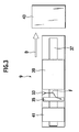
- Fig. 3 is a schematic diagram showing a transmission pathway of an impact load in the front side member of Fig. 1.
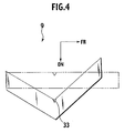
- Fig. 4 is a schematic diagram showing a state where the front side member of Fig. 1 is bent and deformed.
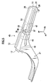
- Fig. 5 is a perspective view of another front side member according to the embodiment of the present invention.
- Fig. 6 is a schematic diagram showing a transmission pathway of an impact load in the front side member of Fig. 5.
- Fig. 7 is a schematic diagram showing a state where the front side member of Fig. 6 is bent and deformed.
-
- An embodiment of the present invention will be explained below with reference to the drawings, wherein like members are designated by like reference characters.
- First of all, a description will be given of a front side member on which a bead for inducing and promoting a bending deformation thereof (hereinafter referred to as a bending deformation promoting bead) and a bead for inducing and promoting an axial deformation or buckling thereof (hereinafter referred to as an axial deformation promoting bead) are formed, and on which a reinforcement panel is arranged corresponding to the bending deformation promoting bead. This front side member can be mounted mainly on a vehicle lighter in weight.
- As shown in Fig. 1, in a front portion of a vehicle body 1, a
cowl box 3 is extended in the vehicle transverse direction.Strut towers 5 are arranged in front of the right and left ends of thecowl box 3, respectively. In addition, across-member 7 is extended in the vehicle transverse direction underneath thecowl box 3. Each ofside members 9 is connected to one of thestrut towers 5 and thecross-member 7. Aflange 13 formed in the rear portion of aclosing plate 11 constituting thefront side member 9 is connected to a transversely inner side face of thestrut tower 5. Aflange 17 at the rear end of a front side membermain body 15 is placed on and fixed to the upper face of thecross-member 7. Furthermore, aflange 19 at the rear end of the transversely inner side face of the front side membermain body 15 is connected to anextension member 21. - As shown in Fig. 2, the
front side member 9 has a closed section structure constituted of the front side membermain body 15 formed in a channel shape (or in U-shape in cross-section) ; and theclosing plate 11 closing an opening of the front side membermain body 15. In addition, the front side membermain body 15 is formed by bending to have: an upwardly extendingupper end flange 23 arranged in the upper end of the front side membermain body 15, anupper wall 25 extending from the lower end of theupper end flange 23 inward in the vehicle transverse direction; aside wall 27 extending downward from a transversely inner edge of theupper wall 25; alower wall 29 extending outward in the vehicle transverse direction form the lower end of theside wall 27; and alower end flange 31 extending downward from a transversely outer edge of thelower wall 29. Theclosing plate 11 is connected at theupper end flange 23 and thelower end flange 31 to the front side membermain body 15. - The
extension member 21 is connected with the rear end of the front side membermain body 15. The rear portion of theextension member 21 is connected with a front floor panel, which is not illustrated. - In a transversely inner and upper corner portion of the front side member
main body 15, almost in the middle of the front side membermain body 15 in the vehicle longitudinal direction, a notch (or a triangle bead) 33 is formed as a bending deformation promoting bead, which is depressed toward the inside of the front side membermain body 15. Furthermore, in a position on the rear side of thenotch 33, arectangular depression 35 is formed as an axial deformation promoting bead extending in a vertical direction across the inner side face of thefront side member 15 and over the top and bottom faces thereof. Aconnection bead 37 is formed on the transversely inner side face of the front side membermain body 15 to extend in the vehicle longitudinal direction or in a direction of transmission of the impact load. Thisconnection bead 37 is formed to cross the axialdeformation promoting bead 35 in a cruciform shape when viewed from the side thereof. - Furthermore, as shown by broken lines in Fig. 2, a
front reinforcement panel 39 and arear reinforcement panel 41, both of which are formed in a channel shape in cross-section, are connected to the back surface (or inside surface) of the front side membermain body 15. Thisfront reinforcement panel 39 is arranged in a position on the front side of thenotch 33 in the vehicle longitudinal direction when viewed from the side thereof. Therear reinforcement panel 41 is arranged in a position on the rear of the axialdeformation promoting bead 35 in the vehicle longitudinal direction when viewed from the side thereof. - A description will be given of a transmission pathway through which an impact load inputted to the
front side member 9 from anobstacle 43 in front of the vehicle is transmitted. - First of all, as shown in Figs. 3 and 4, when the vehicle runs in the traveling direction D and collides against the
obstacle 43, the impact load F is inputted from thisobstacle 43 to thefront side member 9 in an axial direction of thefront side member 9. The front portion of thefront side member 9 is reinforced with thefront reinforcement panel 39. Therefore, the impact load F is transmitted from thenotch 33 to the lower portion of the axialdeformation promoting bead 35 through theconnection bead 37. - Thereafter, as shown by solid lines in Fig. 4, a bending deformation begins at the
notch 33 which is formed to have a low strength and to be a vulnerable part of thefront side member 9. Thefront side member 9 is deformed into V shape with the middle portion thereof bent downward when viewed from the side thereof. In this case, an average reaction force of thefront side member 9 becomes relatively small. The deformation mode of thefront side member 9 is also influenced by a location of the center of gravity of the passenger compartment and the rear part of the vehicle, a shape of the front end portion of the vehicle colliding against theobstacle 43, a point of collision of the vehicle and theobstacle 43, and the like. - Next, a description will be given of a structure of the front side member which absorbs the impact energy by axially deforming (buckling, or collapsing) in the vehicle longitudinal direction at a frontal collision. The same reference numerals are affixed to the same constituent components as the aforementioned structure has, and descriptions for the same constituent components as the aforementioned structure has will be omitted. Incidentally, this front side member can be mounted mainly on a vehicle heavier in weight.
- Another
front side member 45 in Fig. 5 is different from thefront side member 9, which has been described, in the length of and the arrangement position of thefront reinforcement panel 47. - In other words, as shown in Fig. 5, a
rear edge 49 of thefront reinforcement panel 47 is located between the axialdeformation promoting bead 35 and thenotch 33, and afront edge 51 of thefront reinforcement panel 47 is located in a position on the front side of thenotch 33. Thefront reinforcement panel 47 is extended in an area covering thenotch 33 when viewed from the side. All the structures/members other than thefront reinforcement panel 47 are the same as those of the front side member previously described. Thefront side members - A description will be given of a transmission pathway through which an impact load inputted into the
front side member 45 from theobstacle 43 arranged in front of the vehicle is transmitted. - First of all, as shown in Figs. 6 and 7, the impact load F is inputted from the
obstacle 43 to thefront side member 45 in the axial direction of thefront side member 45. Since the front portion of thefront side member 45, including the area of thenotch 33, is reinforced with thefront reinforcement panel 47, the impact load F is transmitted directly to the axialdeformation promoting bead 35 through thefront reinforcement panel 47. - Thereafter, as shown by solid lines in Fig. 7, an axial deformation begins at the axial
deformation promoting bead 35. Thefront side member 45 is deformed in the axial direction thereof with the middle part thereof compressed. In this case, an average reaction force of thefront side member 45 becomes relatively large. - According to the impact energy absorbing structure of the present embodiment, functions and effects which will be described below can be obtained.
- In a case where the
front side member 9 is configured to have a bending deformation beginning at thenotch 33, with thefront reinforcement panel 39 arranged in a position on the front side of thenotch 33 and on the side from which the impact load F is inputted (see Fig. 3). On the other hand, in a case where thefront side member 45 is configured to have an axial deformation beginning at the axialdeformation promoting bead 35, with thefront reinforcement panel 47 extended in an area in thefront side member 45 covering thenotch 33. Therefore, an average reaction force or a deformation mode of thefront side member front reinforcement panels - Specifically, in a case where the
front reinforcement panel 39 is arranged in the position on the front side of thenotch 33 and on the side from which the impact load is inputted, the impact load at the frontal collision is transmitted to the area of thenotch 33 and stress of the impact load concentrates on thenotch 33. Thereby, the bending deformation of thefont side member 9 begins at thenotch 33. On the other hand, in a case where thefront reinforcement panel 47 is arranged in the area in thefront side member 45 covering thenotch 33, the impact load inputted into thefront side member 45 is transmitted to the area of the axialdeformation promoting bead 35. That is because thefront reinforcement panel 47 is superimposed on thenotch 33 so that thefront side member 45 is reinforced and less prone to be bent and deformed around thenotch 33. Accordingly, stress of the impact load concentrates on the axialdeformation promoting bead 35, and thefront side member 45 is deformed with the axialdeformation promoting bead 35 compressed. - In this way, with regard to the
front side members front side members front side members - In addition, the bending deformation promoting bead is provided simply by forming the
notch 33 in the corner portion of thefront side member 9. Therefore, the bending deformation of thefront side member 9 can be easily and surely obtained. - The axial
deformation promoting bead 35 is a bead which is formed on theplanar side wall 27 constituting thefront side members deformation promoting bead 35, and to change the size of the bead. - The
front reinforcement panels front side members front reinforcement panels - Furthermore, the
connection bead 37, serving as the transmission pathway through which the impact load F is transmitted from thenotch 33 to the axialdeformation promoting bead 35, is formed on theplanar side wall 27 constituting thefront side members - The preferred embodiment described herein is illustrative and not restrictive, and the invention may be practiced or embodied in other ways without departing from the spirit or essential character thereof. Although the
notch 33 as the bending deformation promoting bead is formed only in the upper corner portion of each of thefront side members notch 33 may be formed in the lower corner portion of each of thefront side members notch 33 may be formed in both the upper and lower corner portions of each of thefront side members reinforcement panels front side members front side members reinforcement panels - The present disclosure relates to subject matters contained in Japanese Patent Application No. 2004-005517, filed on January 13, 2004, the disclosure of which is expressly incorporated herein by reference in its entirety.
Claims (6)
- An impact energy absorbing structure of a frame member (9; 45) of a vehicle, comprising:wherein the frame member (9; 45) is configured to accommodate the reinforcement panel (39; 47) in a first position beside the first element (33) and on the side from which the impact load (F) is inputted, and in a second position where the first element (33) is reinforced with the reinforcement panel (39; 47).a first element (33) provided on the frame member (9; 45) for promoting bending deformation of the frame member (9; 45) when an impact load (F) is inputted in an axial direction thereof;a second element (35) provided on the frame member (9; 45) for promoting axial deformation of the frame member (9; 45) when the impact load (F) is inputted in the axial direction thereof; anda reinforcement panel (39; 47) attached to the frame member (9; 45),
- The impact energy absorbing structure according to claim 1,
wherein the first element (33) is a notch formed in a corner portion of the frame member (9; 45) extending in the axial direction thereof. - The impact energy absorbing structure according to claim 1,
wherein the second element (35) is a bead formed to extend across a side face of the frame member (9; 45). - The impact energy absorbing structure according to claim 1,
wherein the reinforcement panel (39; 47) is arranged inside the frame member (9; 45). - The impact energy absorbing structure according to claim 1, further comprising:a third element (37) through which the impact load (F) is transmitted from the first element (33) to the second element (35) , the third element (37) being formed on a side face of the frame member (9; 45) to extend in a direction of transmission of the impact load (F).
- A method for controlling a reaction force or a deformation mode of a frame member (9; 45) of a vehicle, the method comprising:providing a first element (33) for promoting bending deformation of the frame member (9; 45) when an impact load (F) is inputted in an axial direction thereof, and a second element (35) for promoting axial deformation of the frame member (9, 45) when the impact load (F) is inputted in the axial direction thereof;providing a reinforcement panel (39; 47) to be accommodated in the frame member (9; 45); andmoving the reinforcement panel (39; 47) on the frame member (9, 45) between a first position beside the first element (33) and on the side from which the impact load (F) is inputted, and a second position where the first element (33) is reinforced with the reinforcement panel (39; 47).
Applications Claiming Priority (2)
| Application Number | Priority Date | Filing Date | Title |
|---|---|---|---|
| JP2004005517 | 2004-01-13 | ||
| JP2004005517A JP3852445B2 (en) | 2004-01-13 | 2004-01-13 | Impact energy absorption structure of member members |
Publications (2)
| Publication Number | Publication Date |
|---|---|
| EP1555191A1 true EP1555191A1 (en) | 2005-07-20 |
| EP1555191B1 EP1555191B1 (en) | 2007-05-30 |
Family
ID=34616839
Family Applications (1)
| Application Number | Title | Priority Date | Filing Date |
|---|---|---|---|
| EP04258176A Expired - Lifetime EP1555191B1 (en) | 2004-01-13 | 2004-12-30 | Impact energy absorbing structure of vehicle frame member |
Country Status (5)
| Country | Link |
|---|---|
| US (1) | US7097235B2 (en) |
| EP (1) | EP1555191B1 (en) |
| JP (1) | JP3852445B2 (en) |
| CN (1) | CN100366491C (en) |
| DE (1) | DE602004006707T2 (en) |
Cited By (6)
| Publication number | Priority date | Publication date | Assignee | Title |
|---|---|---|---|---|
| US7114763B2 (en) | 2001-11-14 | 2006-10-03 | L & L Products, Inc. | Automotive rail/frame energy management system |
| US7194804B2 (en) | 1999-12-10 | 2007-03-27 | L & L Products, Inc. | Method of forming a hydroform |
| FR2921622A1 (en) * | 2007-09-27 | 2009-04-03 | Renault Sas | Side rail element for chassis of motor vehicle, has fixation unit comprising walls for fixing cylindrical tube in side rail element to locally reinforce resistance of side rail element to axial compression |
| DE102008047695A1 (en) | 2008-09-18 | 2010-03-25 | GM Global Technology Operations, Inc., Detroit | Body part for motor vehicle, has front frame arranged in travel direction of motor vehicle before front wall, where shank of central front frame profile is mounted with basis of forward front frame profile |
| US7735906B2 (en) | 2007-09-28 | 2010-06-15 | Zephyros, Inc. | Reinforcement system for an automotive vehicle |
| US20150175208A1 (en) * | 2012-06-04 | 2015-06-25 | Nippon Steel & Sumitomo Metal Corporation | Vehicle frame member structure with excellent impact resistance performance |
Families Citing this family (44)
| Publication number | Priority date | Publication date | Assignee | Title |
|---|---|---|---|---|
| EP1653114B2 (en) * | 2003-07-28 | 2015-06-03 | Nippon Steel & Sumitomo Metal Corporation | Impact-absorbing member |
| US7380830B2 (en) * | 2005-02-03 | 2008-06-03 | Honda Motor Co., Ltd. | Vehicle front body structure |
| US7699346B2 (en) * | 2005-03-23 | 2010-04-20 | Chrysler Group Llc | Force redistributing system for a vehicle in the event of a rear impact |
| JP4394032B2 (en) * | 2005-04-15 | 2010-01-06 | 本田技研工業株式会社 | Body front structure |
| JP4969827B2 (en) * | 2005-10-19 | 2012-07-04 | 富士重工業株式会社 | Body front structure |
| DE102006036455A1 (en) * | 2006-08-04 | 2008-02-07 | GM Global Technology Operations, Inc., Detroit | New front frame concept for body construction on a multiple platform |
| JP4301269B2 (en) | 2006-09-06 | 2009-07-22 | 日産自動車株式会社 | Member member for vehicle |
| JP5092323B2 (en) * | 2006-09-08 | 2012-12-05 | 株式会社日立製作所 | Rail vehicle |
| US7677649B2 (en) * | 2007-01-11 | 2010-03-16 | Ford Motor Company | Vehicle having an interlocking floor assembly |
| US8317964B2 (en) * | 2007-01-11 | 2012-11-27 | Ford Motor Company | Method of manufacturing a vehicle |
| US7591502B2 (en) * | 2007-01-11 | 2009-09-22 | Ford Motor Company | Tunable inner fender structure |
| US7849601B2 (en) * | 2007-01-11 | 2010-12-14 | Ford Motor Company | Method of manufacturing a vehicle |
| US8123284B2 (en) * | 2007-01-11 | 2012-02-28 | Ford Motor Company | Vehicle body component and mating feature |
| US7798560B2 (en) * | 2007-01-11 | 2010-09-21 | Ford Motor Company | Vehicle body structure |
| JP4998097B2 (en) * | 2007-06-07 | 2012-08-15 | マツダ株式会社 | Energy absorbing member |
| JP2009234495A (en) * | 2008-03-28 | 2009-10-15 | Mazda Motor Corp | Frame structure of automobile |
| US8210601B2 (en) * | 2008-09-18 | 2012-07-03 | Mazda Motor Corporation | Vehicle body structure |
| JP5246139B2 (en) * | 2009-02-26 | 2013-07-24 | トヨタ自動車株式会社 | Vehicle front structure |
| DE102009031782A1 (en) * | 2009-07-06 | 2011-01-13 | GM Global Technology Operations, Inc., Detroit | Motor vehicle front end |
| DE102009041771A1 (en) * | 2009-09-16 | 2011-03-17 | Volkswagen Ag | Subframe for a motor vehicle |
| JP2011178179A (en) * | 2010-02-26 | 2011-09-15 | Nisshin Steel Co Ltd | Structural member having superior impact absorbing characteristic |
| JP5228013B2 (en) * | 2010-09-14 | 2013-07-03 | 本田技研工業株式会社 | Body front structure |
| US8752295B2 (en) * | 2010-12-29 | 2014-06-17 | GM Global Technology Operations LLC | Method of varying material properties |
| CN102229348B (en) * | 2011-02-12 | 2012-12-19 | 广州汽车集团股份有限公司 | Front longitudinal beam and geometric energy absorbing control structure as well as automobile and method for providing geometric energy absorbing control structure |
| JP5427216B2 (en) * | 2011-09-27 | 2014-02-26 | 本田技研工業株式会社 | Light load absorption structure |
| CN103796905A (en) | 2011-10-25 | 2014-05-14 | 丰田自动车株式会社 | Skeleton components |
| US8708401B2 (en) * | 2012-03-22 | 2014-04-29 | Ford Global Technologies, Llc | Crash brace for energy management |
| FR2989054B1 (en) | 2012-04-05 | 2014-03-21 | Renault Sa | AUTOMOTIVE VEHICLE CHASSIS OPTIMIZED FOR THE ABSORPTION OF A FRONTAL SHOCK |
| DE102012111671A1 (en) * | 2012-11-30 | 2014-06-05 | Dr. Ing. H.C. F. Porsche Aktiengesellschaft | Reinforcement carrier for installation in longitudinal beam of front end of motor vehicle, is formed as square tube, and has corrugation at its front end area, where corrugation bates side wall of square tube |
| KR101526420B1 (en) * | 2013-12-16 | 2015-06-05 | 현대자동차 주식회사 | Discontinuous multi-overlapped vehicle body member |
| US9381949B2 (en) * | 2014-10-15 | 2016-07-05 | Toyota Motor Engineering & Manufacturing North America, Inc. | Vehicles having a cross-vehicle stabilizing structure |
| US9260138B1 (en) | 2014-10-21 | 2016-02-16 | Toyota Motor Engineering & Manufacturing North America, Inc. | Vehicles having a cross-vehicle stabilizing structure |
| CN104828143B (en) * | 2014-12-04 | 2017-02-01 | 北汽福田汽车股份有限公司 | collision energy-absorbing longitudinal beam and frame |
| JP6107850B2 (en) * | 2015-02-27 | 2017-04-05 | マツダ株式会社 | Vehicle frame structure |
| JP6464914B2 (en) * | 2015-05-12 | 2019-02-06 | 日産自動車株式会社 | Engine mount structure |
| US9643651B2 (en) | 2015-08-28 | 2017-05-09 | Honda Motor Co., Ltd. | Casting, hollow interconnecting member for connecting vehicular frame members, and vehicular frame assembly including hollow interconnecting member |
| DE102016006848B4 (en) * | 2016-06-04 | 2025-07-24 | Audi Ag | Axle carrier for a multi-track vehicle |
| CN109496191B (en) | 2016-07-21 | 2021-01-08 | 本田技研工业株式会社 | Front body structure |
| IT201600101007A1 (en) * | 2016-10-07 | 2018-04-07 | P Gevs S R L | ELECTRIC TRACTION MOTOR VEHICLE, AND ITS APPLICATION METHOD |
| US10214243B2 (en) * | 2017-07-11 | 2019-02-26 | Ford Global Technologies, Llc | Vehicle frame |
| JP6568569B2 (en) * | 2017-12-01 | 2019-08-28 | 本田技研工業株式会社 | Body front structure |
| JP7047479B2 (en) * | 2018-03-09 | 2022-04-05 | トヨタ自動車株式会社 | Vehicle undercarriage |
| US12434770B1 (en) * | 2024-12-06 | 2025-10-07 | Fca Us Llc | Vehicle frame having asymmetric bead structure for high voltage component protection |
| US12503167B1 (en) * | 2025-02-28 | 2025-12-23 | Fca Us Llc | Vehicle frame designed for high voltage component protection in frontal impacts |
Citations (4)
| Publication number | Priority date | Publication date | Assignee | Title |
|---|---|---|---|---|
| EP0878379A1 (en) * | 1996-02-09 | 1998-11-18 | Toyota Jidosha Kabushiki Kaisha | Front structure of car body, and method of absorbing impact by means of the front structure |
| JP2000185611A (en) * | 1998-12-24 | 2000-07-04 | Toyota Motor Corp | Impact energy absorbing structure on top of car body |
| US20010013705A1 (en) * | 2000-02-15 | 2001-08-16 | G P Daikyo Corporation | Impact absorbing mechanism and bumper reinforcement having the mechanism |
| US20010019214A1 (en) * | 1997-06-18 | 2001-09-06 | Toyota Jidosha Kabushiki Kaisha | Automotive impact energy absorbing structure |
Family Cites Families (15)
| Publication number | Priority date | Publication date | Assignee | Title |
|---|---|---|---|---|
| DE2636655A1 (en) * | 1976-08-14 | 1978-02-16 | Daimler Benz Ag | HOLLOW BEAM FOR VEHICLES AND METHOD FOR ITS MANUFACTURING |
| US4684151A (en) * | 1986-03-21 | 1987-08-04 | General Motors Corporation | Controlled collapsible frame rail |
| JPS6364883A (en) * | 1986-09-04 | 1988-03-23 | Mazda Motor Corp | Structure for front frame of automobile |
| JP2595724B2 (en) * | 1989-08-30 | 1997-04-02 | 日産自動車株式会社 | Manufacturing method of strength member |
| JPH0450083A (en) * | 1990-06-15 | 1992-02-19 | Toyota Motor Corp | Front side member structure for car body |
| US5370438A (en) * | 1991-10-31 | 1994-12-06 | Toyota Jidosha Kabushiki Kaisha | Structural member of automobile |
| JP3000898B2 (en) * | 1995-07-12 | 2000-01-17 | トヨタ自動車株式会社 | Impact energy absorbing structure of automobile |
| JP3394142B2 (en) * | 1996-10-25 | 2003-04-07 | 富士重工業株式会社 | Frame structure of vehicle body |
| JP3480226B2 (en) | 1997-03-06 | 2003-12-15 | トヨタ自動車株式会社 | Front side member collision energy absorption structure |
| US6655728B2 (en) * | 2000-04-25 | 2003-12-02 | Nissan Motor Co., Ltd. | Body structure of vehicle |
| FR2809072B1 (en) * | 2000-05-19 | 2002-11-01 | Renault | BODY STRUCTURE ASSEMBLY COMPRISING LONGERS PROVIDED WITH FOLDING PRIMER AREAS |
| US6942262B2 (en) * | 2001-09-27 | 2005-09-13 | Shape Corporation | Tubular energy management system for absorbing impact energy |
| US6820924B2 (en) * | 2003-01-13 | 2004-11-23 | Ford Global Technologies, Llc | Method of improving impact absorbing and deformation control characteristics of vehicle components |
| JP2005162188A (en) * | 2003-09-25 | 2005-06-23 | Nissan Motor Co Ltd | Body structure |
| JP3970831B2 (en) * | 2003-10-16 | 2007-09-05 | 本田技研工業株式会社 | Auto body structure |
-
2004
- 2004-01-13 JP JP2004005517A patent/JP3852445B2/en not_active Expired - Lifetime
- 2004-12-30 EP EP04258176A patent/EP1555191B1/en not_active Expired - Lifetime
- 2004-12-30 DE DE602004006707T patent/DE602004006707T2/en not_active Expired - Lifetime
-
2005
- 2005-01-05 US US11/028,516 patent/US7097235B2/en not_active Expired - Lifetime
- 2005-01-13 CN CNB200510004353XA patent/CN100366491C/en not_active Expired - Lifetime
Patent Citations (5)
| Publication number | Priority date | Publication date | Assignee | Title |
|---|---|---|---|---|
| EP0878379A1 (en) * | 1996-02-09 | 1998-11-18 | Toyota Jidosha Kabushiki Kaisha | Front structure of car body, and method of absorbing impact by means of the front structure |
| US20010019214A1 (en) * | 1997-06-18 | 2001-09-06 | Toyota Jidosha Kabushiki Kaisha | Automotive impact energy absorbing structure |
| US20010019215A1 (en) * | 1997-06-18 | 2001-09-06 | Toyota Jidosha Kabushiki Kaisha | Automotive impact energy absorbing structure |
| JP2000185611A (en) * | 1998-12-24 | 2000-07-04 | Toyota Motor Corp | Impact energy absorbing structure on top of car body |
| US20010013705A1 (en) * | 2000-02-15 | 2001-08-16 | G P Daikyo Corporation | Impact absorbing mechanism and bumper reinforcement having the mechanism |
Non-Patent Citations (1)
| Title |
|---|
| PATENT ABSTRACTS OF JAPAN vol. 2000, no. 10 17 November 2000 (2000-11-17) * |
Cited By (7)
| Publication number | Priority date | Publication date | Assignee | Title |
|---|---|---|---|---|
| US7194804B2 (en) | 1999-12-10 | 2007-03-27 | L & L Products, Inc. | Method of forming a hydroform |
| US7114763B2 (en) | 2001-11-14 | 2006-10-03 | L & L Products, Inc. | Automotive rail/frame energy management system |
| FR2921622A1 (en) * | 2007-09-27 | 2009-04-03 | Renault Sas | Side rail element for chassis of motor vehicle, has fixation unit comprising walls for fixing cylindrical tube in side rail element to locally reinforce resistance of side rail element to axial compression |
| US7735906B2 (en) | 2007-09-28 | 2010-06-15 | Zephyros, Inc. | Reinforcement system for an automotive vehicle |
| DE102008047695A1 (en) | 2008-09-18 | 2010-03-25 | GM Global Technology Operations, Inc., Detroit | Body part for motor vehicle, has front frame arranged in travel direction of motor vehicle before front wall, where shank of central front frame profile is mounted with basis of forward front frame profile |
| US20150175208A1 (en) * | 2012-06-04 | 2015-06-25 | Nippon Steel & Sumitomo Metal Corporation | Vehicle frame member structure with excellent impact resistance performance |
| US9205870B2 (en) * | 2012-06-04 | 2015-12-08 | Nippon Steel & Sumitomo Metal Corporation | Vehicle frame member structure with excellent impact resistance performance |
Also Published As
| Publication number | Publication date |
|---|---|
| JP3852445B2 (en) | 2006-11-29 |
| EP1555191B1 (en) | 2007-05-30 |
| US20050151392A1 (en) | 2005-07-14 |
| CN1640745A (en) | 2005-07-20 |
| CN100366491C (en) | 2008-02-06 |
| DE602004006707D1 (en) | 2007-07-12 |
| DE602004006707T2 (en) | 2008-01-24 |
| JP2005199751A (en) | 2005-07-28 |
| US7097235B2 (en) | 2006-08-29 |
Similar Documents
| Publication | Publication Date | Title |
|---|---|---|
| US7097235B2 (en) | Impact energy absorbing structure of vehicle frame member | |
| EP2105373B1 (en) | Frame structure for automotive vehicle and method of providing the same | |
| US7147272B2 (en) | Vehicle body floor structure | |
| US7185934B2 (en) | Vehicle body structure | |
| CA2853708C (en) | Subframe with beads | |
| CN109204527B (en) | Body Structure and Vehicle | |
| JP3254629B2 (en) | Reinforcement structure for sill side of automobile | |
| US7731272B2 (en) | A-pillar force transfer structure | |
| JP5881131B2 (en) | Auto body structure | |
| CN111284564A (en) | Vehicle body structure | |
| CN111284567A (en) | body structure | |
| JP4534681B2 (en) | Vehicle rear body structure | |
| JP2014136436A (en) | Automotive vehicle body structure | |
| CN109204502B (en) | Body Structure and Vehicle | |
| JP6418204B2 (en) | Front body structure of the vehicle | |
| JP2004050865A (en) | Vehicle fender structure | |
| JP2003063454A (en) | Car body front structure | |
| US7165805B2 (en) | Vehicle front body structure | |
| CN109204508B (en) | Body Structure and Vehicle | |
| JP2017140874A (en) | Side part car body structure of vehicle | |
| CN115397721A (en) | Motor vehicle with front pillar reinforcement for low-footprint frontal collision | |
| CN109204467B (en) | Body Structure and Vehicle | |
| CN219883953U (en) | Heavy truck front cabin frame structure and vehicle | |
| JP4496956B2 (en) | Body front structure | |
| JP4394894B2 (en) | Rear floor structure |
Legal Events
| Date | Code | Title | Description |
|---|---|---|---|
| PUAI | Public reference made under article 153(3) epc to a published international application that has entered the european phase |
Free format text: ORIGINAL CODE: 0009012 |
|
| 17P | Request for examination filed |
Effective date: 20050124 |
|
| AK | Designated contracting states |
Kind code of ref document: A1 Designated state(s): AT BE BG CH CY CZ DE DK EE ES FI FR GB GR HU IE IS IT LI LT LU MC NL PL PT RO SE SI SK TR |
|
| AX | Request for extension of the european patent |
Extension state: AL BA HR LV MK YU |
|
| AKX | Designation fees paid |
Designated state(s): DE GB |
|
| GRAP | Despatch of communication of intention to grant a patent |
Free format text: ORIGINAL CODE: EPIDOSNIGR1 |
|
| GRAS | Grant fee paid |
Free format text: ORIGINAL CODE: EPIDOSNIGR3 |
|
| GRAA | (expected) grant |
Free format text: ORIGINAL CODE: 0009210 |
|
| AK | Designated contracting states |
Kind code of ref document: B1 Designated state(s): DE GB |
|
| REG | Reference to a national code |
Ref country code: GB Ref legal event code: FG4D |
|
| RIN1 | Information on inventor provided before grant (corrected) |
Inventor name: YASUKOUCHI, SATOSHI Inventor name: TACHIZAWA, HIROYUKI |
|
| REF | Corresponds to: |
Ref document number: 602004006707 Country of ref document: DE Date of ref document: 20070712 Kind code of ref document: P |
|
| PLBE | No opposition filed within time limit |
Free format text: ORIGINAL CODE: 0009261 |
|
| STAA | Information on the status of an ep patent application or granted ep patent |
Free format text: STATUS: NO OPPOSITION FILED WITHIN TIME LIMIT |
|
| 26N | No opposition filed |
Effective date: 20080303 |
|
| REG | Reference to a national code |
Ref country code: DE Ref legal event code: R084 Ref document number: 602004006707 Country of ref document: DE |
|
| REG | Reference to a national code |
Ref country code: GB Ref legal event code: 746 Effective date: 20231002 |
|
| PGFP | Annual fee paid to national office [announced via postgrant information from national office to epo] |
Ref country code: GB Payment date: 20231121 Year of fee payment: 20 |
|
| PGFP | Annual fee paid to national office [announced via postgrant information from national office to epo] |
Ref country code: DE Payment date: 20231121 Year of fee payment: 20 |
|
| REG | Reference to a national code |
Ref country code: DE Ref legal event code: R071 Ref document number: 602004006707 Country of ref document: DE |
|
| PG25 | Lapsed in a contracting state [announced via postgrant information from national office to epo] |
Ref country code: GB Free format text: LAPSE BECAUSE OF EXPIRATION OF PROTECTION Effective date: 20241229 |
|
| REG | Reference to a national code |
Ref country code: GB Ref legal event code: PE20 Expiry date: 20241229 |
|
| PG25 | Lapsed in a contracting state [announced via postgrant information from national office to epo] |
Ref country code: GB Free format text: LAPSE BECAUSE OF EXPIRATION OF PROTECTION Effective date: 20241229 |