EP1555154B1 - Filler tube for the filling of fuel in a vehicle tank - Google Patents
Filler tube for the filling of fuel in a vehicle tank Download PDFInfo
- Publication number
- EP1555154B1 EP1555154B1 EP04018518A EP04018518A EP1555154B1 EP 1555154 B1 EP1555154 B1 EP 1555154B1 EP 04018518 A EP04018518 A EP 04018518A EP 04018518 A EP04018518 A EP 04018518A EP 1555154 B1 EP1555154 B1 EP 1555154B1
- Authority
- EP
- European Patent Office
- Prior art keywords
- actuating
- ring
- actuating ring
- filler neck
- closing
- Prior art date
- Legal status (The legal status is an assumption and is not a legal conclusion. Google has not performed a legal analysis and makes no representation as to the accuracy of the status listed.)
- Expired - Fee Related
Links
Images


Classifications
-
- B—PERFORMING OPERATIONS; TRANSPORTING
- B60—VEHICLES IN GENERAL
- B60K—ARRANGEMENT OR MOUNTING OF PROPULSION UNITS OR OF TRANSMISSIONS IN VEHICLES; ARRANGEMENT OR MOUNTING OF PLURAL DIVERSE PRIME-MOVERS IN VEHICLES; AUXILIARY DRIVES FOR VEHICLES; INSTRUMENTATION OR DASHBOARDS FOR VEHICLES; ARRANGEMENTS IN CONNECTION WITH COOLING, AIR INTAKE, GAS EXHAUST OR FUEL SUPPLY OF PROPULSION UNITS IN VEHICLES
- B60K15/00—Arrangement in connection with fuel supply of combustion engines or other fuel consuming energy converters, e.g. fuel cells; Mounting or construction of fuel tanks
- B60K15/03—Fuel tanks
- B60K15/04—Tank inlets
- B60K2015/0458—Details of the tank inlet
- B60K2015/0483—Means to inhibit the introduction of too small or too big filler nozzles
Definitions
- the invention relates to a filler neck for the filling of fuel in a vehicle tank according to claim 1.
- filler neck for diesel fuel have become known, which are designed so that when inserting a diesel fuel nozzle, a filling valve opens.
- the valve When inserting a fuel nozzle, however, the valve is either not operated, so that the gasoline in the front Area of the filler neck remains or there is such a strong restriction that the fuel nozzle switches off automatically.
- the nozzles contain a mechanism that locks the valve in the fuel nozzle as soon as a certain back pressure builds up. This is primarily avoided that it comes to an overfilling of the tank.
- the known filler neck require a relatively large amount of space and are relatively expensive. In addition, they are not suitable for so-called capless filling systems. These are filling systems that enable automatic refueling.
- the filler neck is no longer completed by a special cap, but the fuel nozzle can be easily introduced.
- it has become known from FR 2761934 to provide a closure cap at the end of a filler neck. It opens inwards and is provided with a seal which cooperates with a sealing edge in the interior of the nozzle.
- the invention has for its object to provide a filler neck for the filling of diesel fuel in a vehicle tank, which requires little space and components to prevent misfuelling, and which is also suitable to be used in conjunction with capless filling systems and protection against the ingress of unwanted media into the tank.
- an actuating ring which consists of resilient material and / or biased by a spring radially inwardly and is divided over a preferably axially parallel gap.
- the actuating ring has a conically narrowing insertion section.
- the throat cross section of the insertion section is smaller than the cross section of a diesel nozzle and is equal to or greater than the cross section of a gasoline fuel nozzle. In other words, the diesel nozzle can not easily be passed through the throat section, which is possible for the gasoline nozzle.
- the actuating ring has at the end facing the tank on at least one side of the gap an actuating portion.
- the actuating ring is arranged floating in a preferably pot-shaped housing, i.
- the outer diameter of the actuating ring in the relaxed state is smaller than the inner dimensions of the housing.
- the tank-side end of the actuating ring is associated with a closure mechanism which is designed so that it constitutes a stop in the closed position for an inserted fuel nozzle. Therefore, if an Ottozpfpistole is introduced in the invention, this may pass the actuating ring readily, but abuts against the shutter mechanism and therefore can not be further introduced. This can easily be determined by the person who wants to fill up the tank so that it can correct the mistake. Unless the error is noted, opening the fuel nozzle would result in immediate closure of the valve in the fuel nozzle, as there is instantaneous flow congestion due to the shutter mechanism. The shutter mechanism does not have to close the passage tight. Sufficient throttling of the fuel flow is sufficient for its function.
- the solution of claim 2 serves the application of the invention to a capless filler neck.
- the shutter mechanism has a movable shutter member which seals the passage substantially.
- a transmission which is necessary to translate the movement of the actuating portion of the actuating ring when inserting a fuel nozzle into an opening movement of the shutter mechanism, can be conceived as simple as possible in the invention. A favorable embodiment of this will be explained below. Since the actuating ring is mounted floating, the ring is not widened when inserting a nozzle with smaller outer diameter, but lets the fuel nozzle pass easily. The shutter mechanism then remains in the closed position.
- the closure mechanism is preferably designed such that the passage to the tank is largely sealed.
- the filler neck according to the invention acts as protection against ingress of dust, foreign bodies, dirty water, etc., when a cap is not provided.
- the conical insertion section is formed in the actuating ring of radial circumferentially spaced ribs or fins.
- the ribs or fins prevent expansion of the actuating ring due z. B. of spray under pressure.
- the actuating ring can be integrally molded from plastic, which embodies sufficient spring properties.
- an annular spring may surround the actuating ring which biases the actuating ring radially inwardly.
- the closure mechanism has a closure flap, with which a side arm is connected, which is pivotally mounted about an axis and which extends approximately parallel to the axis of the cup-shaped housing.
- the arm has a slot in which engages the first actuating portion of the actuating ring, while a second actuating portion is limitedly movable in a slightly larger stationary recess.
- the confirmation sections on pins wherein a pin engages in a slot of the closure flap and the other pin in a hole of a bearing component.
- the bearing flap bearing bearing member may be formed by a fixedly mounted bearing ring having a through hole for the tank filling, which is approximately coaxial with the closure flap in the closed position.
- the bearing ring further comprises an arcuate slot through which a mounting pin is passed for engagement in the slot of the arm - the closure flap.
- the inventive design of a filler neck for fuel is also suitable for capless filler neck, because on the one hand there is a faulty operation and on the other by the flap sufficient protection is ensured against the ingress of foreign bodies, impurities, etc. in the tank of the motor vehicle.
- the closure mechanism on a closure flap which is about an axis transverse to the axis of the actuating ring is pivotally mounted. It is preferably mounted on the actuating ring itself, and this has an operating portion in the region of the gap, which engages over a radial projection or projection of the closure flap when it is in the closed position.
- a spring biases the closure flap in this closed position. While opening the closure mechanism via a fuel nozzle, the flap must also be pivoted against a spring preload, but the spring preload can be kept very small. It must be sufficient to adjust the flap in the Verschoudregna. It does not have to withstand greater forces, for example spray water pressure, because the flap is locked in the closed position via the actuating portion of the actuating ring.
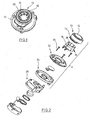
- a pot-shaped housing 10 having an entry port 12 at one end and a lateral extension 14 at the other end. The other end is facing the tank, not shown, of an automobile.
- an actuating ring 16 is shown, which is divided at 18.
- a tab 20 or 22 integrally formed, which projects approximately radially and which has a pin 24 and 26 respectively at the bottom.
- the pins 24, 26 extend axially parallel.
- a plurality of radial ribs 28 are provided, which are arranged at uniform circumferential intervals.
- the ribs form an insertion section which narrows away from the cup-shaped housing 10.
- the actuating ring 16 is inserted into the cup-shaped housing 10. In the relaxed state, the outer diameter of the actuating ring 16 is significantly smaller than the inner diameter of the pot-shaped housing 10th
- a bearing ring 32 is screwed to a mating ring 34, at the same time there is a screw with a housing 36 which includes a not shown capless filling system, which will not be discussed in detail.
- a capless filling system which will not be discussed in detail.
- Such a system has already been explained above by reference to a French document. It allows the introduction of a nozzle by opening a flap automatically by the nozzle opens the flap and opens the way for the fuel. This part is shown in Fig. 2 to the left of Group 3. However, it should not be described in detail.
- a closure flap 38 is shown between the rings 32, 34. It has an approximately circular closure plate 40, a radial arm 42 and a bearing eye 44.
- the bearing eye acts with an axis-parallel pin 46 on the closure flap 38 facing Side of the bearing ring 32 together.
- the bearing ring has a through hole 48 which is aligned with the opening 12 approximately axially and is also coaxial with an opening 50 in the ring 34th
- an arcuate slot 52 is formed, through which the pin 26 extends.
- An approximately radial slot 54 receives the second pin 24.
- the pin 26 engages in a radial elongated slot 56 of the arm 42.
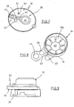
- Fig. 4 can be seen the counter-bearing ring 34 which is connectable to the housing 36 by the screw (not shown).
- the closure plate 40 which closes the opening 50 (Fig. 3), wherein the bearing eye 44 cooperates with an axis-parallel pin 58 of the ring 34.
- the pin 58 is hollow for receiving the pin 46 of the bearing ring 32nd
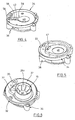
- Fig. 5 it is shown how with the counter-bearing ring 34 and the closure flap 38 of the bearing ring 32 is composed.
- Fig. 6 it is shown how additionally the actuating ring 16 is placed on the bearing ring 32.
- the actuating ring 16 no ribs, but sector-shaped lamellae 28a, which together form a tapered to the tank insertion section.
- a narrow section is given as 60.
- the diameter of the narrow section is slightly larger than the diameter for the Ottozpfpistole, but significantly smaller than the diameter of the diesel nozzle. Therefore, if a diesel nozzle is inserted into the actuator ring, it must widen the actuator ring 16 to continue to be driven. As a result, the gap 18 increases and the tabs 20, 22 are moved apart.
- Fig. 7 the tank facing side of the bearing ring 32 is shown with the flap 38. It can be seen how the actuating pin 26 extends through the arcuate slot 52 of the bearing ring 32 in engagement with the slot 56. The second pin 24 is located in the elongated slot 54. Therefore, a moving apart of the pins 24, 26 leads to a pivoting of the closure flap 38th in the clockwise direction, whereby the through hole 48 of the bearing ring 32 is opened. As a result, the fuel nozzle can be further demonstrated in the direction of the tank for actuating the filling system, which is located in the housing 36.
- the rings 32, 34 and housing 36 are screwed together via the screws 30.
- the attachment of the housing 36 to the body is not shown in detail.
- the attachment of the cup-shaped housing 10, which receives the actuating ring 16, on the bearing ring 32 is not shown.
- a screw fastening, gluing or the like can be made.
- the remaining parts of the illustrated filler neck can be made of a suitable plastic material.
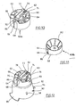
- an actuating ring 60a can be seen, which is constructed similarly to the actuating ring 16 according to the preceding figures. It has on the inside a number of spaced apart by a slot slats 62, which form a tapered in Fig. 11 from top to bottom inlet portion for a fuel gun, not shown.
- the actuating ring 60a is divided by an axially parallel gap 64, and on each side of the gap 64, the ring has axially parallel lugs 66, 68 having opposite cuts.
- an incision is designated 70.
- the actuating ring 60a On the side opposite to the gap 64, the actuating ring 60a has two circumferentially spaced bearing lugs 72, 74.
- a closure flap 76 is provided with a fork-shaped radial projection 78 which is pivotally mounted by means of a bearing pin 80 in the bearing lugs 72, 74.
- Within the fork-shaped projection 78 is a coil spring 82 with an extended leg 84 at one end, which abuts against the top of the flap 76. As a result, the closure flap 76 is biased into the closed position.
- a radial projection 86 is formed on the closure flap 76. It engages laterally in the opposite recesses 70 of the lugs 66, 68. As a result, the closure flap 76 is locked in the closed position shown in Fig. 10.
- a conical annular body or insert 90 is shown, which widens in Fig. 12 from top to bottom.
- the actuating ring 60a is placed on the upwardly facing end face 92.
- the conical insert 90 has two radial flanges 94, 96.
- the conical insert 90 on its outer side at intervals locking lugs 98.
- a cup-shaped housing 100 is shown, which has a lower conical housing part 102 and a cylindrical adjoining thereto at the top Housing part 104 has.
- the housing part 104 is provided with a bottom 106 which has an opening 108 through which the actuating ring 60a with closure flap 76 can be seen.
- the cup-shaped housing 100 is externally circumferentially provided with reinforcing ribs 110 and formed at the lower end with two diametrically opposed flanges 112, 114 at the bottom in Fig. 13. In the conical housing part 102 also locking openings 112a can be seen.
- the actuating ring 60a is placed against the bottom 106 of the housing 100 from inside, as can be seen in Fig. 14, with space between the outside of the ring 60a and the inside of the housing part 104 so that the actuating ring 60a is limited laterally inside the housing Can move housing 104.
- the conical insert 90 is then inserted into the housing 100, wherein the outer dimensions of the conical insert 90 correspond approximately to the inner dimensions of the housing part 102 and the locking lugs 98 engage in the locking holes 112 a, as shown in Fig. 13.
- the flanges 94, 96 of the conical insert 90 engage in the gaps of the flanges 112, 114 approximately fitting, so that a complete circle is formed.
- the insert 90 is thus fixed in the housing 100 and secures in turn axially the actuating ring 60a in the housing 100.
- the actuating ring as mentioned, but can move radially limited.
Description
Die Erfindung bezieht sich auf einen Einfüllstutzen für das Einfüllen von Kraftstoff in einen Fahrzeugtank nach dem Patentanspruch 1.The invention relates to a filler neck for the filling of fuel in a vehicle tank according to claim 1.
Es ist bekannt, Zapfpistolen für Ottokraftstoff einerseits und Dieselkraftstoff andererseits mit einem unterschiedlichen Durchmesser zu versehen. Diese Maßnahme wurde eingeführt, nachdem bleifreier Ottokraftstoff von verbleitem Kraftstoff unterschieden werden mußte. Die Zapfpistolen für bleifreien Ottokraftstoff haben einen kleineren Außendurchmesser als die Zapfpistolen für verbleiten Kraftstoff und für Dieselkraftstoff. Eine Falschbetankung eines Dieselfahrzeugs mit Ottokraftstoff ist jedoch nicht ausgeschlossen, wenn nicht besondere Vorkehrungen hierfür getroffen werden. Aus DE 101 26 207, die den Oberbegriff des Anspruchs 1 definiert, ist bekannt geworden, eine um eine Querachse verschwenkbare Klappe im Einführweg der Zapfpistole im geschlossenen Zustand zu verriegeln. Die Verriegelung wird gebildet von mehreren radial angeordneten, im Umfangsabstand angeordneten Sperrhaken, die in einem elastischen Ring gelagert wird und die einen konischen Einführabschnitt bilden. Wird eine Ottozapfpistole eingeführt, bleiben die Sperrhaken in ihrem Ruhezustand und die Zapfpistole stößt gegen die verriegelte Klappe. Die Dieselzapfpistole hingegen verstellt die Sperrhaken radial und entriegelt dadurch die Klappe, so daß die Zapfpistole die Klappe öffnen kann. Eine Fehlbetankung durch Manipulation mit der Ottozapfpistole, durch welche die Verriegelung aufgehoben wird, ist nicht ausgeschlossen.It is known to provide fuel nozzles for gasoline on the one hand and diesel fuel on the other hand with a different diameter. This measure was introduced after unleaded petrol had to be differentiated from leaded fuel. The fuel nozzles for unleaded petrol have a smaller outside diameter than the leaded fuel and diesel fuel nozzles. However, misfuelling a diesel vehicle with petrol is not excluded unless special precautions are taken. From DE 101 26 207, which defines the preamble of claim 1, it has become known to lock a pivotable about a transverse axis flap in the insertion of the fuel nozzle in the closed state. The lock is formed by a plurality of radially arranged, circumferentially spaced pawl, which is mounted in an elastic ring and which form a conical insertion section. If an Ottozpfpole introduced, the pawls remain in their idle state and the fuel nozzle pushes against the locked flap. The diesel fuel nozzle, however, displaces the pawls radially and thereby unlocks the flap, so that the fuel nozzle can open the flap. A misfuel by manipulation with the fuel nozzle, through which the lock is released, is not excluded.
Aus DE 101 39 665 und DE 101 26 209 sind Einfüllstutzen für Dieselkraftstoff bekannt geworden, die so ausgeführt sind, daß beim Einführen einer Dieselzapfpistole ein Einfüllventil öffnet. Beim Einführen einer Ottozapfpistole wird hingegen das Ventil entweder nicht betätigt, so daß der Ottokraftstoff im vorderen Bereich des Einfüllstutzens verbleibt oder es erfolgt eine derartige starke Drosselung, daß sich die Zapfpistole automatisch abschaltet. Bekanntlich enthalten die Zapfpistolen einen Mechanismus, der das Ventil in der Zapfpistole sperrt, sobald sich ein gewisser Staudruck aufbaut. Dadurch wird in erster Linie vermieden, daß es zu einer Überfüllung des Tanks kommt.From DE 101 39 665 and DE 101 26 209 filler neck for diesel fuel have become known, which are designed so that when inserting a diesel fuel nozzle, a filling valve opens. When inserting a fuel nozzle, however, the valve is either not operated, so that the gasoline in the front Area of the filler neck remains or there is such a strong restriction that the fuel nozzle switches off automatically. As is known, the nozzles contain a mechanism that locks the valve in the fuel nozzle as soon as a certain back pressure builds up. This is primarily avoided that it comes to an overfilling of the tank.
Die bekannten Einfüllstutzen benötigen relativ viel Bauraum und sind relativ aufwendig. Außerdem sind sie nicht für sogenannte kappenlose Einfüllsysteme verwendbar. Hierunter versteht man Einfüllsysteme, die eine automatische Betankung ermöglichen. Der Einfüllstutzen ist nicht mehr von einer besonderen Kappe abgeschlossen, vielmehr kann die Zapfpistole ohne weiteres eingeführt werden. In diesem Zusammenhang ist aus FR 2761934 bekannt geworden, am Ende eines Einfüllstutzens eine Verschlußkappe vorzusehen. Sie öffnet nach innen und ist mit einer Dichtung versehen, die mit einer Dichtkante im Inneren des Stutzens zusammenwirkt. Beim Tanken wird die Klappe von der Zapfpistole gegen die Kraft einer Feder aufgeschwenkt. Die Klappe hat die Aufgabe zu verhindern, daß Verunreinigungen in den Tank gelangen. Das Öffnen der Klappe erfordert relativ viel Kraft, da die Feder verhindern muß, daß z. B. Spritzwasser unter Druck die Klappe ungewünscht öffnet.The known filler neck require a relatively large amount of space and are relatively expensive. In addition, they are not suitable for so-called capless filling systems. These are filling systems that enable automatic refueling. The filler neck is no longer completed by a special cap, but the fuel nozzle can be easily introduced. In this context it has become known from FR 2761934 to provide a closure cap at the end of a filler neck. It opens inwards and is provided with a seal which cooperates with a sealing edge in the interior of the nozzle. When refueling the flap of the fuel nozzle is pivoted against the force of a spring. The purpose of the damper is to prevent contaminants from entering the tank. The opening of the flap requires a relatively large amount of force, since the spring must prevent z. B. spray under pressure, the flap opens unwanted.
Der Erfindung liegt die Aufgabe zugrunde, einen Einfüllstutzen für das Einfüllen von Dieselkraftstoff in einen Fahrzeugtank zu schaffen, der wenig Bauraum und Bauteile benötigt, um eine Fehlbetankung zu verhindern, und der auch geeignet ist, in Verbindung mit kappenlosen Einfüllsystemen verwendet zu werden und einen Schutz gegen das Eindringen von unerwünschten Medien in den Tank bietet.The invention has for its object to provide a filler neck for the filling of diesel fuel in a vehicle tank, which requires little space and components to prevent misfuelling, and which is also suitable to be used in conjunction with capless filling systems and protection against the ingress of unwanted media into the tank.
Diese Aufgabe wird durch die Merkmale des Patentanspruchs 1 gelöst.This object is solved by the features of patent claim 1.
Bei der Erfindung ist ein Betätigungsring vorgesehen, der aus federnd nachgiebigem Material besteht und/oder mittels einer Feder radial nach innen vorgespannt und über einen vorzugsweise achsparallelen Spalt geteilt ist. Der Betätigungsring weist einen sich konisch verengenden Einführabschnitt auf. Der Engquerschnitt des Einführabschnitts ist kleiner als der Querschnitt einer Dieselzapfpistole und gleich oder größer ist als der Querschnitt einer Ottokraftstoffzapfpistole. Mit anderen Worten, die Dieselzapfpistole kann nicht ohne weiteres durch den Engquerschnitt hindurchgeführt werden, was für die Ottozapfpistole möglich ist. Der Betätigungsring weist an dem dem Tank zugekehrten Ende auf mindestens einer Seite des Spalts einen Betätigungsabschnitt auf. Der Betätigungsring ist in einem vorzugsweise topfförmigen Gehäuse schwimmend angeordnet, d.h. er kann sich seitlich begrenzt bewegen, wobei der Außendurchmesser des Betätigungsrings im entspannten Zustand kleiner ist als die Innenabmessungen des Gehäuses. Dem tankseitigen Ende des Betätigungsrings ist ein Verschlußmechanismus zugeordnet, der so ausgebildet ist, daß er in der Schließstellung für eine eingeführte Zapfpistole einen Anschlag darstellt. Wird daher bei der Erfindung eine Ottozapfpistole eingeführt, kann diese zwar den Betätigungsring ohne weiteres passieren, stößt jedoch gegen den Verschlußmechanismus und kann daher nicht weiter eingeführt werden. Dies kann von der Person, welche den Tank auffüllen will, ohne weiteres festgestellt werden, so daß sie den Irrtum korrigieren kann. Falls der Irrtum nicht bemerkt wird, würde ein Öffnen der Zapfpistole zu einem sofortigen Verschließen des Ventils in der Zapfpistole führen, da augenblicks ein Strömungsstau aufgrund des Verschlußmechanismus aufgebaut wird. Der Verschlußmechanismus muß den Durchgang nicht dicht abschließen. Eine ausreichende Drosselung der Kraftstoffströmung reicht für seine Funktion aus.In the invention, an actuating ring is provided, which consists of resilient material and / or biased by a spring radially inwardly and is divided over a preferably axially parallel gap. The actuating ring has a conically narrowing insertion section. The throat cross section of the insertion section is smaller than the cross section of a diesel nozzle and is equal to or greater than the cross section of a gasoline fuel nozzle. In other words, the diesel nozzle can not easily be passed through the throat section, which is possible for the gasoline nozzle. The actuating ring has at the end facing the tank on at least one side of the gap an actuating portion. The actuating ring is arranged floating in a preferably pot-shaped housing, i. he can move laterally limited, the outer diameter of the actuating ring in the relaxed state is smaller than the inner dimensions of the housing. The tank-side end of the actuating ring is associated with a closure mechanism which is designed so that it constitutes a stop in the closed position for an inserted fuel nozzle. Therefore, if an Ottozpfpistole is introduced in the invention, this may pass the actuating ring readily, but abuts against the shutter mechanism and therefore can not be further introduced. This can easily be determined by the person who wants to fill up the tank so that it can correct the mistake. Unless the error is noted, opening the fuel nozzle would result in immediate closure of the valve in the fuel nozzle, as there is instantaneous flow congestion due to the shutter mechanism. The shutter mechanism does not have to close the passage tight. Sufficient throttling of the fuel flow is sufficient for its function.
Wird hingegen eine Dieselzapfpistole mit größerem Durchmesser eingeführt, bewirkt diese ein Aufweiten des Betätigungsrings. Damit werden die dem Spalt zugekehrten Enden des Betätigungsrings voneinander entfernt. Diese Bewegung kann dazu ausgenutzt werden, den normalerweise geschlossenen Verschlußmechanismus in die geöffnete Stellung zu bewegen.If, however, a diesel nozzle with a larger diameter is introduced, this causes a widening of the actuating ring. This will be the gap facing away from each other of the actuating ring. This movement can be exploited to move the normally closed shutter mechanism to the open position.
Die Lösung von Anspruch 2 dient der Anwendung der Erfindung auf einen kappenlosen Einfüllstutzen. Der Verschlußmechanismus hat ein bewegliches Verschlußelement, das den Durchgang im wesentlichen dicht abschließt.The solution of claim 2 serves the application of the invention to a capless filler neck. The shutter mechanism has a movable shutter member which seals the passage substantially.
Ein Getriebe, das notwendig ist, um die Bewegung des Betätigungsabschnitts des Betätigungsrings beim Einführen einer Zapfpistole in eine Öffnungsbewegung des Verschlußmechanismus zu übersetzen, kann bei der Erfindung denkbar einfach aufgebaut sein. Eine günstige Ausführungsform hierzu wird weiter unten noch erläutert. Da der Betätigungsring schwimmend gelagert ist, wird beim Einführen einer Zapfpistole mit kleinerem Außendurchmesser der Ring nicht aufgeweitet, sondern läßt die Zapfpistole ohne weiteres passieren. Der Verschlußmechanismus bleibt dann in der geschlossenen Stellung.A transmission, which is necessary to translate the movement of the actuating portion of the actuating ring when inserting a fuel nozzle into an opening movement of the shutter mechanism, can be conceived as simple as possible in the invention. A favorable embodiment of this will be explained below. Since the actuating ring is mounted floating, the ring is not widened when inserting a nozzle with smaller outer diameter, but lets the fuel nozzle pass easily. The shutter mechanism then remains in the closed position.
Der Verschlußmechanismus ist vorzugsweise derart ausgebildet, daß der Durchgang zum Tank weitgehend dicht verschlossen ist. Dadurch wirkt der erfindungsgemäße Einfüllstutzen als Schutz gegen Eindringen von Staub, Fremdkörpern, Schmutzwasser usw., wenn eine Verschlußkappe nicht vorgesehen ist.The closure mechanism is preferably designed such that the passage to the tank is largely sealed. As a result, the filler neck according to the invention acts as protection against ingress of dust, foreign bodies, dirty water, etc., when a cap is not provided.
In einer besonderen Ausgestaltung der Erfindung ist vorgesehen, daß der konische Einführabschnitt im Betätigungsring von radialen in Umfangsrichtung beabstandeten Rippen oder Lamellen gebildet ist. Die Rippen oder Lamellen verhindern ein Aufweiten des Betätigungsrings aufgrund z. B. von Spritzwasser unter Druck. Der Betätigungsring kann einteilig aus Kunststoff geformt werden, das ausreichende Federeigenschaften verkörpert. Alternativ oder zusätzlich kann eine Ringfeder den Betätigungsring umgeben, die den Betätigungsring radial nach innen vorspannt.In a particular embodiment of the invention it is provided that the conical insertion section is formed in the actuating ring of radial circumferentially spaced ribs or fins. The ribs or fins prevent expansion of the actuating ring due z. B. of spray under pressure. The actuating ring can be integrally molded from plastic, which embodies sufficient spring properties. Alternatively or in addition For example, an annular spring may surround the actuating ring which biases the actuating ring radially inwardly.
In einer weiteren Ausgestaltung der Erfindung ist vorgesehen, daß der Verschlußmechanismus eine Verschlußklappe aufweist, mit der ein seitlicher Arm verbunden ist, der um eine Achse schwenkbar gelagert ist und die annähernd parallel zur Achse des topfförmigen Gehäuses verläuft. Der Arm weist einen Schlitz auf, in den der erste Betätigungsabschnitt des Betätigungsrings eingreift, während ein zweiter Betätigungsabschnitt begrenzt beweglich in einer etwas größeren ortsfesten Ausnehmung angeordnet ist.In a further embodiment of the invention it is provided that the closure mechanism has a closure flap, with which a side arm is connected, which is pivotally mounted about an axis and which extends approximately parallel to the axis of the cup-shaped housing. The arm has a slot in which engages the first actuating portion of the actuating ring, while a second actuating portion is limitedly movable in a slightly larger stationary recess.
Nach einer anderen Ausgestaltung der Erfindung weisen die Bestätigungsabschnitte Zapfen auf, wobei ein Zapfen in einen Schlitz der Verschlußklappe eingreift und der andere Zapfen in ein Loch eines Lagerbauteils. Das die Verschlußklappe lagernde Lagerbauteil kann von einem ortsfest befestigten Lagerring gebildet sein, der ein Durchgangsloch für die Tankbefüllung aufweist, das annähernd koaxial ist mit der Verschlußklappe in der geschlossenen Stellung. Der Lagerring weist ferner einen bogenförmigen Schlitz auf, durch den ein Befestigungszapfen hindurchgeführt ist zum Eingriff in den Schlitz des Arms - der Verschlußklappe.According to another embodiment of the invention, the confirmation sections on pins, wherein a pin engages in a slot of the closure flap and the other pin in a hole of a bearing component. The bearing flap bearing bearing member may be formed by a fixedly mounted bearing ring having a through hole for the tank filling, which is approximately coaxial with the closure flap in the closed position. The bearing ring further comprises an arcuate slot through which a mounting pin is passed for engagement in the slot of the arm - the closure flap.
Die erfindungsgemäße Ausbildung eines Einfüllstutzens für Kraftstoff ist auch für kappenlose Einfüllstutzen geeignet, weil zum einen ein Schutz für Fehlbedienung besteht und zum anderen durch die Verschlußklappe ein ausreichender Schutz gewährleistet ist gegen das Eindringen von Fremdkörpern, Verunreinigungen usw. in den Tank des Kraftfahrzeugs.The inventive design of a filler neck for fuel is also suitable for capless filler neck, because on the one hand there is a faulty operation and on the other by the flap sufficient protection is ensured against the ingress of foreign bodies, impurities, etc. in the tank of the motor vehicle.
In einer anderen Ausgestaltung der Erfindung weist der Verschlußmechanismus eine Verschlußklappe auf, die um eine Achse quer zur Achse des Betätigungsrings schwenkbar gelagert ist. Sie ist vorzugsweise am Betätigungsring selbst gelagert, und dieser weist im Bereich des Spaltes einen Betätigungsabschnitt auf, der einen radialen Ansatz oder Vorsprung der Verschlußklappe übergreift, wenn diese in der Schließstellung ist. Eine Feder spannt die Verschlußklappe in diese Schließstellung vor. Bei dem Öffnen des Verschlußmechanismus über eine Zapfpistole muß zwar die Klappe ebenfalls gegen eine Federvorspannung aufgeschwenkt werden, die Federvorspannung kann jedoch sehr klein gehalten werden. Sie muß ausreichen, die Verschlußklappe in die Verschließstellung zu verstellen. Größeren Kräften, z.B. Spritzwasserdruck, muß sie nicht standhalten, weil die Klappe in der Schließstellung über den Betätigungsabschnitt des Betätigungsrings verriegelt ist.In another embodiment of the invention, the closure mechanism on a closure flap, which is about an axis transverse to the axis of the actuating ring is pivotally mounted. It is preferably mounted on the actuating ring itself, and this has an operating portion in the region of the gap, which engages over a radial projection or projection of the closure flap when it is in the closed position. A spring biases the closure flap in this closed position. While opening the closure mechanism via a fuel nozzle, the flap must also be pivoted against a spring preload, but the spring preload can be kept very small. It must be sufficient to adjust the flap in the Verschließstellung. It does not have to withstand greater forces, for example spray water pressure, because the flap is locked in the closed position via the actuating portion of the actuating ring.
Die Erfindung wird nachfolgend anhand von Zeichnungen näher erläutert.
- Fig. 1
- zeigt perspektivisch den vorderen Teil eines Einfüllstutzens nach der Erfindung in der Ansicht von schräg oben.
- Fig. 2
- zeigt die Explosionsdarstellung des Tankeinfüllstutzens nach Fig. 1.
- Fig. 3
- zeigt den Teil 3 der Explosionsdarstellung nach Fig. 2.
- Fig. 4
- zeigt perspektivisch einen Teil des erfindungsgemäßen Einfüllstutzens mit einer Verschlußklappe.
- Fig. 5
- zeigt eine ähnliche Darstellung wie Fig. 4, jedoch zusätzlich die an die Darstellung nach Fig. 4 angebrachte Lagerscheibe.
- Fig. 6
- zeigt die Ergänzung des Teils nach Fig. 5 mit einem Betätigungsring.
- Fig. 7
- zeigt die Rückseite des Lagerrings nach Fig. 5 mit der Verschlußklappe.
- Fig. 8
- zeigt perspektivisch die Draufsicht auf den Betätigungsring nach Fig. 6 in vergrößerter Darstellung mit der darunter liegenden Verschlußklappe.
- Fig. 9
- zeigt die Seitenansicht des gesamten Einfüllstutzens nach der Erfindung.
- Fig. 10
- zeigt perspektivisch einen Betätigungsring einer weiteren Ausführungsform nach der Erfindung.
- Fig. 11
- zeigt die Druntersicht unter die Darstellung nach Fig. 10.
- Fig. 12
- zeigt den Betätigungsring nach den Fig. 10 und 11 in Verbindung mit einem Gehäuseeinsatz.
- Fig. 13
- zeigt perspektivisch ein äußeres topfförmiges Gehäuse, welches über die Anordnung nach Fig. 12 geschoben ist.
- Fig. 14
- zeigt die Druntersicht unter die Darstellung nach Fig. 12.
- Fig. 15
- zeigt die Druntersicht unter die Darstellung nach Fig. 13.
- Fig. 1
- shows in perspective the front part of a filler neck according to the invention in the oblique view from above.
- Fig. 2
- shows the exploded view of the filler neck according to FIG. 1.
- Fig. 3
- shows the part 3 of the exploded view of FIG. 2.
- Fig. 4
- shows in perspective a part of the filler neck according to the invention with a closure flap.
- Fig. 5
- shows a similar view as Fig. 4, but in addition to the representation of FIG. 4 mounted bearing disc.
- Fig. 6
- shows the supplement of the part of FIG. 5 with an actuating ring.
- Fig. 7
- shows the back of the bearing ring of FIG. 5 with the flap.
- Fig. 8
- shows a perspective view of the top view of the actuating ring of FIG. 6 in an enlarged view with the underlying flap.
- Fig. 9
- shows the side view of the entire filler neck according to the invention.
- Fig. 10
- shows in perspective an actuating ring of a further embodiment according to the invention.
- Fig. 11
- shows the bottom view under the representation of FIG. 10th
- Fig. 12
- shows the actuating ring of FIGS. 10 and 11 in conjunction with a housing insert.
- Fig. 13
- shows in perspective an outer pot-shaped housing, which is pushed over the arrangement of FIG. 12.
- Fig. 14
- shows the Druntersicht under the representation of FIG. 12th
- Fig. 15
- shows the bottom view under the representation of FIG. 13.
In den Fign. 2 und 3 ist ein topfförmiges Gehäuse 10 dargestellt mit einer Eingangsöffnung 12 an einem Ende und einem seitlichen Ansatz 14 am anderen Ende. Das andere Ende ist dem nicht gezeigten Tank eines Automobils zugekehrt. Unterhalb des topfförmigen Gehäuses 10 ist ein Betätigungsring 16 dargestellt, der bei 18 geteilt ist. Auf jeder Seite des Spaltes 18 ist in den Fign. 2 und 3 am unteren Ende jeweils ein Lappen 20 bzw. 22 angeformt, der annähernd radial absteht und der an der Unterseite jeweils einen Zapfen 24 bzw. 26 aufweist. Die Zapfen 24, 26 erstrecken sich achsparallel.In the Fign. 2 and 3, there is shown a pot-shaped
Im Inneren des Betätigungsrings sind mehrere radiale Rippen 28 vorgesehen, die in gleichmäßigen Umfangsabständen angeordnet sind. Die Rippen bilden einen Einführabschnitt, der sich von dem topfförmigen Gehäuse 10 fort verengt. Der Betätigungsring 16 wird in das topfförmige Gehäuse 10 eingesetzt. Im entspannten Zustand ist der Außendurchmesser des Betätigungsrings 16 deutlich kleiner als der Innendurchmesser des topfförmigen Gehäuses 10.Inside the actuating ring a plurality of
Mit Hilfe von drei Schrauben 30 wird ein Lagerring 32 mit einem Gegenring 34 verschraubt, zugleich erfolgt eine Verschraubung mit einem Gehäuse 36, das ein nicht gezeigtes kappenloses Einfüllsystem beinhaltet, auf das im einzelnen nicht eingegangen werden soll. Ein solches System wurde weiter oben bereits durch Bezugnahme auf eine französische Druckschrift erläutert. Es erlaubt das Einführen einer Zapfpistole durch Öffnen einer Verschlußklappe auf automatischem Wege, indem die Zapfpistole die Verschlußklappe öffnet und den Weg für den Kraftstoff freigibt. Dieser Teil ist in Fig. 2 links von der Gruppe 3 gezeigt. Er soll jedoch im einzelnen nicht beschrieben werden.With the help of three
Durch die Verbindung der Ringe 32, 34 mit dem Gehäuse 36 sind auch diese Teile ortsfest in geeigneter Weise an der Karosserie des Automobils angebracht, was im einzelnen nicht dargestellt ist. Zwischen den Ringen 32, 34 ist eine Verschlußklappe 38 dargestellt. Sie weist eine annähernd kreisrunde Verschlußplatte 40 auf, einen radialen Arm 42 und ein Lagerauge 44. Das Lagerauge wirkt mit einem achsparallelen Stift 46 auf der der Verschlußklappe 38 zugekehrten Seite des Lagerrings 32 zusammen. Der Lagerring hat ein Durchgangsloch 48, das mit der Öffnung 12 annähernd axial ausgerichtet ist und ebenfalls koaxial ist zu einer Öffnung 50 in dem Ring 34.By the connection of the
In dem Lagerring 32 ist ein bogenförmiger Schlitz 52 geformt, durch den hindurch sich der Zapfen 26 erstreckt. Ein annähernd radiales Langloch 54 nimmt den zweiten Zapfen 24 auf. Der Zapfen 26 greift in einen radialen länglichen Schlitz 56 des Arms 42.In the
In Fig. 4 erkennt man den Gegenlagerring 34, der mit dem Gehäuse 36 durch die Schraubverbindung (nicht gezeigt) verbindbar ist. Außerdem erkennt man die Verschlußplatte 40, welche die Öffnung 50 (Fig. 3) verschließt, wobei das Lagerauge 44 mit einem achsparallelen Zapfen 58 des Rings 34 zusammenwirkt. Der Zapfen 58 ist hohl zur Aufnahme des Zapfens 46 des Lagerrings 32.In Fig. 4 can be seen the
In Fig. 5 ist gezeigt, wie mit dem Gegenlagerring 34 und der Verschlußklappe 38 der Lagerring 32 zusammengesetzt ist. In Fig. 6 ist gezeigt, wie zusätzlich der Betätigungsring 16 auf den Lagerring 32 gesetzt ist. Im Unterschied zur Darstellung nach den Fign. 1 bis 3 weist der Betätigungsring 16 keine Rippen, sondern sektorförmige Lamellen 28a auf, die zusammen einen sich zum Tank hin verjüngenden Einführabschnitt bilden. Dies ist etwas deutlicher in Fig. 8 herausgestellt. Ein Engquerschnitt ist mit 60 angegeben. Der Durchmesser des Engquerschnitts ist geringfügig größer als der Durchmesser für die Ottozapfpistole, jedoch deutlich kleiner als der Durchmesser für die Dieselzapfpistole. Wird daher eine Dieselzapfpistole in den Betätigungsring eingeführt, muß sie den Betätigungsring 16 aufweiten, um weiter vorgetrieben zu werden. Dadurch vergrößert sich der Spalt 18 und die Lappen 20, 22 werden auseinander bewegt.In Fig. 5 it is shown how with the
In Fig. 7 ist die dem Tank zugekehrte Seite des Lagerrings 32 mit der Verschlußklappe 38 dargestellt. Man erkennt, wie der Betätigungszapfen 26 sich durch den bogenförmigen Schlitz 52 des Lagerrings 32 erstreckt in Eingriff mit dem Schlitz 56. Der zweite Zapfen 24 befindet sich im langgestreckten Schlitz 54. Ein Auseinanderbewegen der Zapfen 24, 26 führt daher zu einem Schwenken der Verschlußklappe 38 in Uhrzeigerrichtung, wodurch das Durchgangsloch 48 des Lagerrings 32 geöffnet wird. Dadurch kann die Zapfpistole weiter vorgeführt werden in Richtung Tank zur Betätigung des Einfüllsystems, das sich im Gehäuse 36 befindet.In Fig. 7, the tank facing side of the
Wie schon erwähnt, sind die Ringe 32, 34 und Gehäuse 36 über die Schrauben 30 miteinander verschraubt. Die Anbringung des Gehäuses 36 an der Karosserie ist im einzelnen nicht dargestellt. Die Anbringung des topfförmigen Gehäuses 10, welches den Betätigungsring 16 aufnimmt, an dem Lagerring 32, ist nicht dargestellt. Hier kann ebenfalls eine Schraubbefestigung, eine Klebung oder dergleichen vorgenommen werden.As already mentioned, the
Wie der Betätigungsring 16, können auch die übrigen Teile des dargestellten Einfüllstutzens aus einem geeigneten Kunststoffmaterial hergestellt werden.Like the
Wird eine Anordnung gemäß Teil 3 in Fig. 2 ohne das weitere System verwendet, bildet es einen Einfüllstutzen mit Kappe (nicht dargestellt), der einen Schutz für Dieselmotoren durch Fehlbetankung mit Ottokraftstoff bildet. Wird hingegen das komplette System von Fig. 2 verwendet, ist ein kappenloser Einfüllstutzen verwirklicht.If an assembly according to part 3 in Fig. 2 is used without the further system, it forms a filler neck with cap (not shown), which provides protection for diesel engines by misfuelling with gasoline. If, however, the complete system of Fig. 2 is used, a capless filler neck is realized.
In den Fign. 10 bis 15 ist eine andere Ausführungsform eines Einfüllstutzen für das Einfüllen von Dieselkraftstoff dargestellt. In den Fign. 10 und 11 ist ein Betätigungsring 60a zu erkennen, der ähnlich aufgebaut ist wie der Betätigungsring 16 nach den voranstehenden Figuren. Er weist an der Innenseite eine Reihe von durch einen Schlitz beabstandeten Lamellen 62 auf, die einen sich in Fig. 11 von oben nach unten verjüngenden Eintrittsabschnitt für eine nicht gezeigte Kraftstoffpistole bilden. Der Betätigungsring 60a ist durch einen achsparallelen Spalt 64 geteilt, und auf jeder Seite des Spalts 64 weist der Ring achsparallele Ansätze 66, 68 auf, die gegenüberliegende Einschnitte aufweisen. In Fig. 10 ist ein Einschnitt mit 70 bezeichnet.In the Fign. 10-15, another embodiment of a filler neck for filling diesel fuel is shown. In the Fign. 10 and 11, an
Auf der dem Spalt 64 gegenüberliegenden Seite weist der Betätigungsring 60a zwei im Umfangsabstand angeordnete Lageransätze 72, 74 auf. Eine Verschlußklappe 76 ist mit einem gabelförmigen radialen Ansatz 78 versehen, der mit Hilfe eines Lagerstiftes 80 in den Lageransätzen 72, 74 schwenkbar gelagert ist. Innerhalb des gabelförmigen Ansatzes 78 befindet sich eine Schraubenfeder 82 mit einem verlängerten Schenkel 84 an einem Ende, der gegen die Oberseite der Verschlußklappe 76 anliegt. Dadurch wird die Verschlußklappe 76 in die Schließstellung vorgespannt.On the side opposite to the
Gegenüber dem gabelförmigen Ansatz 78 ist ein radialer Vorsprung 86 an der Verschlußklappe 76 geformt. Er greift seitlich in die gegenüberliegenden Einschnitte 70 der Ansätze 66, 68. Dadurch ist die Verschlußklappe 76 in der in Fig. 10 gezeigten Schließstellung verriegelt.Opposite the fork-shaped
In Fig. 12 ist ein konischer Ringkörper oder Einsatz 90 dargestellt, der sich in Fig. 12 von oben nach unten erweitert. Der Betätigungsring 60a ist auf die nach oben weisende Stirnseite 92 aufgestellt. Am gegenüberliegenden Ende weist der konische Einsatz 90 zwei radiale Flansche 94, 96 auf. Außerdem weist der konische Einsatz 90 an seiner Außenseite in Abständen Verriegelungsnasen 98 auf. In Fig. 13 ist ein topfförmiges Gehäuse 100 dargestellt, das einen unteren konischen Gehäuseteil 102 und ein sich daran oben anschließendes zylindrisches Gehäuseteil 104 aufweist. Das Gehäuseteil 104 ist mit einem Boden 106 versehen, der eine Durchbrechung 108 aufweist, durch welche der Betätigungsring 60a mit Verschlußklappe 76 zu erkennen ist. Das topfförmige Gehäuse 100 ist außen in Umfangsabständen mit Verstärkungsrippen 110 versehen und am unteren Ende mit zwei diametral gegenüberliegenden Flanschen 112, 114 am in Fig. 13 unteren Ende geformt. Im konischen Gehäuseteil 102 sind außerdem Verriegelungsöffnungen 112a zu erkennen.In Fig. 12, a conical annular body or insert 90 is shown, which widens in Fig. 12 from top to bottom. The
Der Betätigungsring 60a wird von innen gegen den Boden 106 des Gehäuses 100 gestellt, wie in Fig. 14 zu erkennen, wobei zwischen der Außenseite des Ringes 60a und der Innenseite des Gehäuseteils 104 Platz ist, so daß sich der Betätigungsring 60a begrenzt frei seitlich innerhalb des Gehäuseteils 104 bewegen kann. Bei der Montage wird anschließend der konische Einsatz 90 in das Gehäuse 100 eingesetzt, wobei die Außenabmessungen des konischen Einsatzes 90 annähernd den Innenabmessungen des Gehäuseteils 102 entsprechen und die Verriegelungsnasen 98 in die Verriegelungsöffnungen 112a eingreifen, wie dies in Fig. 13 dargestellt ist. Wie in Fig. 15 zu erkennen, greifen die Flansche 94, 96 des konischen Einsatzes 90 in die Lücken der Flansche 112, 114 annähernd passend ein, so daß ein vollständiger Kreis entsteht. Der Einsatz 90 ist somit im Gehäuse 100 festgelegt und sichert seinerseits axial den Betätigungsring 60a im Gehäuse 100. Der Betätigungsring kann, wie erwähnt, sich jedoch radial begrenzt bewegen.The
Wird eine Ottokraftstoffzapfpistole in die Anordnung nach den Fign. 13 und 15 eingeführt, bleiben die Lamellen 62 ohne radiale Beaufschlagung. Die Verschlußklappe 76 bleibt daher in der in den Figuren dargestellten Schließstellung, und dem Bediener ist es nicht möglich, die Zapfpistole weiter einzuführen. Wird hingegen die im Durchmesser größere Dieselkraftstoffzapfpistole eingeführt, wird der Betätigungsring 60a aufgeweitet, und zwar so weit, daß die in den Figuren dargestellte Schließstellung der Verschlußklappe 76 verlassen werden kann, indem mit Hilfe der Zapfpistole die Verschlußklappe 76 aufgeschwenkt wird. Nunmehr kann der Einfüllvorgang beginnen. Wird die Zapfpistole wieder herausgezogen, gelangt die Klappe augenblicklich in die in den Figuren dargestellte Schließstellung zurück, und der Betätigungsring 60a zieht sich wieder zusammen, um die Verschlußklappe 76 wieder in der Verschließstellung zu verriegeln. If a gasoline fuel nozzle in the arrangement according to FIGS. Inserted 13 and 15, the
Claims (12)
- Filler neck for filling a vehicle tank with diesel fuel, having the following features:- a narrow cross-section (60) smaller than the cross-section of a diesel filler nozzle and greater than or equal to the cross-section of a petrol filler nozzle,- a closing mechanism, which, in the closed position, constitutes a limit stop for a petrol filler nozzle inserted therein,- an actuating mechanism comprising a resilient ring, which actuating mechanism engages with the closing mechanism, whereby the closing mechanism is moved from the closed into the open position if the actuating mechanism with the resilient ring is widened and an actuating portion on the actuating mechanism is displaced, characterized in that- a slotted actuating ring (16) of resilient material or with a spring means for radial pretensioning with a gap (18), which comprises an insertion portion, which tapers conically in the direction of the vehicle tank,- at the end facing the tank, the actuating ring (16) comprises an actuating portion on at least one side of the gap (18),- the actuating ring (16) is arranged floatingly in a housing (10), wherein the external diameter of the actuating ring (16) is smaller in the relaxed position than the internal dimensions of the housing (10) and- the actuating portion of the actuating ring (16) acts on the closing mechanism, whereby the closing mechanism is moved from the closed into the open position, if the actuating ring (16) is widened by the diesel filler nozzle and the actuating portion is displaced.
- Filler neck according to Claim 1, characterized in that, in the closed position, the closing mechanism provides virtually sealing closure of the passageway to the tank.
- Filler neck according to Claim 1 or Claim 2, characterized in that the closing mechanism is assigned to the tank-side end of the actuating ring (16) and provides virtually sealing closure of the passageway to the tank by means of a movably mounted closing element and the closing mechanism is moved into the open position if the actuating ring (16) is widened by the filler nozzle and the actuating portion is displaced.
- Filler neck according to Claim 1 or Claim 2, characterized in that the conical insertion portion of the actuating ring (16) is formed of radial ribs (28) or blades (28a) spaced around the circumference.
- Filler neck according to one of Claims 1 to 4, characterized in that the closing mechanism comprises a closing flap (38) with a lateral arm (42), which is mounted so as to be swivellable about an axis which extends parallel to the axis of a cup-shaped housing (10), and the arm (42) comprises a slot (56), in which the actuating portion of the actuating ring (16) engages, while a second actuating portion is arranged in a virtually immobile manner.
- Filler neck according to Claim 5, characterized in that the actuating portions comprise pegs (24, 26), wherein one peg (26) engages in a slot (56) in the closing flap (38) and the other peg engages in a hole in a mounting component, which mounts the closing flap (38), wherein the hole allows limited movement of the other peg.
- Filler neck according to Claim 6, characterized in that the mounting component is a mounting ring (32) attached in an immobile manner, which mounting ring (32) comprises a passage hole (48) and which is arranged between the closing flap (38) and the actuating ring (16), and the mounting ring (32) comprises an arcuate slot (52), through which the one fastening peg (26) is guided in engagement with the slot (52) in the arm of the closing flap (38).
- Filler neck according to Claim 6 and claim 7, characterized in that the hole (54) is also elongate and extends approximately radially.
- Filler neck according to one of Claims 1 to 4, characterized in that the closing mechanism comprises a closing flap (76), which is mounted swivellably on the housing about an axis perpendicular to the axis of the actuating ring (60a) and is pretensioned by a spring (82) in the closing direction, the closing flap (76) comprises a lateral projection (86), at least one actuating portion (66, 68) of the actuating ring (60a) is so constructed that it overlaps the projection (86) if the closing flap (76) is in its closed position and the actuating portion (66, 68) releases the projection (86) if the actuating ring (60a) is widened by the filler nozzle.
- Filler neck according to Claim 9, characterized in that the closing flap (76) is mounted on the actuating ring (60a) on the opposite side from the gap (64).
- Filler neck according to one of Claims 1 to 10, characterized in that a cup-shaped housing (100) is provided, the base (106) of which comprises a passage (66), which is closed by the closing mechanism in the closed position thereof, the actuating ring (60a) rests against the base (106) of the cup-shaped housing (100), an annular insert (90) is provided, which is inserted with an approximate fit into the cup-shaped housing (100) and may be fastened thereto, wherein the inner end of the annular insert (90) comes to rest against the end face facing it of the actuating ring (60a) .
- Filler neck according to Claim 11, characterized in that the cup-shaped housing (100) and the annular insert (90) are moulded from plastics material, the annular insert (90) comprises latching projections (98) on the outside, which interact with complementary latching openings (112) in the cup-shaped housing (100), in order to fix the annular insert (90) in the cup-shaped housing (100).
Priority Applications (5)
| Application Number | Priority Date | Filing Date | Title |
|---|---|---|---|
| EP06014629A EP1712398B1 (en) | 2004-01-19 | 2004-08-05 | Filler tube for the filling of fuel in a vehicle tank |
| US10/597,267 US7950425B2 (en) | 2004-01-19 | 2005-01-14 | Filler neck to fill fuel into a vehicle tank |
| JP2006548472A JP4643592B2 (en) | 2004-01-19 | 2005-01-14 | Filler neck for fueling vehicle tanks |
| KR1020067014095A KR101148037B1 (en) | 2004-01-19 | 2005-01-14 | Filler neck to fill fuel into a vehicle tank |
| PCT/IB2005/000084 WO2005077698A1 (en) | 2004-01-19 | 2005-01-14 | Filler neck to fill fuel into a vehicle tank |
Applications Claiming Priority (2)
| Application Number | Priority Date | Filing Date | Title |
|---|---|---|---|
| DE102004002994A DE102004002994B3 (en) | 2004-01-19 | 2004-01-19 | Filler neck for filling fuel into a vehicle tank |
| DE102004002994 | 2004-01-19 |
Related Child Applications (1)
| Application Number | Title | Priority Date | Filing Date |
|---|---|---|---|
| EP06014629A Division EP1712398B1 (en) | 2004-01-19 | 2004-08-05 | Filler tube for the filling of fuel in a vehicle tank |
Publications (2)
| Publication Number | Publication Date |
|---|---|
| EP1555154A1 EP1555154A1 (en) | 2005-07-20 |
| EP1555154B1 true EP1555154B1 (en) | 2006-10-18 |
Family
ID=34609615
Family Applications (2)
| Application Number | Title | Priority Date | Filing Date |
|---|---|---|---|
| EP06014629A Expired - Fee Related EP1712398B1 (en) | 2004-01-19 | 2004-08-05 | Filler tube for the filling of fuel in a vehicle tank |
| EP04018518A Expired - Fee Related EP1555154B1 (en) | 2004-01-19 | 2004-08-05 | Filler tube for the filling of fuel in a vehicle tank |
Family Applications Before (1)
| Application Number | Title | Priority Date | Filing Date |
|---|---|---|---|
| EP06014629A Expired - Fee Related EP1712398B1 (en) | 2004-01-19 | 2004-08-05 | Filler tube for the filling of fuel in a vehicle tank |
Country Status (7)
| Country | Link |
|---|---|
| US (1) | US7950425B2 (en) |
| EP (2) | EP1712398B1 (en) |
| JP (1) | JP4643592B2 (en) |
| KR (1) | KR101148037B1 (en) |
| DE (3) | DE102004002994B3 (en) |
| ES (2) | ES2275156T3 (en) |
| WO (1) | WO2005077698A1 (en) |
Cited By (1)
| Publication number | Priority date | Publication date | Assignee | Title |
|---|---|---|---|---|
| DE102012013824A1 (en) | 2012-07-13 | 2014-01-16 | Illinois Tool Works Inc. | Filler neck for filling fuel in a vehicle tank of an automobile |
Families Citing this family (57)
| Publication number | Priority date | Publication date | Assignee | Title |
|---|---|---|---|---|
| ATE409139T1 (en) | 2005-02-10 | 2008-10-15 | Gerdes Gmbh | LID-LESS LOCKABLE SOCKET CLOSURE FOR A FILLER NECK OF A TANK OF A MOTOR VEHICLE |
| FR2887497B1 (en) | 2005-06-28 | 2008-09-05 | I T W De France Soc Par Action | HEAD FOR FUEL FILLING TUBE OF A VEHICLE |
| FR2887498B1 (en) | 2005-06-28 | 2008-09-05 | I T W De France Soc Par Action | HEAD FOR FUEL FILLING TUBE OF A VEHICLE |
| DE202005012256U1 (en) * | 2005-07-27 | 2006-12-14 | Reutter Metallwarenfabrik Gmbh | Misfuelling device |
| DE102005047459A1 (en) * | 2005-09-30 | 2006-08-24 | Alfmeier Präzision AG Baugruppen und Systemlösungen | Tank filling neck for diesel vehicle has carrier element held by spring in rest position, and projecting less into filling channel than locking element |
| JP4736896B2 (en) * | 2006-03-29 | 2011-07-27 | 豊田合成株式会社 | Fuel tank refueling device |
| JP4832154B2 (en) * | 2006-04-28 | 2011-12-07 | 本田技研工業株式会社 | Fuel tank filler structure |
| DE102006031463A1 (en) * | 2006-07-07 | 2008-01-10 | Itw Automotive Products Gmbh & Co. Kg | Filler neck for filling diesel fuel into a vehicle tank |
| JP4715668B2 (en) * | 2006-07-28 | 2011-07-06 | 豊田合成株式会社 | Tank opening and closing device |
| FR2908088B1 (en) | 2006-11-08 | 2008-12-26 | Inergy Automotive Systems Res | FILLING SYSTEM OF A TANK |
| FR2912697A1 (en) * | 2007-02-20 | 2008-08-22 | Inergy Automotive Systems Res | Sealing system for use in motor vehicle, has nozzle inhibitor designed to enable movement of shutter, when mobile components are moved under effect of thrust exerted by filling nozzle head |
| AT9945U1 (en) * | 2007-03-27 | 2008-06-15 | Magna Steyr Fuel Systems Gesmb | FILLING IN A FUEL TANK WITH PROTECTION BEFORE FAILING |
| EP1974977A1 (en) * | 2007-03-31 | 2008-10-01 | G. Cartier Technologies | Device for avoiding errors in delivering fluid to a container |
| US8910678B2 (en) * | 2007-04-16 | 2014-12-16 | Illinois Tool Works Inc. | Selective fuel nozzle inhibiting system |
| US7967041B2 (en) | 2007-07-19 | 2011-06-28 | Stant Usa Corp. | Fuel-dispensing nozzle inhibitor |
| JP4778943B2 (en) | 2007-10-12 | 2011-09-21 | 本田技研工業株式会社 | Vehicle filler device |
| EP2093090B1 (en) * | 2008-02-21 | 2014-07-23 | Stant USA Corp. | Fuel-dispensing nozzle inhibitor |
| DE102008036071B4 (en) | 2008-08-04 | 2010-04-01 | Magna Steyr Fuel Systems Gmbh | Tank neck with locking device for the flap |
| CN102131706B (en) * | 2008-08-20 | 2015-02-11 | 伊利诺斯工具制品有限公司 | Mis-fueling inhibitor |
| DE102008039311B4 (en) * | 2008-08-22 | 2013-02-21 | Itw Automotive Products Gmbh & Co. Kg | Filler neck for filling fuel into a vehicle tank |
| DE202008011199U1 (en) | 2008-08-22 | 2009-10-29 | Magna Steyr Fuel Systems Gmbh | Tank neck with locking device |
| FR2935305A1 (en) * | 2008-09-04 | 2010-03-05 | Itw De France | REMOTE FITTING TIP FOR FUEL FILLING TUBE |
| EP2332766B1 (en) * | 2008-09-11 | 2012-11-14 | Honda Motor Co., Ltd. | Structure for fuel filling opening of automobile |
| JP5206370B2 (en) | 2008-11-28 | 2013-06-12 | 豊田合成株式会社 | Fuel tank opening and closing device |
| FR2940198B1 (en) * | 2008-12-18 | 2011-09-30 | Itw De France | HEAD FOR DIESEL FUEL FILLING TUBE OF A VEHICLE TANK |
| DE102009010323A1 (en) | 2009-02-25 | 2010-08-26 | Illinois Tool Works Inc., Glenview | Closure device for an opening provided on a motor vehicle |
| US20100218849A1 (en) * | 2009-02-27 | 2010-09-02 | Toyoda Gosei Co., Ltd. | Fuel tank opening-closing device |
| JP5596712B2 (en) * | 2009-03-12 | 2014-09-24 | イリノイ トゥール ワークス インコーポレイティド | Lubrication prevention device |
| FR2943585B1 (en) * | 2009-03-30 | 2011-06-10 | Itw De France | GROUP OF TWO FUEL TUBE FILLING END SYSTEMS OF A VEHICLE. |
| US20100295332A1 (en) * | 2009-05-21 | 2010-11-25 | Eaton Corporation | Flexible dust door for capless refueling system |
| US20110079322A1 (en) * | 2009-10-07 | 2011-04-07 | Ford Global Technologies, Llc | Fuel filler system |
| JP5563664B2 (en) | 2009-10-30 | 2014-07-30 | イリノイ トゥール ワークス インコーポレイティド | Capless refueling system |
| JP5463254B2 (en) * | 2010-09-24 | 2014-04-09 | 本田技研工業株式会社 | Fuel tank structure |
| DE102011112417A1 (en) | 2011-09-03 | 2013-03-07 | Hubert Rother | Protective device for use in service station for preventing false refueling in diesel tank of motor car, has warning/alarm unit switchable with sensor, where sensor detects chemical characteristic of volatile gases of medium in tank |
| JP5926051B2 (en) * | 2011-12-28 | 2016-05-25 | 株式会社アステア | Refueling port |
| US10000117B2 (en) | 2012-02-17 | 2018-06-19 | Stant Usa Corp. | Filler neck closure assembly |
| EP2636555B1 (en) * | 2012-03-08 | 2014-04-30 | Magna Steyr Fuel Systems GmbH | Fill support for a diesel fuel container with a blocking device |
| DE112013001029B4 (en) * | 2012-05-17 | 2018-05-09 | Illinois Tool Works Inc. | Fuel nozzle-receiving assembly |
| US9457650B2 (en) * | 2012-08-28 | 2016-10-04 | Ford Global Technologies, Llc | Drain slot for capless fuel filler insert |
| US10625601B2 (en) | 2013-02-27 | 2020-04-21 | Illinois Tool Works Inc. | Improper fuel nozzle insertion-inhibiting assembly |
| JP6116981B2 (en) * | 2013-04-15 | 2017-04-19 | 株式会社アステア | Sub-closure device for fuel filler closure device |
| WO2014172087A1 (en) | 2013-04-16 | 2014-10-23 | Illinois Tool Works Inc. | Improper fuel nozzle insertion-inhibiting system |
| KR101417637B1 (en) * | 2013-05-08 | 2014-07-08 | 현대자동차주식회사 | Filler neck device for preventing fuel from mixing |
| US9701194B2 (en) | 2013-05-10 | 2017-07-11 | Stant Usa Corp. | Fuel-dispensing nozzle inhibitor |
| KR101500136B1 (en) | 2013-09-06 | 2015-03-06 | 현대자동차주식회사 | Misfuelling Prevention Device for vehicles |
| WO2015094478A1 (en) | 2013-12-19 | 2015-06-25 | Illinois Tool Works Inc. | Improper fuel nozzle insertion-inhibiting assembly |
| MX370552B (en) | 2013-12-19 | 2019-12-17 | Illinois Tool Works | Fuel nozzle receiving assembly. |
| DE102014102622A1 (en) * | 2014-02-27 | 2015-08-27 | Illinois Tool Works Inc. | Tank or loading trough |
| JP6308125B2 (en) * | 2014-12-26 | 2018-04-11 | 豊田合成株式会社 | Fuel supply system |
| DE102015107681A1 (en) * | 2015-05-15 | 2016-11-17 | Illinois Tool Works Inc. | filler pipe |
| DE102015122940A1 (en) | 2015-12-30 | 2017-07-06 | Illinois Tool Works Inc. | filler pipe |
| US9855901B1 (en) * | 2016-08-24 | 2018-01-02 | Ford Global Technologies Llc | Flange for exterior ornamentation |
| US10800648B2 (en) | 2017-03-01 | 2020-10-13 | Ford Global Technologies, Llc | Funnel for a fuel tank filler pipe |
| US10569645B2 (en) | 2017-03-01 | 2020-02-25 | Ford Global Technologies, Llc | Insert for a fuel tank filler pipe |
| US10543746B2 (en) | 2017-04-04 | 2020-01-28 | Illinois Tool Works Inc. | Dual nozzle-receiving assembly |
| US11142063B2 (en) | 2019-08-01 | 2021-10-12 | Illinois Tool Works Inc. | Filler neck for filling an operating substance or additive into a vehicle tank by means of a fuel pump nozzle |
| DE102019120841A1 (en) * | 2019-08-01 | 2021-02-04 | Illinois Tool Works Inc. | FILLING NECK FOR FILLING A SUBSTANTIAL OR ADDITIVE INTO A VEHICLE TANK USING A FILLING GUN |
Family Cites Families (26)
| Publication number | Priority date | Publication date | Assignee | Title |
|---|---|---|---|---|
| US3730216A (en) * | 1972-04-06 | 1973-05-01 | Ford Motor Co | Fuel tank insert for admitting preselected pump nozzles |
| US5056570A (en) * | 1990-03-26 | 1991-10-15 | Stant Inc. | Capless vehicle refueling system |
| DE4039269C1 (en) | 1990-12-08 | 1992-02-06 | Mercedes-Benz Aktiengesellschaft, 7000 Stuttgart, De | Self-closing fuel tank seal for filling tube - has lock automatically securing closure cap on filling aperture sealing seat |
| US5732840A (en) * | 1995-04-21 | 1998-03-31 | Stant Manufacturing Inc. | Closure assembly for a tank filler neck |
| ATE213710T1 (en) * | 1995-04-21 | 2002-03-15 | Stant Mfg Inc | CLOSING ARRANGEMENT OF A TANK NECK |
| IT1289824B1 (en) * | 1996-12-31 | 1998-10-16 | Itw Fastex Italia Spa | FUEL REFUELER ASSEMBLY, ESPECIALLY FOR A MOTOR VEHICLE. |
| CA2286077A1 (en) * | 1997-04-08 | 1998-10-15 | Stant Manufacturing Inc. | Contaminant cover for tank filler neck closure |
| FR2761934B1 (en) * | 1997-04-14 | 1999-05-14 | Journee Paul Sa | FILLING DEVICE FOR A FUEL TANK FOR A MOTOR VEHICLE COMPRISING A FILLING HEAD WITH REINFORCING REINFORCEMENT |
| FR2762807B1 (en) * | 1997-04-30 | 1999-06-25 | Coutier Moulage Gen Ind | CLOSING NOZZLE FOR FILLING TUBING OF A FUEL TANK OF A MOTOR VEHICLE |
| DE69916484T2 (en) * | 1998-07-10 | 2005-04-14 | Stant Manufacturing Inc., Connersville | The filler neck closure |
| US6679396B1 (en) * | 1999-05-17 | 2004-01-20 | Stant Manufacturing Inc. | Redundant seal for tank filler neck closure |
| US6431228B2 (en) * | 2000-05-10 | 2002-08-13 | Stant Manufacturing Inc. | Spring-loaded contaminant cover for tank filler neck closure assembly |
| US6302169B1 (en) * | 2000-09-13 | 2001-10-16 | Peter C. Pulos | Diesel fuel nozzle restrictor |
| DE10126209A1 (en) * | 2001-05-30 | 2003-01-16 | Bayerische Motoren Werke Ag | Motor vehicle fuel tank with a filler neck for holding a fuel nozzle for diesel fuel |
| DE10126207A1 (en) * | 2001-05-30 | 2003-01-16 | Bayerische Motoren Werke Ag | Motor vehicle fuel tank with a filler neck for holding a fuel nozzle for diesel fuel |
| FR2827818B1 (en) | 2001-07-25 | 2003-10-24 | Inergy Automotive Systems Man | BLINDING SYSTEM FOR FUEL TANK FILLING TUBE AND METHOD FOR OPENING SAME |
| DE10139665A1 (en) * | 2001-08-11 | 2003-02-20 | Bayerische Motoren Werke Ag | Motor vehicle fuel tank with a filler neck for holding a fuel nozzle for diesel fuel |
| US6539990B1 (en) * | 2001-11-20 | 2003-04-01 | Illinois Tool Works Inc. | Capless refueling assembly |
| US6755057B2 (en) * | 2002-11-04 | 2004-06-29 | Stant Manufacturing Inc. | Dust cover lock system for vehicle filler neck |
| DE10307355B4 (en) * | 2003-02-21 | 2006-02-09 | Itw Automotive Products Gmbh & Co. Kg | Closing device for a filler pipe of an automotive tank |
| DE10336346B4 (en) * | 2003-08-08 | 2005-08-25 | Itw Automotive Products Gmbh & Co. Kg | Adjustable attachment of a first component to a second component, in particular automobiles |
| US6923224B1 (en) * | 2004-01-15 | 2005-08-02 | Stant Manufacturing Inc. | Closure and vent system for capless filler neck |
| US7077178B2 (en) * | 2004-08-11 | 2006-07-18 | Stant Manufacturing Inc. | Fuel-dispensing nozzle inhibitor |
| US7302977B2 (en) * | 2004-09-30 | 2007-12-04 | Stant Manufacturing Inc. | Fuel-dispensing nozzle inhibitor |
| US6968874B1 (en) * | 2004-10-07 | 2005-11-29 | Martinrea Industries, Inc. | Capless automotive fueling system |
| US7293586B2 (en) * | 2005-06-22 | 2007-11-13 | Stant Manufacturing Inc. | Fuel-dispensing nozzle inhibitor |
-
2004
- 2004-01-19 DE DE102004002994A patent/DE102004002994B3/en not_active Expired - Fee Related
- 2004-08-05 ES ES04018518T patent/ES2275156T3/en active Active
- 2004-08-05 EP EP06014629A patent/EP1712398B1/en not_active Expired - Fee Related
- 2004-08-05 EP EP04018518A patent/EP1555154B1/en not_active Expired - Fee Related
- 2004-08-05 DE DE502004001793T patent/DE502004001793D1/en not_active Expired - Fee Related
- 2004-08-05 ES ES06014629T patent/ES2317373T3/en active Active
- 2004-08-05 DE DE502004008460T patent/DE502004008460D1/en active Active
-
2005
- 2005-01-14 WO PCT/IB2005/000084 patent/WO2005077698A1/en active Application Filing
- 2005-01-14 US US10/597,267 patent/US7950425B2/en active Active
- 2005-01-14 KR KR1020067014095A patent/KR101148037B1/en not_active IP Right Cessation
- 2005-01-14 JP JP2006548472A patent/JP4643592B2/en not_active Expired - Fee Related
Cited By (1)
| Publication number | Priority date | Publication date | Assignee | Title |
|---|---|---|---|---|
| DE102012013824A1 (en) | 2012-07-13 | 2014-01-16 | Illinois Tool Works Inc. | Filler neck for filling fuel in a vehicle tank of an automobile |
Also Published As
| Publication number | Publication date |
|---|---|
| US7950425B2 (en) | 2011-05-31 |
| DE502004008460D1 (en) | 2008-12-24 |
| DE102004002994B3 (en) | 2005-09-22 |
| ES2317373T3 (en) | 2009-04-16 |
| KR101148037B1 (en) | 2012-05-25 |
| ES2275156T3 (en) | 2007-06-01 |
| DE502004001793D1 (en) | 2006-11-30 |
| JP2007518619A (en) | 2007-07-12 |
| EP1712398A1 (en) | 2006-10-18 |
| US20080237230A1 (en) | 2008-10-02 |
| EP1555154A1 (en) | 2005-07-20 |
| WO2005077698A1 (en) | 2005-08-25 |
| EP1712398B1 (en) | 2008-11-12 |
| KR20070012633A (en) | 2007-01-26 |
| JP4643592B2 (en) | 2011-03-02 |
Similar Documents
| Publication | Publication Date | Title |
|---|---|---|
| EP1555154B1 (en) | Filler tube for the filling of fuel in a vehicle tank | |
| DE102009047004B4 (en) | Device for opening and closing a fuel tank | |
| EP1319545B2 (en) | Arrangement for refueling a diesel vehicle | |
| DE102008039311B4 (en) | Filler neck for filling fuel into a vehicle tank | |
| DE202005012256U1 (en) | Misfuelling device | |
| DE2357789B2 (en) | Closure cap for closing containers with a filler neck with an internal thread | |
| DE2500852C2 (en) | Closure cap for the filler neck of a tank | |
| DE102004047016A1 (en) | cap device | |
| WO2000038941A1 (en) | Automatically closing tank cap | |
| EP2636555B1 (en) | Fill support for a diesel fuel container with a blocking device | |
| DE102006031463A1 (en) | Filler neck for filling diesel fuel into a vehicle tank | |
| DE10125037B4 (en) | tank closure | |
| EP1132247B1 (en) | Closure arrangement for a fuel tank of a motor vehicle | |
| DE10333093A1 (en) | Cap for vehicle fuel tank has retaining ring around fuel inlet, inlet being made from polymer resin whose swelling properties in presence of liquids are same as, or less than, those of ring | |
| DE2553881A1 (en) | FILLING SOCKET FOR COMBUSTION ENGINE DRIVEN VEHICLES | |
| DE202004013627U1 (en) | Filler port for motor vehicle fuel tank has blocking element(s) that reduces free inner cross-section of passage section of port in blocking position so smaller diameter is prevented from being inserted or flow of fuel is inhibited | |
| DE69725400T2 (en) | Vent valve with multi-part housing | |
| DE202005014387U1 (en) | Filler neck for motor vehicle e.g. passenger car, fuel tank, has blocking unit that is arranged at lever comprising operating unit, where lever is prestressed by spring unit that engages at outer pivotable section of lever | |
| DE102004006534A1 (en) | Closure pipe for vehicle fuel tank filler pipe has interchangeable exchange mechanism selectively connecting compensating chamber for ventilation during filling to filter or filling channel through change-over valve | |
| EP0943477B1 (en) | Fuel tank closure | |
| EP1056612B1 (en) | Automatically closing tank cap | |
| EP3606779A1 (en) | Air guidance element with friction element and air outlet | |
| EP1514719B1 (en) | Filler cap for tank | |
| EP0102083A1 (en) | Self-closing fuel filter pipe for a fuel tank | |
| EP1167845A2 (en) | Valve for a fuel pumping unit |
Legal Events
| Date | Code | Title | Description |
|---|---|---|---|
| PUAI | Public reference made under article 153(3) epc to a published international application that has entered the european phase |
Free format text: ORIGINAL CODE: 0009012 |
|
| AK | Designated contracting states |
Kind code of ref document: A1 Designated state(s): AT BE BG CH CY CZ DE DK EE ES FI FR GB GR HU IE IT LI LU MC NL PL PT RO SE SI SK TR |
|
| AX | Request for extension of the european patent |
Extension state: AL HR LT LV MK |
|
| 17P | Request for examination filed |
Effective date: 20050929 |
|
| AKX | Designation fees paid |
Designated state(s): DE ES FR GB IT SE |
|
| GRAP | Despatch of communication of intention to grant a patent |
Free format text: ORIGINAL CODE: EPIDOSNIGR1 |
|
| GRAS | Grant fee paid |
Free format text: ORIGINAL CODE: EPIDOSNIGR3 |
|
| GRAA | (expected) grant |
Free format text: ORIGINAL CODE: 0009210 |
|
| AK | Designated contracting states |
Kind code of ref document: B1 Designated state(s): DE ES FR GB IT SE |
|
| REG | Reference to a national code |
Ref country code: GB Ref legal event code: FG4D Free format text: NOT ENGLISH |
|
| REF | Corresponds to: |
Ref document number: 502004001793 Country of ref document: DE Date of ref document: 20061130 Kind code of ref document: P |
|
| REG | Reference to a national code |
Ref country code: SE Ref legal event code: TRGR |
|
| GBT | Gb: translation of ep patent filed (gb section 77(6)(a)/1977) |
Effective date: 20070131 |
|
| ET | Fr: translation filed | ||
| REG | Reference to a national code |
Ref country code: ES Ref legal event code: FG2A Ref document number: 2275156 Country of ref document: ES Kind code of ref document: T3 |
|
| PLBE | No opposition filed within time limit |
Free format text: ORIGINAL CODE: 0009261 |
|
| STAA | Information on the status of an ep patent application or granted ep patent |
Free format text: STATUS: NO OPPOSITION FILED WITHIN TIME LIMIT |
|
| 26N | No opposition filed |
Effective date: 20070719 |
|
| PG25 | Lapsed in a contracting state [announced via postgrant information from national office to epo] |
Ref country code: DE Free format text: LAPSE BECAUSE OF NON-PAYMENT OF DUE FEES Effective date: 20080301 |
|
| REG | Reference to a national code |
Ref country code: FR Ref legal event code: PLFP Year of fee payment: 12 |
|
| REG | Reference to a national code |
Ref country code: FR Ref legal event code: PLFP Year of fee payment: 13 |
|
| PGFP | Annual fee paid to national office [announced via postgrant information from national office to epo] |
Ref country code: SE Payment date: 20160829 Year of fee payment: 13 |
|
| REG | Reference to a national code |
Ref country code: FR Ref legal event code: PLFP Year of fee payment: 14 |
|
| PG25 | Lapsed in a contracting state [announced via postgrant information from national office to epo] |
Ref country code: SE Free format text: LAPSE BECAUSE OF NON-PAYMENT OF DUE FEES Effective date: 20170806 |
|
| REG | Reference to a national code |
Ref country code: FR Ref legal event code: PLFP Year of fee payment: 15 |
|
| PGFP | Annual fee paid to national office [announced via postgrant information from national office to epo] |
Ref country code: ES Payment date: 20180904 Year of fee payment: 15 |
|
| PGFP | Annual fee paid to national office [announced via postgrant information from national office to epo] |
Ref country code: GB Payment date: 20180828 Year of fee payment: 15 |
|
| PGFP | Annual fee paid to national office [announced via postgrant information from national office to epo] |
Ref country code: FR Payment date: 20190826 Year of fee payment: 16 |
|
| GBPC | Gb: european patent ceased through non-payment of renewal fee |
Effective date: 20190805 |
|
| PG25 | Lapsed in a contracting state [announced via postgrant information from national office to epo] |
Ref country code: GB Free format text: LAPSE BECAUSE OF NON-PAYMENT OF DUE FEES Effective date: 20190805 Ref country code: IT Free format text: LAPSE BECAUSE OF NON-PAYMENT OF DUE FEES Effective date: 20190805 |
|
| REG | Reference to a national code |
Ref country code: ES Ref legal event code: FD2A Effective date: 20210105 |
|
| PG25 | Lapsed in a contracting state [announced via postgrant information from national office to epo] |
Ref country code: ES Free format text: LAPSE BECAUSE OF NON-PAYMENT OF DUE FEES Effective date: 20190806 |
|
| PG25 | Lapsed in a contracting state [announced via postgrant information from national office to epo] |
Ref country code: FR Free format text: LAPSE BECAUSE OF NON-PAYMENT OF DUE FEES Effective date: 20200831 |