EP1554497B1 - Tauchmotorpumpe mit frostschutzeinrichtung - Google Patents
Tauchmotorpumpe mit frostschutzeinrichtung Download PDFInfo
- Publication number
- EP1554497B1 EP1554497B1 EP03790739A EP03790739A EP1554497B1 EP 1554497 B1 EP1554497 B1 EP 1554497B1 EP 03790739 A EP03790739 A EP 03790739A EP 03790739 A EP03790739 A EP 03790739A EP 1554497 B1 EP1554497 B1 EP 1554497B1
- Authority
- EP
- European Patent Office
- Prior art keywords
- shaft
- driven pump
- submersible motor
- housing
- impeller
- Prior art date
- Legal status (The legal status is an assumption and is not a legal conclusion. Google has not performed a legal analysis and makes no representation as to the accuracy of the status listed.)
- Expired - Lifetime
Links
- XLYOFNOQVPJJNP-UHFFFAOYSA-N water Substances O XLYOFNOQVPJJNP-UHFFFAOYSA-N 0.000 claims description 22
- 239000000919 ceramic Substances 0.000 claims description 16
- 238000006073 displacement reaction Methods 0.000 claims description 10
- 239000012528 membrane Substances 0.000 claims description 9
- 238000007710 freezing Methods 0.000 claims description 4
- 239000012530 fluid Substances 0.000 claims description 2
- 230000002528 anti-freeze Effects 0.000 abstract description 3
- 108010053481 Antifreeze Proteins Proteins 0.000 abstract 1
- 239000007788 liquid Substances 0.000 description 6
- 239000002609 medium Substances 0.000 description 5
- 238000005086 pumping Methods 0.000 description 4
- 229920001971 elastomer Polymers 0.000 description 3
- 239000000463 material Substances 0.000 description 3
- 239000011224 oxide ceramic Substances 0.000 description 3
- 229910052574 oxide ceramic Inorganic materials 0.000 description 3
- 239000013013 elastic material Substances 0.000 description 2
- 239000000806 elastomer Substances 0.000 description 2
- 230000015572 biosynthetic process Effects 0.000 description 1
- 150000001875 compounds Chemical class 0.000 description 1
- 230000002349 favourable effect Effects 0.000 description 1
- 239000006260 foam Substances 0.000 description 1
- 230000008014 freezing Effects 0.000 description 1
- 239000012595 freezing medium Substances 0.000 description 1
- 229920003052 natural elastomer Polymers 0.000 description 1
- 229920001194 natural rubber Polymers 0.000 description 1
- 239000005060 rubber Substances 0.000 description 1
- 229920003051 synthetic elastomer Polymers 0.000 description 1
- 239000005061 synthetic rubber Substances 0.000 description 1
Images

Classifications
-
- F—MECHANICAL ENGINEERING; LIGHTING; HEATING; WEAPONS; BLASTING
- F04—POSITIVE - DISPLACEMENT MACHINES FOR LIQUIDS; PUMPS FOR LIQUIDS OR ELASTIC FLUIDS
- F04D—NON-POSITIVE-DISPLACEMENT PUMPS
- F04D29/00—Details, component parts, or accessories
- F04D29/58—Cooling; Heating; Diminishing heat transfer
- F04D29/586—Cooling; Heating; Diminishing heat transfer specially adapted for liquid pumps
-
- F—MECHANICAL ENGINEERING; LIGHTING; HEATING; WEAPONS; BLASTING
- F04—POSITIVE - DISPLACEMENT MACHINES FOR LIQUIDS; PUMPS FOR LIQUIDS OR ELASTIC FLUIDS
- F04D—NON-POSITIVE-DISPLACEMENT PUMPS
- F04D13/00—Pumping installations or systems
- F04D13/02—Units comprising pumps and their driving means
- F04D13/06—Units comprising pumps and their driving means the pump being electrically driven
- F04D13/08—Units comprising pumps and their driving means the pump being electrically driven for submerged use
- F04D13/086—Units comprising pumps and their driving means the pump being electrically driven for submerged use the pump and drive motor are both submerged
-
- F—MECHANICAL ENGINEERING; LIGHTING; HEATING; WEAPONS; BLASTING
- F04—POSITIVE - DISPLACEMENT MACHINES FOR LIQUIDS; PUMPS FOR LIQUIDS OR ELASTIC FLUIDS
- F04D—NON-POSITIVE-DISPLACEMENT PUMPS
- F04D15/00—Control, e.g. regulation, of pumps, pumping installations or systems
- F04D15/0077—Safety measures
-
- F—MECHANICAL ENGINEERING; LIGHTING; HEATING; WEAPONS; BLASTING
- F04—POSITIVE - DISPLACEMENT MACHINES FOR LIQUIDS; PUMPS FOR LIQUIDS OR ELASTIC FLUIDS
- F04D—NON-POSITIVE-DISPLACEMENT PUMPS
- F04D29/00—Details, component parts, or accessories
- F04D29/40—Casings; Connections of working fluid
- F04D29/42—Casings; Connections of working fluid for radial or helico-centrifugal pumps
- F04D29/426—Casings; Connections of working fluid for radial or helico-centrifugal pumps especially adapted for liquid pumps
Definitions
- the present invention relates to a submersible motor pump having a housing, with a suction nozzle attached to the housing, with an impeller arranged in the impeller for generating a suction flow and for transporting a fluid to an output port, wherein the impeller is mounted on a shaft which with a motor, and a split tube into which the shaft extends.
- Such submersible pump are known from the general state of the art, e.g. from JP 11153098 A. Similar pumps are also known from US 3045607 A, US 2002/076337 A, JP 11294366 A, JP 59018297 A, JP 58210396 A or US 3313241 A. If these are placed in a pond or liquid medium in non-frost protected conditions, they must be removed from their site during the winter season and kept in a frost-proof condition.
- an impeller is usually connected via a ceramic shaft to a motor that drives the impeller during pumping operation.
- ceramic cores are sensitive to pressure acting on them and can easily break. Nevertheless, ceramic shafts are preferred in known submersible pumps because of many other favorable properties.
- the non-frost-proof liquid medium freezes downwards from a surface. If e.g. wintering a submersible pump in a garden pond, this can freeze in a frosty period.
- a submersible pump is pond water that has remained in the housing after the last pumping operation or has subsequently penetrated into the housing spaces. This water freezes slowly from top to bottom and exerts pressure on the generally horizontal wave. If the ice formation in the housing continues downward and the water expands below the suction nozzle which is arranged laterally and concentrically with the shaft, the actual risk of frost fractures for the shaft and in particular for the shaft of ceramic begins.
- the object of the present invention is therefore to provide a submersible pump which can remain in freezing times in a liquid and freezing medium without being damaged.
- the object is achieved in that in the housing an antifreeze device is arranged for the shaft.
- the frost protection device protects the shaft as far as possible against frost damage and especially against a frost-related break.
- frost protection device is mounted in an elastic bushing when entering the can. As a result, prints can be trapped across a shaft axis X.
- the frost protection device comprises a water displacement body which is arranged concentrically with the shaft or shaft axis X in free spaces.
- a water displacement body which is arranged concentrically with the shaft or shaft axis X in free spaces.
- the water displacement body occupies a space in which otherwise the liquid medium and in particular the freeze pond water would accumulate and exert pressure on the shaft. The water displacement body thus keeps the water away from the shaft.
- impeller is resiliently secured to the shaft. Such elastic attachment occurs e.g. with an elastomer.
- Yet another advantage is that the deepest point of a water receiving area, usually a sealed drain opening below the impeller, is closed with an elastic membrane that can expand in frost to take ice pressure off the shaft.
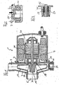
- a submersible motor pump 1 is shown schematically in longitudinal section in a working or operating position.
- a housing 3 is connected to a front side (left sides in Fig. 1) with a suction nozzle 5.
- the suction nozzle 5 is a part of a suction housing 7, on which a pumping neck 9 and an outlet 11 are formed.
- an impeller 13 is disposed in operative connection with the suction nozzle 5 and the pump nozzle 9, which is mounted on a shaft and in particular on a ceramic shaft 15.
- the ceramic shaft 15 has a shaft axis X, which extends in the illustrated working position in a substantially horizontal direction in a split tube 17, which is arranged in the housing 3.
- the ceramic shaft 15 is mounted at the connection point between the suction housing 7 and the can 17 in a ceramic bearing 19, which in turn is mounted in an elastic bushing 20. Between the ceramic bearing 19 and a seated on the ceramic shaft 15 in the gap tube 17 rotor 21, a water displacement body 23 is formed concentrically on the ceramic shaft 15, which fills a constructive space.
- the water displacement body 23 has the same radial extent from the shaft axis X as the rotor 21, so that an approximately uniform air gap 24 between an inner wall of the can 17 and the rotor 21 and the water displacement body 23 is formed, for example, a width of 0.2 mm can have.
- the outlet port 11 is located at the lowest point of the water or another liquid medium receiving portion of the submersible pump 1 and is separated with an elastic membrane 25 with respect to this region in the vertical direction.
- Fig. 2 is shown on the left half, as the elastic membrane 25 is undeformed under normal pressure conditions of water or other liquid medium. On the right half is shown how the elastic membrane 25 is deformed under ice pressure in frost.
- the impeller 13 is also fixed elastically to the ceramic shaft 15.
- an elastic impeller attachment 27 is shown, which holds the impeller on the ceramic shaft 15.
- the elastic impeller mounting 27 is in the present embodiment, an elastomer which is formed between a receiving sleeve 29 of the impeller 13 and the ceramic shaft 15 as an inner sleeve 31 and extending over a distance of the ceramic shaft 15 in the direction of the shaft axis X.
- each of the frost-protecting features of elastic bushing 19, water displacement body 23, elastic diaphragm 25 and elastic wheel mounting 27 per se improves the frost protection for a submersible pump 1.
- the frost protection is further optimized. In other embodiments, therefore, only a few of the aforementioned frost-protecting features or any combination thereof may be used in a submersible pump 1.
- elastic materials used for the features mentioned in the previous paragraph depends on the expected negative temperatures.
- elastomeric materials can be used, which are dimensionally stable and waterproof and not lose their elastic property even at minus temperatures.
- Such elastic materials are known in the art and include, for example, elastomeric materials such as natural or synthetic rubbers and rubber compounds.
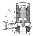
- a submersible motor pump 10 according to a second embodiment is shown schematically in longitudinal section in a working or operating position.
- a housing 30 is connected to a front side (left side in Fig. 4) with a suction nozzle 50.
- the suction nozzle 50 is part of a suction housing 70, on which a pumping neck 90 is formed.
- an impeller 130 is disposed in operative connection with the suction port 50 and the pump nozzle 90, which is mounted on a shaft and in particular on an oxide ceramic shaft 150.
- the oxide ceramic shaft 150 has a shaft axis X which, in the illustrated working position, extends in a substantially horizontal direction into a split tube 170 disposed in the housing 30.
- the impeller 130 may be attached to the oxide ceramic shaft 150 as well, as shown in Fig. 3 for the first embodiment
- the suction housing 70 is preceded by an annular space 190 in the direction of the suction nozzle 150.
- the suction nozzle 150 is screwed onto the suction housing 70 with the annular space 190 in the second embodiment.
- Other connections are also conceivable.
- a water displacement body 210 is arranged, the z. B. is a closed cell foam or a similar material, which is known from the prior art. It is conceivable z. As well as an air-filled membrane, similar to an expansion vessel in heaters.
- the annulus 190 is connected to the interior of the suction housing 70 through channels or slots 230. These slots 230 are distributed inside adjacent to the periphery of the suction housing 70. A water / ice pressure can escape through these slots 230 in the annular space 190.
- the submersible pump 10 may freeze in various spatial positions in this embodiment without being damaged by the water / ice pressure.
- a third embodiment of a submersible pump 10 according to the invention is shown schematically.
- the submersible pump 1 is identical to the submersible pump 10 of the second embodiment except for the antifreeze device, so that a further general description is omitted.
- the same components retain the reference numerals of the first and second embodiments.
- the frost protection device in this third embodiment also includes an annular space 1900. However, this is disposed between the suction housing 70 and the can 170.
- the annular space 1900 is the water displacement body 210, which may be designed as well as in the second embodiment.
- the annular space 1900 is via channels or slots 2300 on the one hand with the interior the Spaltrobres 170 and on the other hand connected to the interior of the suction housing 70.
- the slots 2300 are also arranged inside adjacent to the circumference of the suction housing 70 and the split tube 170. In this way, the water / ice pressure can escape both from the can 170 and from the suction housing and the submersible pump can freeze in various spatial positions without suffering frost damage.
- the third embodiment is suitable for so-called Nrustauerrmotoren in which the can 170 is filled with water.
Landscapes
- Engineering & Computer Science (AREA)
- Mechanical Engineering (AREA)
- General Engineering & Computer Science (AREA)
- Physics & Mathematics (AREA)
- Thermal Sciences (AREA)
- Structures Of Non-Positive Displacement Pumps (AREA)
Description
- Die vorliegende Erfindung betrifft eine Tauchmotorpumpe mit einem Gehäuse, mit einem an dem Gehäuse angebrachten Saugstutzen, mit einem in dem Saugstutzen angeordneten Laufrad zur Erzeugung einer Saugströmung und zum Transportieren eines Fluids zu einem Ausgabeanschluss hin, wobei das Laufrad auf einer Welle gelagert ist, die mit einem Motor verbunden ist, und mit einem Spaltrohr, in das sich die Welle hinein erstreckt.
- Solche Tauchmoterpumpen sind aus dem allgemeinen Stand der Technik bekannt, z.B. aus JP 11153098 A. Änliche Pumpe sind auch aus US 3045607 A, US 2002/076337 A, JP 11294366 A, JP 59018297 A, JP 58210396 A oder US 3313241 A bekannt. Wenn diese in einem Teich oder einem flüssigen Medium in nicht frostgeschützten Verhältnissen angeordnet werden, müssen sie in der Winterzeit von ihrem Standort genommen und frostsicher aufbewahrt werden. In einer Tauchpumpe ist in der Regel ein Laufrad über eine Keramikwelle mit einem Motor verbunden, der das Laufrad während des Pumpbetriebes antreibt.
- Es ist bekannt, dass Wellen aus Keramik gegenüber auf sie wirkenden Drucken empfindlich sind und leicht brechen können. Dennoch werden Keramikwellen in bekannten Tauchpumpen wegen zahlreicher anderer günstiger Eigenschaften bevorzugt.
- Im Winter friert das nicht frostsichere flüssige Medium von einer Oberfläche ausgehend nach unten durch. Wenn z.B. eine Tauchmotorpumpe in einem Gartenteich überwintert, kann diese in einer Frostperiode einfrieren. In einer solchen Tauchmotorpumpe befindet sich Teichwasser, das nach dem letzten Pumpbetrieb im Gehäuse verblieben ist oder nachträglich in die Gehäuseräume eingedrungen ist. Dieses Wasser friert von oben nach unten langsam durch und übt auf die in der Regel horizontal liegende Welle einen Druck aus. Wenn sich die Eisbildung im Gehäuse nach unten fortsetzt auch das Wasser unterhalb des seitlich und konzentrisch zur Welle angeordneten Saugstutzens ausdehnt, beginnt die eigentliche Frost-Bruchgefahr für die Welle und insbesondere für die Welle aus Keramik.
- Die Aufgabe der vorliegenden Erfindung ist daher, eine Tauchmotorpumpe zu schaffen, die auch in Frostzeiten in einem flüssigen und zufrierenden Medium verbleiben kann, ohne Schaden zu nehmen.
- Die Aufgabe wird erfindungsgemäß dadurch gelöst, dass in dem Gehäuse eine Frostschutzeinrichtung für die Welle angeordnet ist.
- Die Frostschutzeinrichtung schützt die Welle weitestgehend vor Frostschäden und insbesondere gegen einen frostbedingten Bruch.
- Ein weiterer Vorteil der vorliegenden Erfindung besteht darin, dass die Frostschutzeinrichtung beim Eintritt in das Spaltrohr in einer elastischen Buchse gelagert ist. Dadurch können Drucke quer zu einer Wellenachse X aufgefangen werden.
- Ein weiterer Vorteil besteht auch darin, dass die Frostschutzeinrichtung einen Wasserverdrängungskörper umfasst, der konzentrisch zur Welle oder Wellenachse X in Freiräumen angeordnet ist. Insbesondere gibt es in Abhängigkeit von der Wellenlänge einen großen Freiraum im Spaltrohr zwischen der elastischen Buchse und einem einen Rotor bildenden Teil des Motors. Der Wasserverdrängungskörper nimmt einen Raum ein, in welchem sich sonst das flüssige Medium und insbesondere das frierfäwge Teichwasser ansammeln würde und einen Druck auf die Welle ausüben würde. Der Wasserverdrängungskörper hält also das Wasser von der Welle fern.
- Ein weiterer Vorteil besteht darin, dass das Laufrad an der Welle elastisch befestigt ist. Eine solche elastische Befestigung erfolgt z.B. mit einem Elastomer.
- Noch einer weiterer Vorteil besteht darin, dass die tiefste Stelle eines Wasser aufnehmenden Bereich, in der Regel eine verschlossene Ablauföffnung unterhalb des Laufrades, mit einer elastischen Membrane verschlossen ist, die sich bei Frost ausdehnen kann, um einen Eisdruck von der Welle zu nehmen.
- Eine Ausführungsformen der vorliegenden Erfindung werden im Folgenden anhand der Zeichnungen näher beschrieben. Es zeigen:
- Fig. 1
- eine schematische Ansicht im Längsschnitt durch eine Tauchmotorpumpe mit einer Frostschutzeinrichtung gemäß einer ersten Ausführungsform der vorliegenden Erfindung;
- Fig. 2
- eine schematische Detailansicht aus Fig. 1, welche eine elastische Membrane im ausgedehnten Zustand in der rechten Hälfte und im nicht ausgedehnten Zustand in der linken Hälfte zeigt;
- Fig. 3
- eine schematische Detailansicht aus Fig. 1, welche eine elastische Laufradbefestigung zeigt;
- Fig. 4
- eine schematische Ansicht im Längsschnitt durch eine weitere Tauchmotorpumpe mit einer Frostschutzeinrichtung gemäß einer zweiten Ausführungsform der vorliegenden Erfindung ;
- Fig. 5
- eine schematische Ansicht im Längsschnitt durch eine weitere Tauchmotorpumpe mit einer Frostschutzeinrichtung gemäß einer dritten Ausführungsform der vorliegenden Erfindung ;
- In Fig. 1 ist schematisch eine Tauchmotorpumpe 1 im Längsschnitt in einer Arbeits- oder Betriebsposition dargestellt. Ein Gehäuse 3 ist an einer Stirnseite (linke Seiten in Fig. 1) mit einem Saugstutzen 5 verbunden. Der Saugstutzen 5 ist ein Teil eines Sauggehäuses 7, an dem auch ein Pumpstutzen 9 und ein Auslassstutzen 11 ausgebildet sind. In dem Sauggehäuse 7 ist in Wirkverbindung mit dem Saugstutzen 5 und dem Pumpstutzen 9 ein Laufrad 13 angeordnet, das auf einer Welle und insbesondere auf einer Keramikwelle 15 befestigt ist. Die Keramikwelle 15 hat eine Wellenachse X, die sich in der dargestellten Arbeitsposition in einer im wesentlichen horizontalen Richtung in ein Spaltrohr 17 erstreckt, das im Gehäuse 3 angeordnet ist. Die Keramikwelle 15 ist an der Verbindungsstelle zwischen Sauggehäuse 7 und Spaltrohr 17 in einem Keramiklager 19 gelagert, das wiederum in einer elastischen Buchse 20 gelagert ist. Zwischen dem Keramiklager 19 und einem auf der Keramikwelle 15 im Spaltrohr 17 sitzenden Rotor 21 ist ein Wasserverdrängungskörper 23 konzentrisch an der Keramikwelle 15 ausgebildet, der einen konstruktiven Freiraum füllt. Vorzugsweise hat der Wasserverdrängungskörper 23 die gleiche radiale Erstreckung von der Wellenachse X wie auch der Rotor 21, so dass ein in etwa gleichförmiger Luftspalt 24 zwischen einer Innenwand des Spaltrohres 17 und dem Rotor 21 bzw. dem Wasserverdrängungskörper 23 gebildet wird, der beispielsweise eine Breite von 0,2 mm haben kann.
- Der Auslassstutzen 11 befindet sich an der tiefsten Stelle des Wasser oder ein anderes flüsiges Medium aufnehmenden Bereichs der Tauchmotorpumpe 1 und ist mit einer elastischen Membrane 25 gegenüber diesem Bereich in vertikaler Richtung abgetrennt. In Fig. 2 ist auf der linken Hälfte dargestellt, wie die elastische Membrane 25 unter normalen Druckverhältnissen des Wassers oder sonstigen flüssigen Mediums unverformt ist. Auf der rechten Hälfte ist dargestellt, wie die elastische Membrane 25 unter Eisdruck bei Frost verformt wird.
- Das-Laufrad 13 ist an der Keramikwelle 15 auch elastisch befestigt. In Fig. 3 ist eine elastische Laufradbefestigung 27 dargestellt, welche das Laufrad an der Keramikwelle 15 hält. Die elastische Laufradbefestigung 27 ist in der vorliegenden Ausführungsform ein Elastomer, das zwischen einer Aufnahmehülse 29 des Laufrades 13 und der Keramikwelle 15 als Innenhülse 31 ausgebildet ist und sich über eine Strecke der Keramikwelle 15 in Richtung der Wellenachse X erstreckt.
- Jedes der vor Frost schützenden Merkmale von elastischer Buchse 19, Wasserverdrängungskörper 23, elastische Membrane 25 und elastische Laufradbefestigung 27 für sich verbessert den Frostschutz für eine Tauchmotorpumpe 1. Durch die Zusammenfügung der vorgenannten Einzelmerkmale wird der Frostschutz weiter optimiert. In anderen Ausführungsformen können daher auch nur einzelne der vorgenannten vor Frost schützenden Merkmale oder beliebige Kombinationen derselben in einer Tauchmotorpumpe 1 eingesetzt werden.
- Die Wahl der für die im vorher gehenden Absatz genannten Merkmale verwendeten elastischen Materialien ist abhängig von den zu erwartenden Minustemperaturen. So können alle im Stand der Technik bekannten elastomeren Materialien verwendet werden, die formstabil und wasserfest sind und auch bei Minustemperaturen ihre elastische Eigenschaft nicht verlieren. Solche elastischen Materialien sind aus dem Stand der Technik bekannt und umfassen nur beispielsweise elastomere Materialien, wie natürliche oder synthetische Gummis und Gummimischungen.
- In Fig. 4 ist schematisch eine Tauchmotorpumpe 10 gemäß einer zweiten Ausführungsform im Längsschnitt in einer Arbeits- oder Betriebsposition dargestellt. Ein Gehäuse 30 ist an einer Stirnseite (linke Seite in Fig. 4) mit einem Saugstutzen 50 verbunden. Der Saugstutzen 50 ist ein Teil eines Sauggehäuses 70, an dem auch ein Pumpstutzen 90 ausgebildet ist. In dem Sauggehäuse 70 ist in Wirkverbindung mit dem Saugstutzen 50 und dem Pumpstutzen 90 ein Laufrad 130 angeordnet, das auf einer Welle und insbesondere auf einer Oxidkeramikwelle 150 befestigt ist. Die Oxidkeramikwelle 150 hat eine Wellenachse X, die sich in der dargestellten Arbeitsposition in einer im wesentlichen horizontalen Richtung in ein Spaltrohr 170 erstreckt, das im Gehäuse 30 angeordnet ist.
- Das Laufrad 130 kann an der Oxidkeramikwelle 150 ebenso befestigt sein, wie dies in Fig. 3 für die erste Ausführungsform dargestellt ist
- In der zweiten Ausführungsform in Fig. 4 ist dem Sauggehäuse 70 ein Ringraum 190 in Richtung des Saugstutzens 150 vorgelagert. Der Saugstutzen 150 ist in der zweiten Ausführungsform mit dem Ringraum 190 auf das Sauggehäuse 70 aufgeschraubt. Andere Verbindungen sind aber auch denkbar. In dem Ringraum 190 ist ein Wasserverdrängungskörper 210 angeordnet, der z. B. ein Schaum mit geschlossenen Zellen oder ein ähnliches Material ist, das aus dem Stand der Technik bekannt ist. Vorstellbar ist z. B. auch eine luftgefüllte Membrane, ähnlich einem Ausdehnungsgefäß bei Heizungen.
- Der Ringraum 190 ist mit dem Inneren des Sauggehäuses 70 durch Kanäle oder Schlitze 230 verbunden. Diese Schlitze 230 sind innen angrenzend am Umfang des Sauggehäuses 70 verteilt. Ein Wasser-/Eisdruck kann durch diese Schlitze 230 in den Ringraum 190 ausweichen. Die Tauchpumpe 10 kann in dieser Ausführungsform in verschiedenen räumlichen Lagen einfrieren, ohne durch den Wasser-/Eisdruck beschädigt zu werden.
- In Fig. 5 ist schematisch eine dritte Ausführungsform einer erfindungsgemäßen Tauchpumpe 10 dargestellt. Die Tauchpumpe 1 ist mit Ausnahme der Frostschutzeinrichtung identisch mit der Tauchpumpe 10 der zweiten Ausführungsform, so daß auf eine weitere allgemeine Beschreibung verzichtet wird. Gleiche Bauteile behalten die Bezugszeichen der ersten und zweiten Ausführungsform. Die Frostschutzeinrichtung umfaßt in dieser dritten Ausführungsform auch einen Ringraum 1900. Dieser ist aber zwischen dem Sauggehäuse 70 und dem Spaltrohr 170 angeordnet In dem Ringraum 1900 befindet sich der Wasserverdrängungskörper 210, der ebenso beschaffen sein kann, wie in der zweiten Ausführungsform. Der Ringraum 1900 ist über Kanäle oder Schlitze 2300 einerseits mit dem Inneren des Spaltrobres 170 und andererseits mit dem Inneren des Sauggehäuses 70 verbunden. Die Schlitze 2300 sind auch hier innen angrenzend an den Umfang des Sauggehäuses 70 bzw. des Spaltrohrs 170 angeordnet. Auf diese Weise kann der Wasser-/ Eisdruck sowohl aus dem Spaltrohr 170 als auch aus dem Sauggehäuse entweichen und die Tauchpumpe kann in verschiedenen Raumlagen einfrieren, ohne einen Frostschaden zu erleiden.
- Die dritte Ausführungsform ist geeignet für sogenannte Naßläufermotoren, bei denen das Spaltrohr 170 mit Wasser gefüllt ist.
Claims (5)
- Tauchmotorpumpe (1) mit einem Gehäuse (3), mit einem an dem Gehäuse angebrachten Saugstutzen (5), mit einem in dem Saugstutzen angeordneten Laufrad (13) zur Erzeugung einer Saugströmung und zum Transportieren eines Fluids zu einem Ausgabeanschluss hin, wobei, das Laufrad auf einer Welle (15) gelagert ist, und mit einem Spaltrohr (17), in das sich die Welle hinein erstreckt,
dadurch gekennzeichnet,
dass in dem Gehäuse (3) eine Frostschutzeinrichtung (19, 23, 25, 27) für die Welle (15) angeordnet ist. - Tauchmotorpumpe nach Anspruch 1,
dadurch gekennzeichnet,
dass die Frostschutzeinrichtung (19, 23, 25, 27) eine elastische Buchse (20) aufweist, in der ein Lager (19) der Welle (15) am Eintritt in das Spaltrohr (17) gelagert ist und in einem sich konzentrisch um die Welle (15) erstreckenden Freiraum ein Wasserverdrängungskörper (23) angeordnet ist. - Tauchmotorpumpe nach Anspruch 1 oder 2,
dadurch gekennzeichnet,
dass die Frostschutzeinrichtung (19, 23, 25, 27) eine elastische Laufradbefestigung (27) aufweist. - Tauchmotorpumpe nach einem der Ansprüche 1 bis 3,
dadurch gekennzeichnet,
dass an einer in Betriebsposition tiefsten Stelle (11) eine elastische Membrane (25) angeordnet ist, die sich bei Eisdruck ausdehnen kann und dadurch den Eisdruck auf die Welle (15) vermindert. - Tauchmotorpumpe nach einem der vorstehenden Ansprüche,
dadurch gekennzeichnet,
dass die Welle (15) eine Keramikwelle ist.
Applications Claiming Priority (5)
| Application Number | Priority Date | Filing Date | Title |
|---|---|---|---|
| DE10240380 | 2002-08-31 | ||
| DE10240380 | 2002-08-31 | ||
| DE10331602 | 2003-07-12 | ||
| DE10331602A DE10331602B4 (de) | 2002-08-31 | 2003-07-12 | Tauchmotorpumpe mit Frostschutzeinrichtung |
| PCT/DE2003/002824 WO2004020835A1 (de) | 2002-08-31 | 2003-08-23 | Tauchmotorpumpe mit frostschutzeinrichtung |
Publications (2)
| Publication Number | Publication Date |
|---|---|
| EP1554497A1 EP1554497A1 (de) | 2005-07-20 |
| EP1554497B1 true EP1554497B1 (de) | 2006-04-12 |
Family
ID=31979465
Family Applications (1)
| Application Number | Title | Priority Date | Filing Date |
|---|---|---|---|
| EP03790739A Expired - Lifetime EP1554497B1 (de) | 2002-08-31 | 2003-08-23 | Tauchmotorpumpe mit frostschutzeinrichtung |
Country Status (7)
| Country | Link |
|---|---|
| US (1) | US20050254974A1 (de) |
| EP (1) | EP1554497B1 (de) |
| AT (1) | ATE323230T1 (de) |
| AU (1) | AU2003263144A1 (de) |
| CA (1) | CA2497056A1 (de) |
| DE (1) | DE50302976D1 (de) |
| WO (1) | WO2004020835A1 (de) |
Cited By (2)
| Publication number | Priority date | Publication date | Assignee | Title |
|---|---|---|---|---|
| WO2012025156A1 (de) | 2010-08-27 | 2012-03-01 | Gardena Manufacturing Gmbh | Gartenpumpe |
| CN104314879A (zh) * | 2014-11-07 | 2015-01-28 | 珠海格力电器股份有限公司 | 一种防冻裂水泵及空气能热水器 |
Families Citing this family (10)
| Publication number | Priority date | Publication date | Assignee | Title |
|---|---|---|---|---|
| EP2191104B1 (de) * | 2007-08-30 | 2019-12-04 | Micropump. Inc. | Pumpen und pumpenköpfe mit innendruckabsorptionsglied |
| BRPI0802897A2 (pt) * | 2008-08-19 | 2011-04-26 | Higra Ind Ltda | bombas modulares |
| US20110097219A1 (en) * | 2009-10-25 | 2011-04-28 | Kuo-Tung Hsu | Ice water pump |
| EP2546525B1 (de) * | 2011-07-13 | 2017-03-29 | Oase GmbH | Kreiselpumpe mit Spiralgehäuse |
| US9476424B2 (en) * | 2012-11-06 | 2016-10-25 | Nidec Motor Corporation | Appliance pump with angled flow path and axial flow impeller |
| CN105736399B (zh) * | 2016-03-09 | 2018-05-22 | 河北省机械科学研究设计院 | 一种双冷高效矿用隔爆型潜水电泵 |
| JP2018178742A (ja) * | 2017-04-04 | 2018-11-15 | 株式会社荏原製作所 | ポンプユニット |
| DE102018217179B4 (de) * | 2018-10-08 | 2023-06-29 | Vitesco Technologies GmbH | Fluidpumpe, Wasserfördereinheit, Wassereinspritzsystem, Verbrennungsmotor und Fahrzeug |
| DE102018217176B4 (de) * | 2018-10-08 | 2020-06-10 | Continental Automotive Gmbh | Fluidpumpe, Wasserfördereinheit, Wassereinspritzsystem, Verbrennungsmotor und Fahrzeug |
| DE202019101723U1 (de) | 2019-03-26 | 2020-06-29 | Meßner GmbH & Co. KG | Teichpumpe |
Family Cites Families (22)
| Publication number | Priority date | Publication date | Assignee | Title |
|---|---|---|---|---|
| US3045607A (en) * | 1960-04-11 | 1962-07-24 | Lindner Jacob | Well pumping system |
| US3046607A (en) * | 1961-07-17 | 1962-07-31 | Selas Corp Of America | Method of forming fused particles |
| US3313241A (en) * | 1965-09-23 | 1967-04-11 | Newman Jc | Over-the-top delivery for pumps having anti-freeze properties |
| US3402670A (en) * | 1966-06-01 | 1968-09-24 | Borg Warner | Rubber bearing for multistage pump |
| US3759290A (en) * | 1972-02-28 | 1973-09-18 | Trico Products Corp | Windshield washer system having submerged air driven pump |
| US3808830A (en) * | 1973-04-16 | 1974-05-07 | Gen Motors Corp | Thermally actuated suction throttling valve |
| JPS58210396A (ja) * | 1982-05-31 | 1983-12-07 | Mitsubishi Electric Corp | 自吸式電動ポンプ |
| JPS5918297A (ja) * | 1982-07-20 | 1984-01-30 | Mitsubishi Electric Corp | うず巻ポンプ |
| JPS6352992U (de) * | 1986-09-25 | 1988-04-09 | ||
| US4741715A (en) * | 1986-12-30 | 1988-05-03 | Brunswick Corporation | Pressure actuated drain valve for marine drive |
| US4872808A (en) * | 1987-06-22 | 1989-10-10 | Oil Dynamics, Inc. | Centrifugal pump modular bearing support for pumping fluids containing abrasive particles |
| DE3834667A1 (de) * | 1988-10-12 | 1990-04-19 | Klein Schanzlin & Becker Ag | Filtereinrichtung fuer einen spaltrohrmotor |
| US5297940A (en) * | 1992-12-28 | 1994-03-29 | Ingersoll-Dresser Pump Company | Sealless pump corrosion detector |
| US5372730A (en) * | 1993-08-17 | 1994-12-13 | A. W. Chesterton Company | Filtering system for pump shaft seals |
| US6558139B2 (en) * | 1995-12-04 | 2003-05-06 | Chemical Seal & Packing, Inc. | Bearings with hardened rolling elements and polymeric cages for use submerged in very low temperature fluids |
| DE19702723A1 (de) * | 1997-01-27 | 1998-08-06 | Grundfos As | Naßlaufender Tauchmotor zum Antreiben einer Kreiselpumpe |
| JPH11153098A (ja) * | 1997-09-19 | 1999-06-08 | Nikkiso Co Ltd | キャンドモータポンプ用凍結防止装置 |
| JPH11294366A (ja) * | 1998-04-16 | 1999-10-26 | Nikkiso Co Ltd | 凍結防止機構付き極低温用ポンプ |
| GB2353330B (en) * | 1999-08-04 | 2003-05-28 | Pet Mate Ltd | Pond pump |
| DE10024955A1 (de) * | 2000-05-22 | 2001-11-29 | Richter Chemie Tech Itt Gmbh | Kreiselpumpe mit Magnetkupplung |
| US6447269B1 (en) * | 2000-12-15 | 2002-09-10 | Sota Corporation | Potable water pump |
| US6479915B2 (en) * | 2001-03-08 | 2002-11-12 | Hung-Ming Hsueh | Structure of a submerged motor |
-
2003
- 2003-08-23 EP EP03790739A patent/EP1554497B1/de not_active Expired - Lifetime
- 2003-08-23 AT AT03790739T patent/ATE323230T1/de not_active IP Right Cessation
- 2003-08-23 AU AU2003263144A patent/AU2003263144A1/en not_active Abandoned
- 2003-08-23 US US10/526,038 patent/US20050254974A1/en not_active Abandoned
- 2003-08-23 CA CA002497056A patent/CA2497056A1/en not_active Abandoned
- 2003-08-23 DE DE50302976T patent/DE50302976D1/de not_active Expired - Lifetime
- 2003-08-23 WO PCT/DE2003/002824 patent/WO2004020835A1/de not_active Ceased
Cited By (2)
| Publication number | Priority date | Publication date | Assignee | Title |
|---|---|---|---|---|
| WO2012025156A1 (de) | 2010-08-27 | 2012-03-01 | Gardena Manufacturing Gmbh | Gartenpumpe |
| CN104314879A (zh) * | 2014-11-07 | 2015-01-28 | 珠海格力电器股份有限公司 | 一种防冻裂水泵及空气能热水器 |
Also Published As
| Publication number | Publication date |
|---|---|
| EP1554497A1 (de) | 2005-07-20 |
| ATE323230T1 (de) | 2006-04-15 |
| WO2004020835A1 (de) | 2004-03-11 |
| US20050254974A1 (en) | 2005-11-17 |
| CA2497056A1 (en) | 2004-03-11 |
| DE50302976D1 (de) | 2006-05-24 |
| AU2003263144A1 (en) | 2004-03-19 |
Similar Documents
| Publication | Publication Date | Title |
|---|---|---|
| DE102012111150B4 (de) | Elektrische Wasserpumpe | |
| DE19781894B4 (de) | Selbstansaugende Kreiselpumpe | |
| EP1687201B1 (de) | Strahlantrieb | |
| EP1554497A1 (de) | Tauchmotorpumpe mit frostschutzeinrichtung | |
| WO2009015957A1 (de) | Flüssigkeitspumpe | |
| EP1760322B1 (de) | Pumpe für Teich-, Aquarien- oder dergleichen Anlagen | |
| DE69100438T2 (de) | Pumpe mit Kompressor zur Verwendung im Bohrloch. | |
| DE1503586A1 (de) | Fluessigkeitsringpumpe und Verfahren zum Abdichten von Fluessigkeitsringpumpen | |
| DE10331602B4 (de) | Tauchmotorpumpe mit Frostschutzeinrichtung | |
| EP2609334B1 (de) | Gartenpumpe | |
| EP0386315A1 (de) | Abdichtungsvorrichtung sowie damit versehene Pumpe | |
| DE19548471C1 (de) | Umwälzpumpenaggregat | |
| WO2009015956A1 (de) | Flüssigkeitspumpe | |
| EP2431648A1 (de) | Leitungselement | |
| DE102011112580A1 (de) | Selbstansaugende Pumpe mit Schneidwerk | |
| DE102006023379A1 (de) | Flüssigkeitspumpe | |
| DE102018217179B4 (de) | Fluidpumpe, Wasserfördereinheit, Wassereinspritzsystem, Verbrennungsmotor und Fahrzeug | |
| DE3400396A1 (de) | Verfahren zum betrieb einer visco-luefterkupplung und visco-luefterkupplung nach diesem verfahren | |
| DE4330648A1 (de) | Radialpumpe | |
| EP3864294B1 (de) | Fluidpumpe, wasserfördereinheit, wassereinspritzsystem, verbrennungsmotor und fahrzeug | |
| WO2020074288A1 (de) | Fluidpumpe, wasserfördereinheit, wassereinspritzsystem, verbrennungsmotor und fahrzeug | |
| DE102018217181B4 (de) | Verwendung einer elektrisch angetriebenen Strömungspumpenstufe, einer Wasserfördereinheit, eines Wassereinspritzsystems, eines Verbrennungsmotors sowie eines Fahrzeugs | |
| DE102023102155A1 (de) | Trockenlaufendes Pumpenmodul mit Leckagereservoir | |
| AT265331B (de) | Kühlvorrichtung | |
| EP0718530A1 (de) | Pumpenaggregat |
Legal Events
| Date | Code | Title | Description |
|---|---|---|---|
| PUAI | Public reference made under article 153(3) epc to a published international application that has entered the european phase |
Free format text: ORIGINAL CODE: 0009012 |
|
| 17P | Request for examination filed |
Effective date: 20050224 |
|
| AK | Designated contracting states |
Kind code of ref document: A1 Designated state(s): AT BE BG CH CY CZ DE DK EE ES FI FR GB GR HU IE IT LI LU MC NL PT RO SE SI SK TR |
|
| AX | Request for extension of the european patent |
Extension state: AL LT LV MK |
|
| GRAP | Despatch of communication of intention to grant a patent |
Free format text: ORIGINAL CODE: EPIDOSNIGR1 |
|
| DAX | Request for extension of the european patent (deleted) | ||
| GRAS | Grant fee paid |
Free format text: ORIGINAL CODE: EPIDOSNIGR3 |
|
| GRAA | (expected) grant |
Free format text: ORIGINAL CODE: 0009210 |
|
| AK | Designated contracting states |
Kind code of ref document: B1 Designated state(s): AT BE BG CH CY CZ DE DK EE ES FI FR GB GR HU IE IT LI LU MC NL PT RO SE SI SK TR |
|
| PG25 | Lapsed in a contracting state [announced via postgrant information from national office to epo] |
Ref country code: IE Free format text: LAPSE BECAUSE OF FAILURE TO SUBMIT A TRANSLATION OF THE DESCRIPTION OR TO PAY THE FEE WITHIN THE PRESCRIBED TIME-LIMIT Effective date: 20060412 Ref country code: IT Free format text: LAPSE BECAUSE OF FAILURE TO SUBMIT A TRANSLATION OF THE DESCRIPTION OR TO PAY THE FEE WITHIN THE PRESCRIBED TIME-LIMIT;WARNING: LAPSES OF ITALIAN PATENTS WITH EFFECTIVE DATE BEFORE 2007 MAY HAVE OCCURRED AT ANY TIME BEFORE 2007. THE CORRECT EFFECTIVE DATE MAY BE DIFFERENT FROM THE ONE RECORDED. Effective date: 20060412 Ref country code: NL Free format text: LAPSE BECAUSE OF FAILURE TO SUBMIT A TRANSLATION OF THE DESCRIPTION OR TO PAY THE FEE WITHIN THE PRESCRIBED TIME-LIMIT Effective date: 20060412 Ref country code: SK Free format text: LAPSE BECAUSE OF FAILURE TO SUBMIT A TRANSLATION OF THE DESCRIPTION OR TO PAY THE FEE WITHIN THE PRESCRIBED TIME-LIMIT Effective date: 20060412 Ref country code: RO Free format text: LAPSE BECAUSE OF FAILURE TO SUBMIT A TRANSLATION OF THE DESCRIPTION OR TO PAY THE FEE WITHIN THE PRESCRIBED TIME-LIMIT Effective date: 20060412 Ref country code: CZ Free format text: LAPSE BECAUSE OF FAILURE TO SUBMIT A TRANSLATION OF THE DESCRIPTION OR TO PAY THE FEE WITHIN THE PRESCRIBED TIME-LIMIT Effective date: 20060412 Ref country code: SI Free format text: LAPSE BECAUSE OF FAILURE TO SUBMIT A TRANSLATION OF THE DESCRIPTION OR TO PAY THE FEE WITHIN THE PRESCRIBED TIME-LIMIT Effective date: 20060412 Ref country code: FI Free format text: LAPSE BECAUSE OF FAILURE TO SUBMIT A TRANSLATION OF THE DESCRIPTION OR TO PAY THE FEE WITHIN THE PRESCRIBED TIME-LIMIT Effective date: 20060412 |
|
| REG | Reference to a national code |
Ref country code: GB Ref legal event code: FG4D Free format text: NOT ENGLISH |
|
| REG | Reference to a national code |
Ref country code: CH Ref legal event code: EP |
|
| GBT | Gb: translation of ep patent filed (gb section 77(6)(a)/1977) |
Effective date: 20060412 |
|
| REF | Corresponds to: |
Ref document number: 50302976 Country of ref document: DE Date of ref document: 20060524 Kind code of ref document: P |
|
| REG | Reference to a national code |
Ref country code: IE Ref legal event code: FG4D Free format text: LANGUAGE OF EP DOCUMENT: GERMAN |
|
| PG25 | Lapsed in a contracting state [announced via postgrant information from national office to epo] |
Ref country code: DK Free format text: LAPSE BECAUSE OF FAILURE TO SUBMIT A TRANSLATION OF THE DESCRIPTION OR TO PAY THE FEE WITHIN THE PRESCRIBED TIME-LIMIT Effective date: 20060712 Ref country code: SE Free format text: LAPSE BECAUSE OF FAILURE TO SUBMIT A TRANSLATION OF THE DESCRIPTION OR TO PAY THE FEE WITHIN THE PRESCRIBED TIME-LIMIT Effective date: 20060712 |
|
| PG25 | Lapsed in a contracting state [announced via postgrant information from national office to epo] |
Ref country code: ES Free format text: LAPSE BECAUSE OF FAILURE TO SUBMIT A TRANSLATION OF THE DESCRIPTION OR TO PAY THE FEE WITHIN THE PRESCRIBED TIME-LIMIT Effective date: 20060723 |
|
| PG25 | Lapsed in a contracting state [announced via postgrant information from national office to epo] |
Ref country code: MC Free format text: LAPSE BECAUSE OF NON-PAYMENT OF DUE FEES Effective date: 20060831 Ref country code: BE Free format text: LAPSE BECAUSE OF NON-PAYMENT OF DUE FEES Effective date: 20060831 |
|
| ET | Fr: translation filed | ||
| PG25 | Lapsed in a contracting state [announced via postgrant information from national office to epo] |
Ref country code: PT Free format text: LAPSE BECAUSE OF FAILURE TO SUBMIT A TRANSLATION OF THE DESCRIPTION OR TO PAY THE FEE WITHIN THE PRESCRIBED TIME-LIMIT Effective date: 20060912 |
|
| NLV1 | Nl: lapsed or annulled due to failure to fulfill the requirements of art. 29p and 29m of the patents act | ||
| REG | Reference to a national code |
Ref country code: IE Ref legal event code: FD4D |
|
| PLBE | No opposition filed within time limit |
Free format text: ORIGINAL CODE: 0009261 |
|
| STAA | Information on the status of an ep patent application or granted ep patent |
Free format text: STATUS: NO OPPOSITION FILED WITHIN TIME LIMIT |
|
| 26N | No opposition filed |
Effective date: 20070115 |
|
| PG25 | Lapsed in a contracting state [announced via postgrant information from national office to epo] |
Ref country code: AT Free format text: LAPSE BECAUSE OF NON-PAYMENT OF DUE FEES Effective date: 20060823 |
|
| BERE | Be: lapsed |
Owner name: OASE G.M.B.H. Effective date: 20060831 |
|
| REG | Reference to a national code |
Ref country code: CH Ref legal event code: PL |
|
| PG25 | Lapsed in a contracting state [announced via postgrant information from national office to epo] |
Ref country code: LI Free format text: LAPSE BECAUSE OF NON-PAYMENT OF DUE FEES Effective date: 20070831 Ref country code: GR Free format text: LAPSE BECAUSE OF FAILURE TO SUBMIT A TRANSLATION OF THE DESCRIPTION OR TO PAY THE FEE WITHIN THE PRESCRIBED TIME-LIMIT Effective date: 20060713 Ref country code: CH Free format text: LAPSE BECAUSE OF NON-PAYMENT OF DUE FEES Effective date: 20070831 |
|
| PG25 | Lapsed in a contracting state [announced via postgrant information from national office to epo] |
Ref country code: EE Free format text: LAPSE BECAUSE OF FAILURE TO SUBMIT A TRANSLATION OF THE DESCRIPTION OR TO PAY THE FEE WITHIN THE PRESCRIBED TIME-LIMIT Effective date: 20060412 Ref country code: BG Free format text: LAPSE BECAUSE OF FAILURE TO SUBMIT A TRANSLATION OF THE DESCRIPTION OR TO PAY THE FEE WITHIN THE PRESCRIBED TIME-LIMIT Effective date: 20060712 |
|
| PG25 | Lapsed in a contracting state [announced via postgrant information from national office to epo] |
Ref country code: LU Free format text: LAPSE BECAUSE OF NON-PAYMENT OF DUE FEES Effective date: 20060823 Ref country code: TR Free format text: LAPSE BECAUSE OF FAILURE TO SUBMIT A TRANSLATION OF THE DESCRIPTION OR TO PAY THE FEE WITHIN THE PRESCRIBED TIME-LIMIT Effective date: 20060412 Ref country code: HU Free format text: LAPSE BECAUSE OF FAILURE TO SUBMIT A TRANSLATION OF THE DESCRIPTION OR TO PAY THE FEE WITHIN THE PRESCRIBED TIME-LIMIT Effective date: 20061013 |
|
| PG25 | Lapsed in a contracting state [announced via postgrant information from national office to epo] |
Ref country code: CY Free format text: LAPSE BECAUSE OF FAILURE TO SUBMIT A TRANSLATION OF THE DESCRIPTION OR TO PAY THE FEE WITHIN THE PRESCRIBED TIME-LIMIT Effective date: 20060412 |
|
| PGFP | Annual fee paid to national office [announced via postgrant information from national office to epo] |
Ref country code: GB Payment date: 20090223 Year of fee payment: 6 |
|
| PGFP | Annual fee paid to national office [announced via postgrant information from national office to epo] |
Ref country code: FR Payment date: 20090217 Year of fee payment: 6 |
|
| GBPC | Gb: european patent ceased through non-payment of renewal fee |
Effective date: 20090823 |
|
| REG | Reference to a national code |
Ref country code: FR Ref legal event code: ST Effective date: 20100430 |
|
| PG25 | Lapsed in a contracting state [announced via postgrant information from national office to epo] |
Ref country code: FR Free format text: LAPSE BECAUSE OF NON-PAYMENT OF DUE FEES Effective date: 20090831 |
|
| PG25 | Lapsed in a contracting state [announced via postgrant information from national office to epo] |
Ref country code: GB Free format text: LAPSE BECAUSE OF NON-PAYMENT OF DUE FEES Effective date: 20090823 |
|
| REG | Reference to a national code |
Ref country code: DE Ref legal event code: R082 Ref document number: 50302976 Country of ref document: DE Representative=s name: KAYSER & COBET PATENTANWAELTE PARTG, DE Ref country code: DE Ref legal event code: R082 Ref document number: 50302976 Country of ref document: DE Representative=s name: KAYSER & COBET, DE Ref country code: DE Ref legal event code: R082 Ref document number: 50302976 Country of ref document: DE Representative=s name: KAYSER & COBET PATENTANWAELTE PARTNERSCHAFT, DE |
|
| PGFP | Annual fee paid to national office [announced via postgrant information from national office to epo] |
Ref country code: DE Payment date: 20220905 Year of fee payment: 20 |
|
| REG | Reference to a national code |
Ref country code: DE Ref legal event code: R071 Ref document number: 50302976 Country of ref document: DE |