EP1553789A2 - Datenübertragung auf dem Meer - Google Patents
Datenübertragung auf dem Meer Download PDFInfo
- Publication number
- EP1553789A2 EP1553789A2 EP04106672A EP04106672A EP1553789A2 EP 1553789 A2 EP1553789 A2 EP 1553789A2 EP 04106672 A EP04106672 A EP 04106672A EP 04106672 A EP04106672 A EP 04106672A EP 1553789 A2 EP1553789 A2 EP 1553789A2
- Authority
- EP
- European Patent Office
- Prior art keywords
- ship
- base station
- data transmission
- network
- location information
- Prior art date
- Legal status (The legal status is an assumption and is not a legal conclusion. Google has not performed a legal analysis and makes no representation as to the accuracy of the status listed.)
- Granted
Links
- 230000005540 biological transmission Effects 0.000 title claims abstract description 42
- 238000000034 method Methods 0.000 claims description 12
- 230000010287 polarization Effects 0.000 claims description 6
- 230000011664 signaling Effects 0.000 claims description 4
- 238000005516 engineering process Methods 0.000 description 7
- 230000009977 dual effect Effects 0.000 description 3
- 238000004891 communication Methods 0.000 description 2
- 238000010276 construction Methods 0.000 description 2
- 230000006870 function Effects 0.000 description 2
- 238000010295 mobile communication Methods 0.000 description 2
- 230000004075 alteration Effects 0.000 description 1
- 230000003247 decreasing effect Effects 0.000 description 1
- 230000001419 dependent effect Effects 0.000 description 1
- 230000014509 gene expression Effects 0.000 description 1
- 238000005259 measurement Methods 0.000 description 1
- 238000003032 molecular docking Methods 0.000 description 1
- 230000001681 protective effect Effects 0.000 description 1
- 230000006641 stabilisation Effects 0.000 description 1
- 238000011105 stabilization Methods 0.000 description 1
- XLYOFNOQVPJJNP-UHFFFAOYSA-N water Substances O XLYOFNOQVPJJNP-UHFFFAOYSA-N 0.000 description 1
- 239000003643 water by type Substances 0.000 description 1
Images


Classifications
-
- H—ELECTRICITY
- H01—ELECTRIC ELEMENTS
- H01Q—ANTENNAS, i.e. RADIO AERIALS
- H01Q1/00—Details of, or arrangements associated with, antennas
- H01Q1/12—Supports; Mounting means
- H01Q1/22—Supports; Mounting means by structural association with other equipment or articles
- H01Q1/24—Supports; Mounting means by structural association with other equipment or articles with receiving set
- H01Q1/241—Supports; Mounting means by structural association with other equipment or articles with receiving set used in mobile communications, e.g. GSM
- H01Q1/246—Supports; Mounting means by structural association with other equipment or articles with receiving set used in mobile communications, e.g. GSM specially adapted for base stations
-
- H—ELECTRICITY
- H04—ELECTRIC COMMUNICATION TECHNIQUE
- H04W—WIRELESS COMMUNICATION NETWORKS
- H04W36/00—Hand-off or reselection arrangements
- H04W36/24—Reselection being triggered by specific parameters
- H04W36/32—Reselection being triggered by specific parameters by location or mobility data, e.g. speed data
-
- G—PHYSICS
- G01—MEASURING; TESTING
- G01S—RADIO DIRECTION-FINDING; RADIO NAVIGATION; DETERMINING DISTANCE OR VELOCITY BY USE OF RADIO WAVES; LOCATING OR PRESENCE-DETECTING BY USE OF THE REFLECTION OR RERADIATION OF RADIO WAVES; ANALOGOUS ARRANGEMENTS USING OTHER WAVES
- G01S5/00—Position-fixing by co-ordinating two or more direction or position line determinations; Position-fixing by co-ordinating two or more distance determinations
- G01S5/02—Position-fixing by co-ordinating two or more direction or position line determinations; Position-fixing by co-ordinating two or more distance determinations using radio waves
- G01S5/0284—Relative positioning
-
- H—ELECTRICITY
- H04—ELECTRIC COMMUNICATION TECHNIQUE
- H04B—TRANSMISSION
- H04B7/00—Radio transmission systems, i.e. using radiation field
- H04B7/14—Relay systems
- H04B7/15—Active relay systems
- H04B7/155—Ground-based stations
- H04B7/15528—Control of operation parameters of a relay station to exploit the physical medium
- H04B7/15535—Control of relay amplifier gain
-
- H—ELECTRICITY
- H04—ELECTRIC COMMUNICATION TECHNIQUE
- H04W—WIRELESS COMMUNICATION NETWORKS
- H04W16/00—Network planning, e.g. coverage or traffic planning tools; Network deployment, e.g. resource partitioning or cells structures
- H04W16/24—Cell structures
- H04W16/28—Cell structures using beam steering
-
- H—ELECTRICITY
- H04—ELECTRIC COMMUNICATION TECHNIQUE
- H04B—TRANSMISSION
- H04B7/00—Radio transmission systems, i.e. using radiation field
- H04B7/02—Diversity systems; Multi-antenna system, i.e. transmission or reception using multiple antennas
- H04B7/10—Polarisation diversity; Directional diversity
-
- H—ELECTRICITY
- H04—ELECTRIC COMMUNICATION TECHNIQUE
- H04B—TRANSMISSION
- H04B7/00—Radio transmission systems, i.e. using radiation field
- H04B7/14—Relay systems
- H04B7/15—Active relay systems
- H04B7/185—Space-based or airborne stations; Stations for satellite systems
- H04B7/18502—Airborne stations
- H04B7/18506—Communications with or from aircraft, i.e. aeronautical mobile service
- H04B7/18508—Communications with or from aircraft, i.e. aeronautical mobile service with satellite system used as relay, i.e. aeronautical mobile satellite service
-
- H—ELECTRICITY
- H04—ELECTRIC COMMUNICATION TECHNIQUE
- H04W—WIRELESS COMMUNICATION NETWORKS
- H04W64/00—Locating users or terminals or network equipment for network management purposes, e.g. mobility management
- H04W64/006—Locating users or terminals or network equipment for network management purposes, e.g. mobility management with additional information processing, e.g. for direction or speed determination
-
- H—ELECTRICITY
- H04—ELECTRIC COMMUNICATION TECHNIQUE
- H04W—WIRELESS COMMUNICATION NETWORKS
- H04W84/00—Network topologies
- H04W84/02—Hierarchically pre-organised networks, e.g. paging networks, cellular networks, WLAN [Wireless Local Area Network] or WLL [Wireless Local Loop]
- H04W84/04—Large scale networks; Deep hierarchical networks
Definitions
- the present invention relates to wireless data transmission and more particularly to transmission between a fixed network and a moving vessel such as a ship.
- Broadband systems use transmission channels that are capable of supporting data rates greater than primary rates.
- a broad frequency band allows a data transmission capacity of the order of 2 Mbit/s or more.
- the broadband technology enables its users to gain access to high-speed digital technologies such as integrated access to voice, high-speed data transmission, video conference and video-on-demand services.
- One of the problems associated with the above arrangement is the limited capacity of the satellite technology.
- TV companies may require high rental fees for utilizing their satellite capacity.
- the direction of the satellite antennas on the ship causes problems since the position of the ship changes constantly.
- the ship body may also generate reflections and shadow zones where the satellite signal cannot be reached.
- An object of the present solution is thus to provide a method and an apparatus for implementing the method so as to overcome the above problems.
- the objects of the application are achieved by a method, system and base station, which are characterized by what is stated in the independent claims. Embodiments of the solution are disclosed in the dependent claims.
- the solution of the present application is based on the idea of providing a ship on the sea an access to on-shore telecommunications network services by means of a microwave radio link.
- a wireless connection between the ship and the on-shore network is established using a microwave link between a telecommunications system of the ship and a base station of the on-shore network.
- the appropriate direction for the data transmission from the ship to the base station is calculated utilizing the momentary location of the ship and the location of the base station in question.
- the swaying angle of the ship is compensated by means of a gyroscope.
- the ship is provided with dual antennas such that at each time a first antenna is selected as an active antenna and a second as a standby antenna.
- the antenna receiving a stronger threshold signal from the base station is usually selected as the active antenna.
- the standby antenna begins to search for the next base station.
- a handover may be performed when the threshold signal of the new base station is stronger than that of the original base station.
- An advantage of the present solution is that it provides a feasible alternative for broadband data transmission between a ship and an on-shore network.
- a high data transmission rate can be maintained since a significant portion of the frequency bandwidth can be used for the actual data transmission, and only a minor part of the frequency bandwidth has to be reserved for signalling.
- the solution enables transmission of packet switched data as well as circuit switched data.
- UMTS Universal mobile telecommunications system
- the solution may be applied in any wireless communications system providing data transmission services.
- Such systems include, for instance, systems based on GSM (Global system for mobile communication) or corresponding systems, such as GSM2+ systems and the future 4 th generation systems.
- GSM Global system for mobile communication
- GSM2+ Global system for mobile communication
- GSM2+ Global system for mobile communication
- the specifications of the wireless communications systems advance rapidly. This may require additional changes to the solution. For this reason, the terminology and the expressions used should be interpreted in their broadest sense since they are meant to illustrate the solution and not to restrict it.
- the relevant inventive aspect is the functionality concerned, not the network element or equipment where it is executed.
- Microwave radio is a transmission technique that involves fixed, accurately directed radio links with operating frequencies of about 7 to 38 GHz.
- the microwave radio technique allows a data transmission capacity of 2 to 2 x 17 Mbit/s, depending on the available bandwidth.
- the link comprises a signalling channel and a data transmission channel.
- the applications are of the microwave radio are, for example, in radio links between a base station and a radio network controller, in docking of satellites, and in missile systems.
- a gyroscope device is based on an electrically rotated wheel at high speed in a low-friction bearing. When the device is moved in different directions the gyroscope will still point in the original direction. This is because any alteration of the inclination of the rotation axis is resisted by a turning movement (gyrostatic moment). This can be measured and the results can be used in ship stabilization, inertial measuring and navigation systems etc.
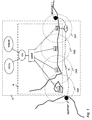
- the telecommunication system S comprises an on-shore telecommunications network N.
- the network N may be a mobile network comprising a core network CN, and at least one fixed base station BS1, BS2, BS3, BS4 for connecting the mobile terminals into the core network.
- the core network CN may further comprise network elements (not shown) such as a mobile switching centre (MSC), a serving GPRS support node (SGSN) and a gateway GPRS support node (GGSN).
- MSC mobile switching centre
- SGSN serving GPRS support node
- GGSN gateway GPRS support node
- the core network described herein is based on a 3G UMTS network.
- Other types of core networks, for example the GSM may comprise other network elements.
- the base stations BS1, BS2, BS3, BS4 are connected to the core network CN via a switch.
- the switch may comprise a radio network controller (RNC) or the like for controlling the radio resources of the network N.
- the base stations BS1, BS2, BS3, BS4 may be located on the shore and/or on an island or islet or the like.
- the coverage areas of the base stations BS1, BS2, BS3, BS4 are illustrated here by circles CA1, CA2, CA3, CA4 respectively. However, they could also of other shapes, such as ellipses or conical shapes.
- the core network CN is connected to an outside network, such as the Internet and/or the Publicly switched telephone network PSTN in order to provide the mobile subscribers access to these networks.
- the telecommunications system of the present solution further comprises an Intranet or an equivalent network (not shown) on the ship L. It may be implemented using WLAN (Wireless local area network) or Bluetooth technology, for example.
- FIG. 1 a situation is shown where the ship L is sailing on the sea and located on the coverage area CA1 of BS1.
- the ship L is moving towards the coverage area CA2 of BS2.
- the ship L and the base station are able to establish a wireless microwave radio link between each other, as illustrated by an arrow.
- the ship route R comprises a journey from seaport 1 to seaport 2.
- the water area in question does not necessarily have to be a sea; it may also be a lake or a river, for example.
- CN comprises a central computer unit for storing information of the route of the ship.
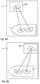
- stage 2-1 a situation is shown where a base station BS1 and a ship L, located on the coverage area of BS1, have established a wireless data connection with each other by means of a microwave radio link using antennas A1, A2, A3.
- antennas A1, A2, A3 there is one antenna A1 in the base station BS1 and two antennas A2, A3 on the ship L capable of receiving and transmitting broadband data using a microwave link.
- A2 and A3 are currently directed towards BS1 for transmitting/receiving data to/from BS1.
- a dual polarization microwave link is utilized such that the link between L and BS1 is implemented as two microwave beams (as indicated by arrows), which have equal frequency magnitudes but different polarizations, meaning that data may be transmitted using a vertically or a horizontally polarized microwave.
- the vertically polarized wave is used between A1 and A2, and the horizontally polarized wave is used between A1 and A3, or wise versa.
- One of the waves is selected as an active wave and the other as a standby wave. The signalling and data transmission occurs using the active wave.
- stage 2-2 as the ship moves, the direction of the antenna beams of A2 and A3 is updated and A2 and A3 are redirected towards the base station.
- the redirection of the antennas of the ship is based on the current location of the ship, compensating of the swaying of the ship, and the location of the base station BS1.
- the ship receives updated information of its own location from the GPS system or from the steering system of the ship. Information of the location of the base stations by the route of the ship is maintained on the ship.
- the turning of the antennas is carried out, for example, by means of an azimuth motor.
- the weather, waves etc. may cause vertical and/or horizontal swaying of the ship.
- the ship L is provided with sensors for measuring the swaying angle of the ship.
- the swaying of the ship is compensated by means of a gyroscope system.
- the gyroscope of the ship receives updated information of the swaying angle from the sensors and it adjusts the direction of the antennas A2, A3 so that the microwave connection between the ship and the base station can be maintained.
- Transmitting of automatic gain control (AGC) signals is a feature of the microwave radio, which allows the receiver of the signals to evaluate and follow the voltage level of the received signals.
- AGC automatic gain control
- the antennas of the ship are able to choose for the data transmission the base station, which has the highest voltage level of an AGC signal received in the antenna.
- the selecting of which is the active signal and which is the standby signal of the dual polarization link is based on the measurement of the AGC signal strength such that the received signal having the higher voltage level of the AGC signal is selected as the active one.
- stage 2-3 a situation is shown where the ship is about to leave the coverage area of BS1, and the voltage level of the AGC signals received by A2 from BS1 has decreased under a predetermined threshold value.
- A2 begins to search for the AGC signal of the next base station BS2, and thus, by means of the azimuth motor, A2 is turned towards BS2 (comprising an antenna A1').
- the redirection of A2 towards BS2 is based on the current location of the ship and the location information of BS2.
- the link between A1 and A3 is the active link.
- BS2 is already waiting for the approaching ship L and searching for the AGC signal of the ship L, based on the information of the route of the ship received from the central computer unit.
- stage 2-4 a situation is shown where A2 has received the AGC signal of the next base station BS2.
- A2 is directed towards BS2, but A3 is still directed towards BS1.
- the direction of A2 towards BS2 is based on the current location of the ship, compensating of the swaying of the ship, and the location of BS2. Transmission is possible between A3 and A1, and between A2 and A1'.
- the two links have different polarizations, and the link having the higher AGC signal strength received on the ship is selected as the active link.
- stage 2-5 a situation is shown where the ship L has moved further, and the voltage level of the AGC signal from BS1 received in A3 has declined under a predetermined value.
- Transmission between the ship L and BS1 is interrupted, and A3 is turning towards BS2.
- A3 is searching for the AGC signal of BS2.
- the redirection of A3 towards BS2 is based on the current location of the ship and the location of BS2.
- the link between A1' and A2 is the active link.
- BS1 may be getting ready for the next ship.
- stage 2-6 a situation is shown where transmission between the A2 and A1', and between A3 and A1' is possible.
- One of the links is the active link, based on the AGC signal strength.
- the direction of the antennas A2 and A3 is based on the current location of the ship, compensating of the swaying of the ship, and the location of the base station BS2.
- the transmission process continues in a manner described above with reference to Figures 2a) to 2f).
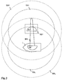
- Figure 3 illustrates the coverage area CA1 of the base station BA1 and the search area SAL of the antenna A2 of the ship L. For reasons of clarity only of the ship antennas is shown.
- TA1 the strength of the AGC signal of A1 is above the predetermined threshold value.
- TAL the strength of the AGC signal of A2 is above the predetermined threshold value.
- CA1, SAL, TA1 and TAL comprise a circle but they could as well be of some other form.
- the antenna A2 of the ship L comprises an adjustable parabolic antenna capable of transmitting a focused microwave beam ML inside the search area CAL circle. A2 can be redirected in vertical and/or horizontal direction as the ship moves.
- the redundancy antenna, A3 in Figures 2a) - 2f), of the ship may be used if there is an obstacle (such as another ship) between A1 and A2 and/or if the received AGC signal strength in A2 drops under a predetermined value.
- the antenna beam of A1 is not focused, and it is directed based on the GPS location of the ship.
- the antenna beam of the ship may be adjusted in horizontal direction.
- the ship and or the base station are provided with a subantenna for transmitting and/or receiving of AGC signals.
- the maximum distance, at which a ship is able to receive/transmit data according to the present solution depends, for example, on the capability of the antennas of the ship and of the base station. According to another embodiment, the maximum distance is preferably about 40 to 50 km.
- the solution of the present application enables data transmission to/from the ship even if the route of the ship comprises territorial waters of a foreign country. This may be implemented so that the nationality of the ship is declared as changed when the roaming begins, and the original nationality is returned when the roaming ends.
- the data transmission between the ship and the on-shore network is based on a contract between the respective shipping company and network operator.
- the system of the present application is utilized in some other vessel, such as a train or a bus.
- the base station of the present solution may be a conventional UMTS or GSM base station, provided with a computer unit and the antenna for performing functions of the present solution.
- the computer unit of the base station receives information of an approaching ship from a central computer in the CN.
- the base station may transmit the information of the actual location of the ship to the central computer unit so that the central computer may store the information and/or inform other base stations of the location of the ship.
- the base station searches for the AGC signal of the ship and may establish a microwave link with a ship antenna having the strongest AGC signal.
- Constructions of the system can be planned so that they tolerate different weather conditions, such as wind, snow, ice, and various operation temperatures, for example, temperatures from -33 to +40 °C.
- the system implementing the operation according to the present solution are configured to store the route of the ship and the location information of the base stations.
- the existing networks, network nodes and base stations comprise processors and memory, which can be used in the functions according to the solution. Changes needed to implement the present solution may be carried out by means of software routines that can be added or updated and/or routines contained in application specific integrated circuits (ASIC) and/or programmable circuits, such as an electrically programmable logic device EPLD or a field programmable gate array FPGA.
- ASIC application specific integrated circuits
- EPLD electrically programmable logic device
- FPGA field programmable gate array
Landscapes
- Engineering & Computer Science (AREA)
- Computer Networks & Wireless Communication (AREA)
- Signal Processing (AREA)
- Remote Sensing (AREA)
- General Physics & Mathematics (AREA)
- Radar, Positioning & Navigation (AREA)
- Physics & Mathematics (AREA)
- Mobile Radio Communication Systems (AREA)
- Radio Relay Systems (AREA)
- Position Fixing By Use Of Radio Waves (AREA)
- Arrangements For Transmission Of Measured Signals (AREA)
- Radar Systems Or Details Thereof (AREA)
- Measurement Of Velocity Or Position Using Acoustic Or Ultrasonic Waves (AREA)
Applications Claiming Priority (2)
| Application Number | Priority Date | Filing Date | Title |
|---|---|---|---|
| FI20031900A FI120570B (fi) | 2003-12-23 | 2003-12-23 | Datan lähettäminen merellä |
| FI20031900 | 2003-12-23 |
Publications (3)
| Publication Number | Publication Date |
|---|---|
| EP1553789A2 true EP1553789A2 (de) | 2005-07-13 |
| EP1553789A3 EP1553789A3 (de) | 2009-09-16 |
| EP1553789B1 EP1553789B1 (de) | 2017-05-03 |
Family
ID=29763588
Family Applications (1)
| Application Number | Title | Priority Date | Filing Date |
|---|---|---|---|
| EP04106672.1A Expired - Lifetime EP1553789B1 (de) | 2003-12-23 | 2004-12-17 | Datenübertragung auf dem meer |
Country Status (4)
| Country | Link |
|---|---|
| EP (1) | EP1553789B1 (de) |
| DK (1) | DK1553789T3 (de) |
| FI (1) | FI120570B (de) |
| NO (1) | NO337834B1 (de) |
Cited By (7)
| Publication number | Priority date | Publication date | Assignee | Title |
|---|---|---|---|---|
| GB2501809A (en) * | 2012-04-26 | 2013-11-06 | Korea Electronics Telecomm | Maritime wireless communication apparatus using vertically spaced antennas to provide frequency and space diversity gain |
| WO2016204333A1 (ko) * | 2015-06-15 | 2016-12-22 | (주)에이엠플러스 | 해상용 안테나 장치 및 이의 운용 방법 |
| WO2018188274A1 (zh) * | 2017-04-14 | 2018-10-18 | 京东方科技集团股份有限公司 | 移动设备以及移动设备定向天线调节方法 |
| WO2019129847A1 (en) * | 2017-12-28 | 2019-07-04 | Miwire Aps | Route-based directional antenna |
| WO2020162817A1 (en) * | 2019-02-06 | 2020-08-13 | Aecorlink Ab | An antenna terminal, a rotatable antenna platform and methods for maritime use |
| US20220070686A1 (en) * | 2020-08-28 | 2022-03-03 | GM Global Technology Operations LLC | Method and system for beamform management in vehicular communications |
| CN114745758A (zh) * | 2022-05-07 | 2022-07-12 | 广州海事科技有限公司 | 多基站融合通信方法、系统、计算机设备及存储介质 |
Citations (1)
| Publication number | Priority date | Publication date | Assignee | Title |
|---|---|---|---|---|
| WO1998016077A2 (en) | 1996-10-10 | 1998-04-16 | Teratech Corporation | Communication system using geographic position data |
Family Cites Families (5)
| Publication number | Priority date | Publication date | Assignee | Title |
|---|---|---|---|---|
| US6104933A (en) * | 1997-06-23 | 2000-08-15 | Telefonaktiebolaget Lm Ericsson | Method and apparatus for control of base stations in macro diversity radio systems |
| DE10004000A1 (de) * | 2000-01-29 | 2001-08-02 | Bosch Gmbh Robert | Mobiles Kommunikationssystem |
| US7181244B2 (en) * | 2000-11-16 | 2007-02-20 | Qualcomm, Incorporated | Method and apparatus for using position location to direct narrow beam antennas |
| GB2380355B (en) * | 2001-08-03 | 2003-08-06 | Hutchison Whampoa Entpr Ltd | Mobile telephone communications networks |
| EP1369954A3 (de) * | 2002-06-05 | 2004-10-20 | Fujitsu Limited | Adaptive Antenneneinheit für Mobilgerät |
-
2003
- 2003-12-23 FI FI20031900A patent/FI120570B/fi not_active IP Right Cessation
-
2004
- 2004-12-17 EP EP04106672.1A patent/EP1553789B1/de not_active Expired - Lifetime
- 2004-12-17 DK DK04106672.1T patent/DK1553789T3/en active
- 2004-12-22 NO NO20045597A patent/NO337834B1/no not_active IP Right Cessation
Patent Citations (1)
| Publication number | Priority date | Publication date | Assignee | Title |
|---|---|---|---|---|
| WO1998016077A2 (en) | 1996-10-10 | 1998-04-16 | Teratech Corporation | Communication system using geographic position data |
Cited By (11)
| Publication number | Priority date | Publication date | Assignee | Title |
|---|---|---|---|---|
| GB2501809A (en) * | 2012-04-26 | 2013-11-06 | Korea Electronics Telecomm | Maritime wireless communication apparatus using vertically spaced antennas to provide frequency and space diversity gain |
| GB2501809B (en) * | 2012-04-26 | 2014-10-15 | Korea Electronics Telecomm | Maritime wireless communication apparatus and method |
| WO2016204333A1 (ko) * | 2015-06-15 | 2016-12-22 | (주)에이엠플러스 | 해상용 안테나 장치 및 이의 운용 방법 |
| WO2018188274A1 (zh) * | 2017-04-14 | 2018-10-18 | 京东方科技集团股份有限公司 | 移动设备以及移动设备定向天线调节方法 |
| US10939351B2 (en) | 2017-04-14 | 2021-03-02 | Boe Technology Group Co., Ltd. | Mobile device and directional antenna adjustment method of mobile device |
| WO2019129847A1 (en) * | 2017-12-28 | 2019-07-04 | Miwire Aps | Route-based directional antenna |
| US11600899B2 (en) | 2017-12-28 | 2023-03-07 | Miwire Aps | Route-based directional antenna |
| WO2020162817A1 (en) * | 2019-02-06 | 2020-08-13 | Aecorlink Ab | An antenna terminal, a rotatable antenna platform and methods for maritime use |
| US20220070686A1 (en) * | 2020-08-28 | 2022-03-03 | GM Global Technology Operations LLC | Method and system for beamform management in vehicular communications |
| US11375386B2 (en) * | 2020-08-28 | 2022-06-28 | GM Global Technology Operations LLC | Method and system for beamform management in vehicular communications |
| CN114745758A (zh) * | 2022-05-07 | 2022-07-12 | 广州海事科技有限公司 | 多基站融合通信方法、系统、计算机设备及存储介质 |
Also Published As
| Publication number | Publication date |
|---|---|
| EP1553789A3 (de) | 2009-09-16 |
| NO20045597L (no) | 2005-06-24 |
| FI20031900L (fi) | 2005-06-24 |
| FI120570B (fi) | 2009-11-30 |
| FI20031900A0 (fi) | 2003-12-23 |
| EP1553789B1 (de) | 2017-05-03 |
| DK1553789T3 (en) | 2017-08-28 |
| NO337834B1 (no) | 2016-06-27 |
Similar Documents
| Publication | Publication Date | Title |
|---|---|---|
| US5559806A (en) | Transceiver having steerable antenna and associated method | |
| KR100951030B1 (ko) | 적응성 안테나를 사용하는 통신 핸드오프 방법 및 장치 | |
| CN1640162B (zh) | 为偏远服务地区使用移动台而设立的移动网络 | |
| US5161248A (en) | Method of predicting cell-to-cell hand-offs for a satellite cellular communications system | |
| US20170180035A1 (en) | Ground terminal and gateway beam pointing toward an unmanned aerial vehicle (uav) for network access | |
| EP1976152A1 (de) | Verfahren und System zur Bereitstellung einer Luft-Boden-Verbindung | |
| EP3646481B1 (de) | Kommunikation mit einem mobilen gerät | |
| US20090028573A1 (en) | Mobile communications via an optical signal during adverse atmospheric conditions | |
| JPH0787011A (ja) | 無線通信システム及び無線装置及びスイッチ | |
| US11600899B2 (en) | Route-based directional antenna | |
| US6941107B2 (en) | Stratospheric platform based surface vehicle tracking and mobile data network | |
| CN106954223A (zh) | 一种动中通端站系统及动中通端站系统的通信方法 | |
| EP3958477B1 (de) | Drahtlose kommunikation für fahrzeugbasierten knoten | |
| KR100885695B1 (ko) | 이동 통신 시스템 | |
| EP1553789B1 (de) | Datenübertragung auf dem meer | |
| CN100459753C (zh) | 用于移动平台的低高度、低成本、高增益天线和系统 | |
| WO2004025900A2 (en) | Mobile communication system using directional antennas | |
| US20240251322A1 (en) | Satellite Communication Handover Method, Control Apparatus, and Terminal Device | |
| JP2001517913A (ja) | 移動電話システムにおける移動ターミナルの地理的位置の決定 | |
| US20240365199A1 (en) | System and method for cell handover from non-terrestrial networks to terrestrial networks | |
| WO2020162817A1 (en) | An antenna terminal, a rotatable antenna platform and methods for maritime use | |
| KR100576666B1 (ko) | 위성 통신 방법, 그 방법에 이용하는 이동국 및게이트웨이국 | |
| US20230231619A1 (en) | Beam pointing fine tuning for vehicle-based antennas | |
| Chen et al. | Adaptive beamforming methods based on air-to-ground communication scenarios | |
| WO2010050631A1 (en) | Mobile communication repeating method in moving object and repeater thereof |
Legal Events
| Date | Code | Title | Description |
|---|---|---|---|
| PUAI | Public reference made under article 153(3) epc to a published international application that has entered the european phase |
Free format text: ORIGINAL CODE: 0009012 |
|
| AK | Designated contracting states |
Kind code of ref document: A2 Designated state(s): AT BE BG CH CY CZ DE DK EE ES FI FR GB GR HU IE IS IT LI LT LU MC NL PL PT RO SE SI SK TR |
|
| AX | Request for extension of the european patent |
Extension state: AL BA HR LV MK YU |
|
| PUAL | Search report despatched |
Free format text: ORIGINAL CODE: 0009013 |
|
| AK | Designated contracting states |
Kind code of ref document: A3 Designated state(s): AT BE BG CH CY CZ DE DK EE ES FI FR GB GR HU IE IS IT LI LT LU MC NL PL PT RO SE SI SK TR |
|
| AX | Request for extension of the european patent |
Extension state: AL BA HR LV MK YU |
|
| 17P | Request for examination filed |
Effective date: 20091118 |
|
| AKX | Designation fees paid |
Designated state(s): AT BE BG CH CY CZ DE DK EE ES FI FR GB GR HU IE IS IT LI LT LU MC NL PL PT RO SE SI SK TR |
|
| AXX | Extension fees paid |
Extension state: LV Payment date: 20091118 |
|
| 17Q | First examination report despatched |
Effective date: 20110819 |
|
| REG | Reference to a national code |
Ref country code: DE Ref legal event code: R079 Ref document number: 602004051183 Country of ref document: DE Free format text: PREVIOUS MAIN CLASS: H04Q0007200000 Ipc: H04B0007100000 |
|
| RIC1 | Information provided on ipc code assigned before grant |
Ipc: H04W 16/28 20090101ALI20160704BHEP Ipc: H04W 64/00 20090101ALI20160704BHEP Ipc: H01Q 1/24 20060101ALI20160704BHEP Ipc: H04W 84/04 20090101ALI20160704BHEP Ipc: G01S 5/02 20060101ALI20160704BHEP Ipc: H04B 7/185 20060101ALI20160704BHEP Ipc: H04B 7/10 20060101AFI20160704BHEP |
|
| GRAP | Despatch of communication of intention to grant a patent |
Free format text: ORIGINAL CODE: EPIDOSNIGR1 |
|
| INTG | Intention to grant announced |
Effective date: 20161115 |
|
| GRAS | Grant fee paid |
Free format text: ORIGINAL CODE: EPIDOSNIGR3 |
|
| GRAA | (expected) grant |
Free format text: ORIGINAL CODE: 0009210 |
|
| AK | Designated contracting states |
Kind code of ref document: B1 Designated state(s): AT BE BG CH CY CZ DE DK EE ES FI FR GB GR HU IE IS IT LI LT LU MC NL PL PT RO SE SI SK TR |
|
| AX | Request for extension of the european patent |
Extension state: LV |
|
| REG | Reference to a national code |
Ref country code: GB Ref legal event code: FG4D |
|
| REG | Reference to a national code |
Ref country code: DE Ref legal event code: R081 Ref document number: 602004051183 Country of ref document: DE Owner name: TELIA FINLAND OYJ, FI Free format text: FORMER OWNER: TELIASONERA OYJ, HELSINKI, FI |
|
| REG | Reference to a national code |
Ref country code: AT Ref legal event code: REF Ref document number: 891061 Country of ref document: AT Kind code of ref document: T Effective date: 20170515 Ref country code: CH Ref legal event code: EP |
|
| REG | Reference to a national code |
Ref country code: IE Ref legal event code: FG4D |
|
| REG | Reference to a national code |
Ref country code: DE Ref legal event code: R096 Ref document number: 602004051183 Country of ref document: DE |
|
| REG | Reference to a national code |
Ref country code: SE Ref legal event code: TRGR |
|
| REG | Reference to a national code |
Ref country code: NL Ref legal event code: FP |
|
| REG | Reference to a national code |
Ref country code: DK Ref legal event code: T3 Effective date: 20170822 Ref country code: DE Ref legal event code: R081 Ref document number: 602004051183 Country of ref document: DE Owner name: TELIA FINLAND OYJ, FI Free format text: FORMER OWNER: TELIASONERA FINLAND OYJ, HELSINKI, FI |
|
| REG | Reference to a national code |
Ref country code: AT Ref legal event code: MK05 Ref document number: 891061 Country of ref document: AT Kind code of ref document: T Effective date: 20170503 |
|
| REG | Reference to a national code |
Ref country code: LT Ref legal event code: MG4D |
|
| REG | Reference to a national code |
Ref country code: NL Ref legal event code: HC Owner name: TELIA FINLAND OYJ; FI Free format text: DETAILS ASSIGNMENT: CHANGE OF OWNER(S), CHANGE OF OWNER(S) NAME; FORMER OWNER NAME: TELIASONERA FINLAND OYJ Effective date: 20170818 |
|
| PG25 | Lapsed in a contracting state [announced via postgrant information from national office to epo] |
Ref country code: ES Free format text: LAPSE BECAUSE OF FAILURE TO SUBMIT A TRANSLATION OF THE DESCRIPTION OR TO PAY THE FEE WITHIN THE PRESCRIBED TIME-LIMIT Effective date: 20170503 Ref country code: AT Free format text: LAPSE BECAUSE OF FAILURE TO SUBMIT A TRANSLATION OF THE DESCRIPTION OR TO PAY THE FEE WITHIN THE PRESCRIBED TIME-LIMIT Effective date: 20170503 Ref country code: FI Free format text: LAPSE BECAUSE OF FAILURE TO SUBMIT A TRANSLATION OF THE DESCRIPTION OR TO PAY THE FEE WITHIN THE PRESCRIBED TIME-LIMIT Effective date: 20170503 Ref country code: LT Free format text: LAPSE BECAUSE OF FAILURE TO SUBMIT A TRANSLATION OF THE DESCRIPTION OR TO PAY THE FEE WITHIN THE PRESCRIBED TIME-LIMIT Effective date: 20170503 Ref country code: GR Free format text: LAPSE BECAUSE OF FAILURE TO SUBMIT A TRANSLATION OF THE DESCRIPTION OR TO PAY THE FEE WITHIN THE PRESCRIBED TIME-LIMIT Effective date: 20170804 |
|
| PG25 | Lapsed in a contracting state [announced via postgrant information from national office to epo] |
Ref country code: PL Free format text: LAPSE BECAUSE OF FAILURE TO SUBMIT A TRANSLATION OF THE DESCRIPTION OR TO PAY THE FEE WITHIN THE PRESCRIBED TIME-LIMIT Effective date: 20170503 Ref country code: IS Free format text: LAPSE BECAUSE OF FAILURE TO SUBMIT A TRANSLATION OF THE DESCRIPTION OR TO PAY THE FEE WITHIN THE PRESCRIBED TIME-LIMIT Effective date: 20170903 Ref country code: BG Free format text: LAPSE BECAUSE OF FAILURE TO SUBMIT A TRANSLATION OF THE DESCRIPTION OR TO PAY THE FEE WITHIN THE PRESCRIBED TIME-LIMIT Effective date: 20170803 |
|
| REG | Reference to a national code |
Ref country code: FR Ref legal event code: PLFP Year of fee payment: 14 |
|
| REG | Reference to a national code |
Ref country code: FR Ref legal event code: CD Owner name: TELIA FINLAND OYJ, FI Effective date: 20171221 |
|
| PG25 | Lapsed in a contracting state [announced via postgrant information from national office to epo] |
Ref country code: CZ Free format text: LAPSE BECAUSE OF FAILURE TO SUBMIT A TRANSLATION OF THE DESCRIPTION OR TO PAY THE FEE WITHIN THE PRESCRIBED TIME-LIMIT Effective date: 20170503 Ref country code: EE Free format text: LAPSE BECAUSE OF FAILURE TO SUBMIT A TRANSLATION OF THE DESCRIPTION OR TO PAY THE FEE WITHIN THE PRESCRIBED TIME-LIMIT Effective date: 20170503 Ref country code: RO Free format text: LAPSE BECAUSE OF FAILURE TO SUBMIT A TRANSLATION OF THE DESCRIPTION OR TO PAY THE FEE WITHIN THE PRESCRIBED TIME-LIMIT Effective date: 20170503 Ref country code: SK Free format text: LAPSE BECAUSE OF FAILURE TO SUBMIT A TRANSLATION OF THE DESCRIPTION OR TO PAY THE FEE WITHIN THE PRESCRIBED TIME-LIMIT Effective date: 20170503 |
|
| REG | Reference to a national code |
Ref country code: DE Ref legal event code: R097 Ref document number: 602004051183 Country of ref document: DE |
|
| PG25 | Lapsed in a contracting state [announced via postgrant information from national office to epo] |
Ref country code: IT Free format text: LAPSE BECAUSE OF FAILURE TO SUBMIT A TRANSLATION OF THE DESCRIPTION OR TO PAY THE FEE WITHIN THE PRESCRIBED TIME-LIMIT Effective date: 20170503 |
|
| PLBE | No opposition filed within time limit |
Free format text: ORIGINAL CODE: 0009261 |
|
| STAA | Information on the status of an ep patent application or granted ep patent |
Free format text: STATUS: NO OPPOSITION FILED WITHIN TIME LIMIT |
|
| 26N | No opposition filed |
Effective date: 20180206 |
|
| PG25 | Lapsed in a contracting state [announced via postgrant information from national office to epo] |
Ref country code: SI Free format text: LAPSE BECAUSE OF FAILURE TO SUBMIT A TRANSLATION OF THE DESCRIPTION OR TO PAY THE FEE WITHIN THE PRESCRIBED TIME-LIMIT Effective date: 20170503 |
|
| REG | Reference to a national code |
Ref country code: CH Ref legal event code: PL |
|
| REG | Reference to a national code |
Ref country code: IE Ref legal event code: MM4A |
|
| PG25 | Lapsed in a contracting state [announced via postgrant information from national office to epo] |
Ref country code: LU Free format text: LAPSE BECAUSE OF NON-PAYMENT OF DUE FEES Effective date: 20171217 |
|
| REG | Reference to a national code |
Ref country code: BE Ref legal event code: MM Effective date: 20171231 |
|
| PG25 | Lapsed in a contracting state [announced via postgrant information from national office to epo] |
Ref country code: IE Free format text: LAPSE BECAUSE OF NON-PAYMENT OF DUE FEES Effective date: 20171217 |
|
| PG25 | Lapsed in a contracting state [announced via postgrant information from national office to epo] |
Ref country code: BE Free format text: LAPSE BECAUSE OF NON-PAYMENT OF DUE FEES Effective date: 20171231 Ref country code: CH Free format text: LAPSE BECAUSE OF NON-PAYMENT OF DUE FEES Effective date: 20171231 Ref country code: LI Free format text: LAPSE BECAUSE OF NON-PAYMENT OF DUE FEES Effective date: 20171231 |
|
| PGFP | Annual fee paid to national office [announced via postgrant information from national office to epo] |
Ref country code: DK Payment date: 20181221 Year of fee payment: 15 |
|
| PG25 | Lapsed in a contracting state [announced via postgrant information from national office to epo] |
Ref country code: HU Free format text: LAPSE BECAUSE OF FAILURE TO SUBMIT A TRANSLATION OF THE DESCRIPTION OR TO PAY THE FEE WITHIN THE PRESCRIBED TIME-LIMIT; INVALID AB INITIO Effective date: 20041217 Ref country code: MC Free format text: LAPSE BECAUSE OF FAILURE TO SUBMIT A TRANSLATION OF THE DESCRIPTION OR TO PAY THE FEE WITHIN THE PRESCRIBED TIME-LIMIT Effective date: 20170503 |
|
| PG25 | Lapsed in a contracting state [announced via postgrant information from national office to epo] |
Ref country code: CY Free format text: LAPSE BECAUSE OF NON-PAYMENT OF DUE FEES Effective date: 20170503 |
|
| PGFP | Annual fee paid to national office [announced via postgrant information from national office to epo] |
Ref country code: SE Payment date: 20191219 Year of fee payment: 16 Ref country code: DE Payment date: 20191210 Year of fee payment: 16 |
|
| PGFP | Annual fee paid to national office [announced via postgrant information from national office to epo] |
Ref country code: FR Payment date: 20191219 Year of fee payment: 16 |
|
| PG25 | Lapsed in a contracting state [announced via postgrant information from national office to epo] |
Ref country code: TR Free format text: LAPSE BECAUSE OF FAILURE TO SUBMIT A TRANSLATION OF THE DESCRIPTION OR TO PAY THE FEE WITHIN THE PRESCRIBED TIME-LIMIT Effective date: 20170503 |
|
| PGFP | Annual fee paid to national office [announced via postgrant information from national office to epo] |
Ref country code: GB Payment date: 20191220 Year of fee payment: 16 |
|
| PG25 | Lapsed in a contracting state [announced via postgrant information from national office to epo] |
Ref country code: PT Free format text: LAPSE BECAUSE OF FAILURE TO SUBMIT A TRANSLATION OF THE DESCRIPTION OR TO PAY THE FEE WITHIN THE PRESCRIBED TIME-LIMIT Effective date: 20170503 |
|
| REG | Reference to a national code |
Ref country code: DK Ref legal event code: EBP Effective date: 20191231 |
|
| REG | Reference to a national code |
Ref country code: NL Ref legal event code: MM Effective date: 20200101 |
|
| PG25 | Lapsed in a contracting state [announced via postgrant information from national office to epo] |
Ref country code: NL Free format text: LAPSE BECAUSE OF NON-PAYMENT OF DUE FEES Effective date: 20200101 |
|
| PG25 | Lapsed in a contracting state [announced via postgrant information from national office to epo] |
Ref country code: DK Free format text: LAPSE BECAUSE OF NON-PAYMENT OF DUE FEES Effective date: 20191231 |
|
| REG | Reference to a national code |
Ref country code: DE Ref legal event code: R119 Ref document number: 602004051183 Country of ref document: DE |
|
| REG | Reference to a national code |
Ref country code: SE Ref legal event code: EUG |
|
| GBPC | Gb: european patent ceased through non-payment of renewal fee |
Effective date: 20201217 |
|
| PG25 | Lapsed in a contracting state [announced via postgrant information from national office to epo] |
Ref country code: FR Free format text: LAPSE BECAUSE OF NON-PAYMENT OF DUE FEES Effective date: 20201231 |
|
| PG25 | Lapsed in a contracting state [announced via postgrant information from national office to epo] |
Ref country code: SE Free format text: LAPSE BECAUSE OF NON-PAYMENT OF DUE FEES Effective date: 20201218 Ref country code: GB Free format text: LAPSE BECAUSE OF NON-PAYMENT OF DUE FEES Effective date: 20201217 Ref country code: DE Free format text: LAPSE BECAUSE OF NON-PAYMENT OF DUE FEES Effective date: 20210701 |