EP1553671A1 - Zündkerze - Google Patents
Zündkerze Download PDFInfo
- Publication number
- EP1553671A1 EP1553671A1 EP04100005A EP04100005A EP1553671A1 EP 1553671 A1 EP1553671 A1 EP 1553671A1 EP 04100005 A EP04100005 A EP 04100005A EP 04100005 A EP04100005 A EP 04100005A EP 1553671 A1 EP1553671 A1 EP 1553671A1
- Authority
- EP
- European Patent Office
- Prior art keywords
- spark plug
- electrode
- center electrode
- plug according
- ground electrode
- Prior art date
- Legal status (The legal status is an assumption and is not a legal conclusion. Google has not performed a legal analysis and makes no representation as to the accuracy of the status listed.)
- Granted
Links
Images
Classifications
-
- H—ELECTRICITY
- H01—ELECTRIC ELEMENTS
- H01T—SPARK GAPS; OVERVOLTAGE ARRESTERS USING SPARK GAPS; SPARKING PLUGS; CORONA DEVICES; GENERATING IONS TO BE INTRODUCED INTO NON-ENCLOSED GASES
- H01T13/00—Sparking plugs
- H01T13/20—Sparking plugs characterised by features of the electrodes or insulation
- H01T13/24—Sparking plugs characterised by features of the electrodes or insulation having movable electrodes
-
- H—ELECTRICITY
- H01—ELECTRIC ELEMENTS
- H01T—SPARK GAPS; OVERVOLTAGE ARRESTERS USING SPARK GAPS; SPARKING PLUGS; CORONA DEVICES; GENERATING IONS TO BE INTRODUCED INTO NON-ENCLOSED GASES
- H01T13/00—Sparking plugs
- H01T13/20—Sparking plugs characterised by features of the electrodes or insulation
-
- H—ELECTRICITY
- H01—ELECTRIC ELEMENTS
- H01T—SPARK GAPS; OVERVOLTAGE ARRESTERS USING SPARK GAPS; SPARKING PLUGS; CORONA DEVICES; GENERATING IONS TO BE INTRODUCED INTO NON-ENCLOSED GASES
- H01T13/00—Sparking plugs
- H01T13/52—Sparking plugs characterised by a discharge along a surface
Definitions
- the invention relates to a spark plug with a housing, a center electrode and an insulator surrounding the center electrode, wherein the housing at least one Assigned to ground electrode, and wherein a spark gap between the Mass electrode and a firing end of the center electrode is formed.
- spark plugs are known and are preferred for the ignition of a Fuel-air mixture in an internal combustion engine of a motor vehicle used.
- the spark plugs are in a cylinder head of the internal combustion engine added.
- a spark which from the center electrode to Mass electrode skips ignites the fuel-air mixture.
- JP 2001006842 an electrode structure of a spark plug is disclosed.
- One certain gap is between a closure plate of a Spaltin einsstabes and an L-shaped side electrode.
- the gap is directly under one Center electrode arranged laterally of a base part.
- the electrode is pressed by a spring in the direction of projection, with a distance the center electrode of the base part by means of the closure plate of the Column setting bar is obstructed.
- the plate of the center electrode is connected to the Closing plate of the gap adjustment rod wear independently connected. Of the Gap to the side electrode is thus kept constant.
- the discharge between the Center electrode and the side electrode is independent of the wear of Center electrode well conductive.
- US 4,460,847 relates to a spark plug with a housing which is detachable in a Internal combustion engine is screwed, one built in the housing Isolator arrangement, as well as a grounded electrode.
- the insulator arrangement has an insulator having an ignition end, a terminal end and a extending through him hole on. A center electrode is in the hole arranged. The center electrode has a firing end and an opposite one The End. The firing end forms a spark gap with the grounded electrode.
- Of the Insulator also has an electrically conductive terminal at its terminal end, a resistor with opposite ends and a resilient, electric conductive element. The elastic, electrically conductive element is in the bore of the insulator between the opposite end of the center electrode and the Connection arranged.
- One of the opposite ends of the resistor is in electrical contact with the terminal and the opposite end of the Center electrode.
- the elastic, electrically conductive element is between the other of the opposite ends of the resistor and the terminal compressed and exerts a force on the resistance as well as on the opposite end of the center electrode.
- An electrically non-conductive and essentially gas impermeable sealing material is between the walls of the Bore of the insulator and the longitudinal walls of the resistor arranged. The seal is arranged so that this is not in contact with the elastic element comes.
- spark plugs As a major disadvantage of the known spark plugs is to see that this one have relatively short life. Sometimes the spark plugs have to go to one Mileage of a vehicle engine from 20,000 to 60,000 km against new Spark plugs are exchanged. With special precautions, by platinum or Iridium plates can be provided on the spark plug, the life of the Spark plugs are raised to about 100,000 km. However, the platelets are in a costly and cumbersome process to the spark plug to weld.
- the present invention is based on the object, an improved spark plug to provide their life considerably with simple means is renewable.
- the spark gap during the entire Life of the spark plug remains unchanged, even after a mileage a motor vehicle engine of about 200,000 km the electric power delivery unchanged.
- the spacer means frustoconical is trained.
- a support surface in cross-section is preferred wider than a bearing surface opposite the bearing surface.
- the Spacer is appropriate with its bearing surface on the ground electrode and with its abutment surface at the firing end.
- the center electrode slips off the spacer means by vibrations is the Bearing surface seen in cross section wider than the firing end. This is one Slipping of the spacer advantageously prevented.
- the spacing means expediently consists of an electrically non-conductive Material, preferably of ceramic.
- the ground electrode seen in cross-section U-shaped is configured with U-legs and a base bar, so that the ground electrode is designed as a ground electrode bridge. This is the contact surface preferably over the entire surface of the base web.
- the mass electrode seen in cross-section also L-shaped to design and provide multiple ground electrodes.
- the mass electrode encloses seen in cross-section Center electrode at its firing end, so that the spark plug like a Gleitfunkenzündkerze can act.
- the center electrode spring force due to its ignition is pressed against the spacer.
- a spring used for this purpose.
- the spring is on the one hand with the insulator and the other with the Center electrode in contact, so that the spring preferably only the function an energy storage device. It is also possible, the spring with an electric to provide a managerial function.
- the mass electrode also acts as Counterforce to the spring.
- the center electrode is arranged in the spark plug such that the center electrode at least along a central axis is axially movable.
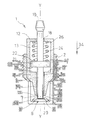
- Figure 1 shows a spark plug 1 with a housing 2, a center electrode 3 and an insulator 4 surrounding the center electrode 3.
- the housing 2 is at least associated with a ground electrode 6. Between a firing 7 of the Center electrode 3 and the ground electrode 6, a spark gap 8 is formed.
- the spark gap 8 is at least partially filled by a spacer 9.
- the Spacer 9 is on the one hand to the ground electrode 6 and on the other the ignition end 7, so that a distance between the ground electrode 6 and the Firing 7 always stays the same.
- the spark plug 1 is used to ignite a fuel-air mixture in Internal combustion engines used for vehicles.
- the housing 2 is in Conventionally, in a cylinder head of the internal combustion engine taken up, and consists of a metal.
- the housing 2 is initially designed as a hollow cylinder in cross-section, and is tapered at an end portion 10 oriented toward the firing end 7 Direction to the firing 7.
- the insulator 4 has an end 11 arranged at the firing end 7 and a thereto opposite closure end 12, and is designed as a hollow body.
- a receiving area 13 In the insulator 4 is a receiving area 13 and a guide portion 14 is inserted, which are formed concentrically to a central axis Y-Y.
- the receiving area 13 has a larger diameter than the guide portion 14 so that a Investment shoulder 16 is formed in a transition 17.
- the receiving area 13 extends from the closure end 12 to the transition 17.
- a wall of the Receiving area 13 is quadrangular seen to the transition 17 in cross section educated.
- the closure end 12 has a passage opening 18 to Carrying out an electrical connection 19.
- the guide portion 14 extends from the transition 17 until shortly before Firing end 7 of the center electrode 3, so that the firing end 7 from the guide area 14 stands out.
- a wall of the guide region 14 is of the transition 17th up to the end portion 10 of the housing 2 seen in cross section square and thicker formed as the wall of the receiving area 13.
- the wall of the Guide area 14 is in the further course in the direction of the firing end. 7 corresponding to the end portion 10 of the housing 2 conically configured and has a level 15 there. From level 15, the wall of the Guide section 14 conical towards the end 11.
- the center electrode 3 projects with a head end opposite the ignition end 7 21 in the receiving area 13 inside.
- the head end 21 is at the receiving area 13 adapted and has a slightly smaller diameter than the receiving area 13 on.
- the head end 21 has a bearing end 12 facing the bearing surface 22 and an opposite mating surface 23 on. With the support surface 22 the electrical connection 19 is connected so that a complete electrical Connection of the electrical connection 19 to the ignition 7 is.
- the electrical connection 19 can of course also in one piece with the Center electrode 3 to be made.
- a spring 24 In the receiving area 13 is a spring 24, preferably a coil spring arranged.
- the spring 24 is biased and is located at one end 26 at the Closure end 12 of the insulator 4 and with an opposite end 27th on the support surface 22 of the head end 21 at.
- the spring 24 is shown in the Embodiment by their investment in the closure end 12 of the insulator 4th electrically separated from both the terminal 19 and the center electrode 3.
- annular gap 25 Between the center electrode 3 and an inner wall of the guide portion 14 is in arranged an annular gap 25 in the illustrated embodiment.
- the ground electrode 6 is seen in cross-section U-shaped with U-legs 28 and a base web 29 configured.
- the U-legs 28 are on the housing 2 via the end portion 10 and thus connected to the cylinder head.
- the Ground electrode 6 completely surrounds the firing end 7 when viewed in cross-section.
- the spacer 9 is frustoconical in the illustrated embodiment designed. With a bearing surface 31, the spacing means 9 with the base web 29 and with a bearing surface 29 opposite the bearing surface 32 is the Distance means 9 connected to the ignition end 7.
- the spacer 9 is a ceramic pitch controller.
- the support surface 31 is seen in cross section larger than the abutment surface 32 and smaller than a length of the base web 29, so that corners 33 of the bearing surface 31 are spaced apart from the U-legs 28.
- the contact surface 32 seen in cross section is wider than the firing end. 7
- the spring 24 acts with a force acting in the direction of the firing end 7 force 34 so on the head end 21 of the center electrode 3, that the firing end 7 always frictionally is connected to the spacer means 9, even if the center electrode 3 after should show signs of wear for some time.
- the center electrode 3 is such arranged in the spark plug 1 that the center electrode 3 axially along the Central axis Y-Y is movable. Thus, in the preferred embodiment a self-adjusting spark plug 1 is shown.
- spark plug 1 electrical energy through the electrical connection 19 in known manner, sparks 36 are conventionally generated, the via the spacer 9 in the direction of the ground electrode 6 slide.
- the spark plug 1 acts in the preferred embodiment as a Surface discharge.
- spark plug 1 is advantageously achieved that the spark gap. 8 remains unchanged during the entire life of the spark plug 1, wherein even after a mileage of a motor vehicle engine of about 200,000 km the electric power delivery is unchanged.
Landscapes
- Spark Plugs (AREA)
Abstract
Description
Claims (9)
- Zündkerze mit einem Gehäuse (2), einer Mittelelektrode (3) und einem die Mittelelektrode (3) umgebenden Isolator (4), wobei dem Gehäuse (2) zumindest eine Massenelektrode (6) zugeordnet ist, und wobei ein Zündspalt (8) zwischen der Massenelektrode (6) und einem Zündende (7) der Mittelelektrode (3) ausgebildet ist,
dadurch gekennzeichnet, daß
in dem Zündspalt (8) ein Abstandsmittel (9) angeordnet ist, das zum einen an der Massenelektrode (6) und zum anderen an dem Zündende (7) derart anliegt, daß ein Abstand zwischen der Massenelektrode (6) und dem Zündende (7) stets gleich bleibt. - Zündkerze nach Anspruch 1,
dadurch gekennzeichnet, daß
das Abstandsmittel (9) kegelstumpfförmig ausgebildet ist. - Zündkerze nach Anspruch 1 oder 2,
dadurch gekennzeichnet, daß
das Abstandsmittel (9) mit einer Auflagefläche (31) im Querschnitt gesehen breiter als eine zur Auflagefläche (31) gegenüberliegende Anlagefläche (32) ausgebildet ist. - Zündkerze nach einem der vorhergehenden Ansprüche,
dadurch gekennzeichnet, daß
das Abstandsmittel (9) aus einem elektrisch nicht-leitenden Material besteht. - Zündkerze nach einem der vorhergehenden Ansprüche,
dadurch gekennzeichnet, daß
das Abstandsmittel (9) aus Keramik besteht. - Zündkerze nach einem der vorhergehenden Ansprüche,
dadurch gekennzeichnet, daß
die Massenelektrode (6) im Querschnitt gesehen u-förmig mit U-Schenkeln (28) und einem Basissteg (29) ausgestaltet ist. - Zündkerze nach einem der vorhergehenden Ansprüche,
dadurch gekennzeichnet, daß
die Massenelektrode (6) das Zündende (7) im Querschnitt gesehen umschließt. - Zündkerze nach einem der vorhergehenden Ansprüche,
dadurch gekennzeichnet, daß
die Mittelelektrode (3) mit ihrem Zündende (7) federkraftbedingt gegen das Abstandsmittel (9) gedrückt wird, so daß die Mittelelektrode (3) kraftschlüssig mit dem Abstandsmittel (9) verbunden ist. - Zündkerze nach einem der vorhergehenden Ansprüche,
dadurch gekennzeichnet, daß
die Mittelelektrode (3) derart angeordnet ist, daß diese axial beweglich entlang einer Mittelachse (Y-Y) ist.
Priority Applications (2)
| Application Number | Priority Date | Filing Date | Title |
|---|---|---|---|
| EP20040100005 EP1553671B1 (de) | 2004-01-05 | 2004-01-05 | Zündkerze |
| DE200450003751 DE502004003751D1 (de) | 2004-01-05 | 2004-01-05 | Zündkerze |
Applications Claiming Priority (1)
| Application Number | Priority Date | Filing Date | Title |
|---|---|---|---|
| EP20040100005 EP1553671B1 (de) | 2004-01-05 | 2004-01-05 | Zündkerze |
Publications (2)
| Publication Number | Publication Date |
|---|---|
| EP1553671A1 true EP1553671A1 (de) | 2005-07-13 |
| EP1553671B1 EP1553671B1 (de) | 2007-05-09 |
Family
ID=34585987
Family Applications (1)
| Application Number | Title | Priority Date | Filing Date |
|---|---|---|---|
| EP20040100005 Expired - Fee Related EP1553671B1 (de) | 2004-01-05 | 2004-01-05 | Zündkerze |
Country Status (2)
| Country | Link |
|---|---|
| EP (1) | EP1553671B1 (de) |
| DE (1) | DE502004003751D1 (de) |
Cited By (1)
| Publication number | Priority date | Publication date | Assignee | Title |
|---|---|---|---|---|
| US10675752B2 (en) | 2015-10-21 | 2020-06-09 | Fft Produktionssysteme Gmbh & Co. Kg | Absolute robot-assisted positioning method |
Citations (6)
| Publication number | Priority date | Publication date | Assignee | Title |
|---|---|---|---|---|
| US2548170A (en) * | 1948-12-30 | 1951-04-10 | Pure Oil Co | Spark plug |
| DE883817C (de) * | 1941-11-28 | 1953-07-20 | Nienburger Metallwarenfabrik A | Gleitfunkenzuendkerze |
| US4460847A (en) * | 1981-07-27 | 1984-07-17 | Champion Spark Plug Company | Spark plug |
| US4939409A (en) * | 1986-06-12 | 1990-07-03 | Robert Bosch Gmbh | Spark plug with a surface discharge section |
| WO1999031775A1 (en) * | 1997-12-17 | 1999-06-24 | Dawson Royalties Limited | Spark plug |
| JP2001006842A (ja) * | 1999-06-17 | 2001-01-12 | Aichi Mach Ind Co Ltd | スパークプラグの電極構造 |
-
2004
- 2004-01-05 DE DE200450003751 patent/DE502004003751D1/de not_active Expired - Lifetime
- 2004-01-05 EP EP20040100005 patent/EP1553671B1/de not_active Expired - Fee Related
Patent Citations (6)
| Publication number | Priority date | Publication date | Assignee | Title |
|---|---|---|---|---|
| DE883817C (de) * | 1941-11-28 | 1953-07-20 | Nienburger Metallwarenfabrik A | Gleitfunkenzuendkerze |
| US2548170A (en) * | 1948-12-30 | 1951-04-10 | Pure Oil Co | Spark plug |
| US4460847A (en) * | 1981-07-27 | 1984-07-17 | Champion Spark Plug Company | Spark plug |
| US4939409A (en) * | 1986-06-12 | 1990-07-03 | Robert Bosch Gmbh | Spark plug with a surface discharge section |
| WO1999031775A1 (en) * | 1997-12-17 | 1999-06-24 | Dawson Royalties Limited | Spark plug |
| JP2001006842A (ja) * | 1999-06-17 | 2001-01-12 | Aichi Mach Ind Co Ltd | スパークプラグの電極構造 |
Non-Patent Citations (1)
| Title |
|---|
| PATENT ABSTRACTS OF JAPAN vol. 2000, no. 16 8 May 2001 (2001-05-08) * |
Cited By (1)
| Publication number | Priority date | Publication date | Assignee | Title |
|---|---|---|---|---|
| US10675752B2 (en) | 2015-10-21 | 2020-06-09 | Fft Produktionssysteme Gmbh & Co. Kg | Absolute robot-assisted positioning method |
Also Published As
| Publication number | Publication date |
|---|---|
| EP1553671B1 (de) | 2007-05-09 |
| DE502004003751D1 (de) | 2007-06-21 |
Similar Documents
| Publication | Publication Date | Title |
|---|---|---|
| EP3281263B1 (de) | Zündkerze | |
| DE102010004851B4 (de) | Vorkammer-Zündkerze für eine mit Gas betriebene Brennkraftmaschine | |
| DE102013109278B4 (de) | Zündkerze für eine mit Gas betriebene Brennkraftmaschine | |
| DE102014111684B3 (de) | Koronazündeinrichtung | |
| DE102012111172B4 (de) | Korona-Zündeinrichtung | |
| EP0238520B1 (de) | Zündkerze mit gleitfunkenstrecke | |
| DE19743544A1 (de) | Zündeinrichtung für eine Brennkraftmaschine | |
| DE19611283C1 (de) | Zündkerzenstecker für einen Verbrennungsmotor | |
| DE102007050634A1 (de) | Zündkerze | |
| DE102012213939B4 (de) | Zündkerze | |
| DE202004006644U1 (de) | Elektrode | |
| WO1998026481A1 (de) | Zündkerze | |
| EP1553671B1 (de) | Zündkerze | |
| DE102010011739A1 (de) | Zündkerze und Verfahren zur Herstellung einer Zündkerze | |
| EP0073939A1 (de) | Hochspannungszündkerze | |
| DE2928018C2 (de) | Vorrichtung zum Zünden eines mageren Brennstoff-Luft-Gemischs | |
| DE102012110657B3 (de) | Koronazündeinrichtung | |
| DE102020105924A1 (de) | Fremd gezündete Hubkolben-Brennkraftmaschine mit einem Vorkammerzündsystem | |
| DE102006033578A1 (de) | Zündeinrichtung, insbesondere Zündkerze für eine Verbrennungskraftmaschine und Verfahren zur Positionierung von wenigstens einer Masseelektrode in der Zündeinrichtung | |
| DE102019122532A1 (de) | Vorkammerzündsystem für eine fremd gezündete Hubkolben-Brennkraftmaschine | |
| DE102013212298A1 (de) | Glühstiftkerze | |
| DE10119310B4 (de) | Gleitfunkenzündkerze | |
| DE4230447C2 (de) | Zündkerze | |
| DE10340042B4 (de) | Zündkerze | |
| DE102004030790B4 (de) | Zündkerze mit Zündkabel |
Legal Events
| Date | Code | Title | Description |
|---|---|---|---|
| PUAI | Public reference made under article 153(3) epc to a published international application that has entered the european phase |
Free format text: ORIGINAL CODE: 0009012 |
|
| AK | Designated contracting states |
Kind code of ref document: A1 Designated state(s): AT BE BG CH CY CZ DE DK EE ES FI FR GB GR HU IE IT LI LU MC NL PT RO SE SI SK TR |
|
| AX | Request for extension of the european patent |
Extension state: AL LT LV MK |
|
| 17P | Request for examination filed |
Effective date: 20060113 |
|
| AKX | Designation fees paid |
Designated state(s): DE FR GB |
|
| GRAP | Despatch of communication of intention to grant a patent |
Free format text: ORIGINAL CODE: EPIDOSNIGR1 |
|
| GRAS | Grant fee paid |
Free format text: ORIGINAL CODE: EPIDOSNIGR3 |
|
| GRAA | (expected) grant |
Free format text: ORIGINAL CODE: 0009210 |
|
| AK | Designated contracting states |
Kind code of ref document: B1 Designated state(s): DE FR GB |
|
| REG | Reference to a national code |
Ref country code: GB Ref legal event code: FG4D Free format text: NOT ENGLISH |
|
| REF | Corresponds to: |
Ref document number: 502004003751 Country of ref document: DE Date of ref document: 20070621 Kind code of ref document: P |
|
| GBT | Gb: translation of ep patent filed (gb section 77(6)(a)/1977) |
Effective date: 20070718 |
|
| ET | Fr: translation filed | ||
| PLBE | No opposition filed within time limit |
Free format text: ORIGINAL CODE: 0009261 |
|
| STAA | Information on the status of an ep patent application or granted ep patent |
Free format text: STATUS: NO OPPOSITION FILED WITHIN TIME LIMIT |
|
| 26N | No opposition filed |
Effective date: 20080212 |
|
| PGFP | Annual fee paid to national office [announced via postgrant information from national office to epo] |
Ref country code: GB Payment date: 20141230 Year of fee payment: 12 |
|
| PGFP | Annual fee paid to national office [announced via postgrant information from national office to epo] |
Ref country code: FR Payment date: 20141226 Year of fee payment: 12 |
|
| PGFP | Annual fee paid to national office [announced via postgrant information from national office to epo] |
Ref country code: DE Payment date: 20150126 Year of fee payment: 12 |
|
| REG | Reference to a national code |
Ref country code: DE Ref legal event code: R119 Ref document number: 502004003751 Country of ref document: DE |
|
| GBPC | Gb: european patent ceased through non-payment of renewal fee |
Effective date: 20160105 |
|
| REG | Reference to a national code |
Ref country code: FR Ref legal event code: ST Effective date: 20160930 |
|
| PG25 | Lapsed in a contracting state [announced via postgrant information from national office to epo] |
Ref country code: DE Free format text: LAPSE BECAUSE OF NON-PAYMENT OF DUE FEES Effective date: 20160802 Ref country code: GB Free format text: LAPSE BECAUSE OF NON-PAYMENT OF DUE FEES Effective date: 20160105 |
|
| PG25 | Lapsed in a contracting state [announced via postgrant information from national office to epo] |
Ref country code: FR Free format text: LAPSE BECAUSE OF NON-PAYMENT OF DUE FEES Effective date: 20160201 |