EP1553485B1 - Analyse et marquage d'image de document avec encodage de position - Google Patents
Analyse et marquage d'image de document avec encodage de position Download PDFInfo
- Publication number
- EP1553485B1 EP1553485B1 EP20050000084 EP05000084A EP1553485B1 EP 1553485 B1 EP1553485 B1 EP 1553485B1 EP 20050000084 EP20050000084 EP 20050000084 EP 05000084 A EP05000084 A EP 05000084A EP 1553485 B1 EP1553485 B1 EP 1553485B1
- Authority
- EP
- European Patent Office
- Prior art keywords
- image
- document
- maze pattern
- pixel
- labeling
- Prior art date
- Legal status (The legal status is an assumption and is not a legal conclusion. Google has not performed a legal analysis and makes no representation as to the accuracy of the status listed.)
- Not-in-force
Links
Images


Classifications
-
- G—PHYSICS
- G06—COMPUTING; CALCULATING OR COUNTING
- G06F—ELECTRIC DIGITAL DATA PROCESSING
- G06F17/00—Digital computing or data processing equipment or methods, specially adapted for specific functions
-
- G—PHYSICS
- G06—COMPUTING; CALCULATING OR COUNTING
- G06F—ELECTRIC DIGITAL DATA PROCESSING
- G06F3/00—Input arrangements for transferring data to be processed into a form capable of being handled by the computer; Output arrangements for transferring data from processing unit to output unit, e.g. interface arrangements
- G06F3/01—Input arrangements or combined input and output arrangements for interaction between user and computer
- G06F3/03—Arrangements for converting the position or the displacement of a member into a coded form
- G06F3/033—Pointing devices displaced or positioned by the user, e.g. mice, trackballs, pens or joysticks; Accessories therefor
- G06F3/0354—Pointing devices displaced or positioned by the user, e.g. mice, trackballs, pens or joysticks; Accessories therefor with detection of 2D relative movements between the device, or an operating part thereof, and a plane or surface, e.g. 2D mice, trackballs, pens or pucks
- G06F3/03542—Light pens for emitting or receiving light
-
- G—PHYSICS
- G06—COMPUTING; CALCULATING OR COUNTING
- G06F—ELECTRIC DIGITAL DATA PROCESSING
- G06F3/00—Input arrangements for transferring data to be processed into a form capable of being handled by the computer; Output arrangements for transferring data from processing unit to output unit, e.g. interface arrangements
- G06F3/01—Input arrangements or combined input and output arrangements for interaction between user and computer
- G06F3/03—Arrangements for converting the position or the displacement of a member into a coded form
- G06F3/0304—Detection arrangements using opto-electronic means
- G06F3/0317—Detection arrangements using opto-electronic means in co-operation with a patterned surface, e.g. absolute position or relative movement detection for an optical mouse or pen positioned with respect to a coded surface
- G06F3/0321—Detection arrangements using opto-electronic means in co-operation with a patterned surface, e.g. absolute position or relative movement detection for an optical mouse or pen positioned with respect to a coded surface by optically sensing the absolute position with respect to a regularly patterned surface forming a passive digitiser, e.g. pen optically detecting position indicative tags printed on a paper sheet
Definitions
- Embodiments of the invention relate to interaction between a positionally encoded medium and a digital pen. More particularly, embodiments of the invention relate to labeling images of documents, which contain positionally encoded information, based on a degree to which the document's content occludes the position-encoding information.
- One technique of capturing handwritten information is by using a pen whose location may be determined during writing.
- One pen that provides this capability is the Anoto pen by Anoto Inc.
- This pen functions by using a camera to capture an image of paper encoded with a predefined pattern.
- An example of the image pattern is shown in Figure 21 .
- This pattern is used by the Anoto pen (by Anoto Inc.) to determine a location of a pen on a piece of paper.
- it is unclear how efficient the determination of the location is with the system used by the Anoto pen.
- To provide efficient determination of the location of the captured image a system is needed that provides efficient decoding of the captured image.
- a user may mark the document by moving a pen tip with respect to the document.
- the path of the pen tip may comprise a plurality of strokes, where each stroke corresponds to a series of captured images.
- Portions of the positionally encoded information may be occluded by the document's content, such as text and/or graphics.
- the document's content such as text and/or graphics.
- the area's location within the document can be determined efficiently without a need to perform costly computations to determine the location.
- the document's content occludes a relatively large amount of the position-encoding information in an area of the document, however, more computationally intensive techniques may need to be used to determine the area's location within the document.
- US 2004/001608 A1 discloses an image processor and corresponding image processing method.
- a detector selects image blocks for further analysis in order to detect the presence of a detection watermark in a host image and its orientation.
- the detector identifies portions of the image that are likely to have the highest watermark signal to noise ratio.
- the detector divides the input image into blocks and analyses each blocks based on predetermined metrics. It then ranks the blocks according to these metrics. These metrics include sample variance in a candidate block and a measure of the edges in the block.
- the detector combines these metrics for each candidate block to compute a rank representing the probability that it contains a recoverable watermark signal.
- Embodiments of the invention relate to analyzing document images, which contain positionally encoded information, such as maze patterns, and labeling the captured images.
- the results of such document analysis may be used for efficiently determining a location of a camera-captured image within a positionally encoded document.
- a system includes an image capture module and an analysis-and-labeling module.
- the analysis-and-labeling module receives, as input, captured-image data output by the image-capture module and off-line training data; performs analysis-and-labeling processing; and outputs image-label information.
- Printed documents are watermarked with maze patterns. Such maze patterns may be occluded by a document's content, such as text. Depending on the degree of such occlusion, it may not be possible to extract enough position-encoding bits from a camera-captured image to determine the camera-captured image's location within the document.
- Watermarked document images are analyzed and labeled.
- the analysis and labeling relates to an ability to determine the x-y position within a watermarked document based on the degree of visibility of the maze pattern in a particular location within the document.
- aspects of the present invention relate to determining the location of a captured image in relation to a larger image.
- the location determination method and system described herein may be used in combination with a multi-function pen.
- the following is separated by subheadings for the benefit of the reader.
- the subheadings include: terms, general-purpose computer, image capturing pen, encoding of array, decoding, error correction, location determination, and analysis and labeling of camera-captured images.
- Pen - any writing implement that may or may not include the ability to store ink.
- a stylus with no ink capability may be used as a pen in accordance with embodiments of the present invention.
- Camera - an image capture system that may capture an image from paper or any other medium.
- Figure 1 is a functional block diagram of an example of a conventional general-purpose digital computing environment that can be used to implement various aspects of the present invention.
- a computer 100 includes a processing unit 110, a system memory 120, and a system bus 130 that couples various system components including the system memory to the processing unit 110.
- the system bus 130 may be any of several types of bus structures including a memory bus or memory controller, a peripheral bus, and a local bus using any of a variety of bus architectures.
- the system memory 120 includes read only memory (ROM) 140 and random access memory (RAM) 150.
- a basic input/output system 160 (BIOS), containing the basic routines that help to transfer information between elements within the computer 100, such as during start-up, is stored in the ROM 140.
- the computer 100 also includes a hard disk drive 170 for reading from and writing to a hard disk (not shown), a magnetic disk drive 180 for reading from or writing to a removable magnetic disk 190, and an optical disk drive 191 for reading from or writing to a removable optical disk 192 such as a CD ROM or other optical media.
- the hard disk drive 170, magnetic disk drive 180, and optical disk drive 191 are connected to the system bus 130 by a hard disk drive interface 192, a magnetic disk drive interface 193, and an optical disk drive interface 194, respectively.
- the drives and their associated computer-readable media provide nonvolatile storage of computer readable instructions, data structures, program modules and other data for the personal computer 100. It will be appreciated by those skilled in the art that other types of computer readable media that can store data that is accessible by a computer, such as magnetic cassettes, flash memory cards, digital video disks, Bernoulli cartridges, random access memories (RAMs), read only memories (ROMs), and the like, may also be used in the example operating environment.
- RAMs random access memories
- ROMs read only memories
- a number of program modules can be stored on the hard disk drive 170, magnetic disk 190, optical disk 192, ROM 140 or RAM 150, including an operating system 195, one or more application programs 196, other program modules 197, and program data 198.
- a user can enter commands and information into the computer 100 through input devices such as a keyboard 101 and pointing device 102.
- Other input devices may include a microphone, joystick, game pad, satellite dish, scanner or the like.
- These and other input devices are often connected to the processing unit 110 through a serial port interface 106 that is coupled to the system bus, but may be connected by other interfaces, such as a parallel port, game port or a universal serial bus (USB).
- USB universal serial bus
- these devices may be coupled directly to the system bus 130 via an appropriate interface (not shown).
- a monitor 107 or other type of display device is also connected to the system bus 130 via an interface, such as a video adapter 108.
- personal computers typically include other peripheral output devices (not shown), such as speakers and printers.
- a pen digitizer 165 and accompanying pen or stylus 166 are provided in order to digitally capture freehand input.
- the pen digitizer 165 may be coupled to the processing unit 110 directly, via a parallel port or other interface and the system bus 130 as known in the art.
- the digitizer 165 is shown apart from the monitor 107, it is preferred that the usable input area of the digitizer 165 be co-extensive with the display area of the monitor 107. Further still, the digitizer 165 may be integrated in the monitor 107, or may exist as a separate device overlaying or otherwise appended to the monitor 107.
- the computer 100 can operate in a networked environment using logical connections to one or more remote computers, such as a remote computer 109.
- the remote computer 109 can be a server, a router, a network PC, a peer device or other common network node, and typically includes many or all of the elements described above relative to the computer 100, although only a memory storage device 111 has been illustrated in Figure 1 .
- the logical connections depicted in Figure 1 include a local area network (LAN) 112 and a wide area network (WAN) 113.
- LAN local area network
- WAN wide area network
- the computer 100 When used in a LAN networking environment, the computer 100 is connected to the local network 112 through a network interface or adapter 114. When used in a WAN networking environment, the personal computer 100 typically includes a modem 115 or other means for establishing a communications over the wide area network 113, such as the Internet.
- the modem 115 which may be internal or external, is connected to the system bus 130 via the serial port interface 106.
- program modules depicted relative to the personal computer 100, or portions thereof, may be stored in the remote memory storage device.
- network connections shown are illustrative and other techniques for establishing a communications link between the computers can be used.
- the existence of any of various well-known protocols such as TCP/IP, Ethernet, FTP, HTTP, Bluetooth, IEEE 802.11x and the like is presumed, and the system can be operated in a client-server configuration to permit a user to retrieve web pages from a web-based server.
- Any of various conventional web browsers can be used to display and manipulate data on web pages.
- aspects of the present invention include placing an encoded data stream in a displayed form that represents the encoded data stream.
- the displayed form may be printed paper (or other physical medium) or may be a display projecting the encoded data stream in conjunction with another image or set of images.
- the encoded data stream may be represented as a physical graphical image on the paper or a graphical image overlying the displayed image (e.g., representing the text of a document) or may be a physical (non-modifiable) graphical image on a display screen (so any image portion captured by a pen is locatable on the display screen).
- the pen may be an ink pen writing on paper.
- the pen may be a stylus with the user writing on the surface of a computer display. Any interaction may be provided back to the system with knowledge of the encoded image on the document or supporting the document displayed on the computer screen.
- the displayed or printed image may be a watermark associated with the blank or content-rich paper or may be a watermark associated with a displayed image or a fixed coding overlying a screen or built into a screen.
- FIGS 2A and 2B show an illustrative example of pen 201 with a camera 203.
- Pen 201 includes a tip 202 that may or may not include an ink reservoir.
- Camera 203 captures an image 204 from surface 207.
- Pen 201 may further include additional sensors and/or processors as represented in broken box 206. These sensors and/or processors 206 may also include the ability to transmit information to another pen 201 and/or a personal computer (for example, via Bluetooth or other wireless protocols).
- Figure 2B represents an image as viewed by camera 203.
- the field of view of camera 203 i.e., the resolution of the image sensor of the camera
- a captured image 32 pixels by 32 pixels
- Figure 2B shows a field of view of 32 pixels long by 32 pixels wide.
- the size of N is adjustable, such that a larger N corresponds to a higher image resolution.
- the field of view of the camera 203 is shown as a square for illustrative purposes here, the field of view may include other shapes as is known in the art.
- the images captured by camera 203 may be defined as a sequence of image frames ⁇ I i ⁇ , where I i is captured by the pen 201 at sampling time t i .
- the sampling rate may be large or small, depending on system configuration and performance requirement.
- the size of the captured image frame may be large or small, depending on system configuration and performance requirement.
- the image captured by camera 203 may be used directly by the processing system or may undergo pre-filtering. This pre-filtering may occur in pen 201 or may occur outside of pen 201 (for example, in a personal computer).
- the image size of Figure 2B is 32x32 pixels. If each encoding unit size is 3x3 pixels, then the number of captured encoded units would be approximately 100 units. If the encoding unit size is 5x5 pixels, then the number of captured encoded units is approximately 36.
- Figure 2A also shows the image plane 209 on which an image 210 of the pattern from location 204 is formed.
- Light received from the pattern on the object plane 207 is focused by lens 208.
- Lens 208 may be a single lens or a multi-part lens system, but is represented here as a single lens for simplicity.
- Image capturing sensor 211 captures the image 210.
- the image sensor 211 may be large enough to capture the image 210.
- the image sensor 211 may be large enough to capture an image of the pen tip 202 at location 212.
- the image at location 212 is referred to as the virtual pen tip. It is noted that the virtual pen tip location with respect to image sensor 211 is fixed because of the constant relationship between the pen tip, the lens 208, and the image sensor 211.
- F' S ⁇ P by matching the captured image with the corresponding real image on paper.
- "Refine” means to get a more precise estimation of the transformation F S ⁇ P by a type of optimization algorithm referred to as a recursive method.
- the recursive method treats the matrix F' S ⁇ P as the initial value.
- the refined estimation describes the transformation between S and P more precisely.
- a location of the virtual pen tip L virtual-pentip may be determined.
- L virtual-pentip one can get a more accurate estimation of L pentip .
- an accurate location of virtual pen tip L virtual-pentip may be determined.
- a two-dimensional array may be constructed by folding a one-dimensional sequence. Any portion of the two-dimensional array containing a large enough number of bits may be used to determine its location in the complete two-dimensional array. However, it may be necessary to determine the location from a captured image or a few captured images. So as to minimize the possibility of a captured image portion being associated with two or more locations in the two-dimensional array, a non-repeating sequence may be used to create the array.
- One property of a created sequence is that the sequence does not repeat over a length (or window) n . The following describes the creation of the one-dimensional sequence then the folding of the sequence into an array.
- a sequence of numbers may be used as the starting point of the encoding system.
- a sequence (also referred to as an m -sequence) may be represented as a q-element set in field F q .
- q p n where n ⁇ 1 and p is a prime number.
- the sequence or m -sequence may be generated by a variety of different techniques including, but not limited to, polynomial division. Using polynomial division, the sequence may be defined as follows: R l x P n x
- P n (x) is a primitive polynomial of degree n in field F q [x] (having q n elements).
- R i (x) is a nonzero polynomial of degree l (where l ⁇ n ) in field F q [x].
- the sequence may be created using an iterative procedure with two steps: first, dividing the two polynomials (resulting in an element of field F q ) and, second, multiplying the remainder by x .
- the computation stops when the output begins to repeat. This process may be implemented using a linear feedback shift register as set forth in an article by Douglas W.
- the array (or m -array) that may be used to create the image (of which a portion may be captured by the camera) is an extension of the one-dimensional sequence or m- sequence.
- n 1 ⁇ n 2 window shifts through a period of A, all the nonzero n 1 ⁇ n 2 matrices over F q appear once and only once.
- This property is also referred to as a "window property" in that each window is unique.
- a widow may then be expressed as an array of period ( m 1 , m 2 ) (with m 1 and m 2 being the horizontal and vertical number of bits present in the array) and order (n 1 , n 2 ).
- a binary array may be constructed by folding the sequence.
- one may start with a predetermined size of the space that one wants to cover (for example, one sheet of paper, 30 sheets of paper or the size of a computer monitor), determine the area ( m 1 ⁇ m 2 ), then use the size to let L ⁇ m 1 ⁇ m 2 , where L 2 n - 1.
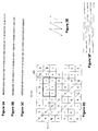
- Figures 3A through 3C show three different sequences. Each of these may be folded into the array shown as Figure 3D .
- the three different folding methods are shown as the overlay in Figure 3D and as the raster paths in Figures 3E and 3F .
- This folding approach may be alternatively expressed as laying the sequence on the diagonal of the array, then continuing from the opposite edge when an edge is reached.
- Figure 4A shows sample encoding techniques that may be used to encode the array of Figure 3D . It is appreciated that other encoding techniques may be used. For example, an alternative coding technique is shown in Figure 11 .
- a first bit 401 (for example, "1") is represented by a column of dark ink.
- a second bit 402 (for example, "0") is represented by a row of dark ink.
- any color ink may be used to represent the various bits. The only requirement in the color of the ink chosen is that it provides a significant contrast with the background of the medium to be differentiable by an image capture system.
- the bits in Figure 4A are represented by a 3x3 matrix of cells. The size of the matrix may be modified to be any size as based on the size and resolution of an image capture system.
- Alternative representation of bits 0 and 1 are shown in Figures 4C-4E .
- Figure 4C shows bit representations occupying two rows or columns in an interleaved arrangement.
- Figure 4D shows an alternative arrangement of the pixels in rows and columns in a dashed form.
- Figure 4E shows pixel representations in columns and rows in an irregular spacing format (e.g., two dark dots followed by a blank dot).
- more than one pixel or dot is used to represent a bit.
- Using a single pixel (or bit) to represent a bit is fragile. Dust, creases in paper, non-planar surfaces, and the like create difficulties in reading single bit representations of data units.
- different approaches may be used to graphically represent the array on a surface. Some approaches are shown in Figures 4C through 4E . It is appreciated that other approaches may be used as well.
- One approach is set forth in Figure 11 using only space-shifted dots.
- a bit stream is used to create the graphical pattern 403 of Figure 4B .
- Graphical pattern 403 includes 12 rows and 18 columns. The rows and columns are formed by a bit stream that is converted into a graphical representation using bit representations 401 and 402.
- Figure 4B may be viewed as having the following bit representation: 0 1 0 1 0 1 1 1 0 1 1 0 1 1 0 0 1 0 0 1 0 0 0 0 1 0 1 0 1 1 1 0 1 1 0 0 0 0 0 1 1 1 0 1 0 0 0 0
- pen 201 may utilize a pressure sensor as pen 201 is pressed against paper and pen 201 traverses a document on the paper.
- the image is then processed to determine the orientation of the captured image with respect to the complete representation of the encoded image and extract the bits that make up the captured image.
- the image captured by a camera 601 may be analyzed and its orientation determined so as to be interpretable as to the position actually represented by the image 601.
- image 601 is reviewed to determine the angle ⁇ needed to rotate the image so that the pixels are horizontally and vertically aligned.
- alternative grid alignments are possible including a rotation of the underlying grid to a non-horizontal and vertical arrangement (for example, 45 degrees).
- Using a non-horizontal and vertical arrangement may provide the probable benefit of eliminating visual distractions from the user, as users may tend to notice horizontal and vertical patterns before others.
- the orientation of the grid (horizontal and vertical and any other rotation of the underlying grid) is referred to collectively as the predefined grid orientation.
- image 601 is analyzed to determine which corner is missing.
- the rotation amount is shown by the equation in Figure 7 .
- angle ⁇ is first determined by the layout of the pixels to arrive at a horizontal and vertical (or other predefined grid orientation) arrangement of the pixels and the image is rotated as shown in 602.
- An analysis is then conducted to determine the missing corner and the image 602 rotated to the image 603 to set up the image for decoding.
- the image is rotated 90 degrees counterclockwise so that image 603 has the correct orientation and can be used for decoding.
- rotation angle ⁇ may be applied before or after rotation of the image 601 to account for the missing corner. It is also appreciated that by considering noise in the captured image, all four types of corners may be present. We may count the number of corners of each type and choose the type that has the least number as the corner type that is missing.
- the code in image 603 is read out and correlated with the original bit stream used to create image 403.
- the correlation may be performed in a number of ways. For example, it may be performed by a recursive approach in which a recovered bit stream is compared against all other bit stream fragments within the original bit stream. Second, a statistical analysis may be performed between the recovered bit stream and the original bit stream, for example, by using a Hamming distance between the two bit streams. It is appreciated that a variety of approaches may be used to determine the location of the recovered bit stream within the original bit stream.
- the image capture system may need to function with non-sequential bits extracted from the image. The following represents a method for operating with non-sequential bits from the image.
- the location s of the K bits is just the number of cyclic shifts of I so that b 0 is shifted to the beginning of the sequence.
- T the cyclic shift operator.
- the polynomials modulo P n ( x ) form a field. It is guaranteed that x s ⁇ r 0 + r 1 x + ⁇ r n -1 x n-1 mod( P n ( x )). Therefore, we may find ( r 0 , r 1 , ⁇ , r n -1 ) and then solve for s .
- r t b ⁇ t ⁇ M ⁇ - 1
- M ⁇ is any non-degenerate n ⁇ n sub-matrix of M and b ⁇ is the corresponding sub-vector of b .
- the Hamming distance between b t and r t M, or the number of error bits associated with r should be minimal, where r is computed via equation (4). Repeating the process for several times, it is likely that the correct r that results in the minimal error bits can be identified.
- the system then may move on to process the next captured image.
- information about previous locations of the pen can be taken into consideration. That is, for each captured image, a destination area where the pen may be expected next can be identified. For example, if the user has not lifted the pen between two image captures by the camera, the location of the pen as determined by the second image capture should not be too far away from the first location.
- Each r that is associated with the minimum number of error bits can then be checked to see if the location s computed from r satisfies the local constraint, i.e., whether the location is within the destination area specified.
- the decoding process fails.
- Figure 8 depicts a process that may be used to determine a location in a sequence (or m -sequence) of a captured image.
- a data stream relating to a captured image is received.
- corresponding columns are extracted from A and a matrix M is constructed.
- step 803 n independent column vectors are randomly selected from the matrix M and vector r is determined by solving equation (4). This process is performed Q times (for example, 100 times) in step 804. The determination of the number of loop times is discussed in the section Loop Times Calculation.
- r is sorted according to its associated number of error bits.
- the sorting can be done using a variety of sorting algorithms as known in the art. For example, a selection sorting algorithm may be used. The selection sorting algorithm is beneficial when the number Q is not large. However, if Q becomes large, other sorting algorithms (for example, a merge sort) that handle larger numbers of items more efficiently may be used.
- step 806 determines in step 806 whether error correction was performed successfully, by checking whether multiple r 's are associated with the minimum number of error bits. If yes, an error is returned in step 809, indicating the decoding process failed. If not, the position s of the extracted bits in the sequence (or m- sequence) is calculated in step 807, for example, by using the Pohig-Hellman-Silver algorithm.
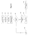
- Figure 9 shows a process for determining the location of a pen tip.
- the input is an image captured by a camera and the output may be a position coordinates of the pen tip. Also, the output may include (or not) other information such as a rotation angle of the captured image.
- step 901 an image is received from a camera.
- the received image may be optionally preprocessed in step 902 (as shown by the broken outline of step 902) to adjust the contrast between the light and dark pixels and the like.
- step 903 the image is analyzed to determine the bit stream within it.
- n bits are randomly selected from the bit stream for multiple times and the location of the received bit stream within the original sequence (or m- sequence) is determined.
- step 904 the location of the pen tip may be determined in step 905.
- Figure 10 gives more details about 903 and 904 and shows the approach to extract the bit stream within a captured image.
- an image is received from the camera in step 1001.
- the image then may optionally undergo image preprocessing in step 1002 (as shown by the broken outline of step 1002).
- the pattern is extracted in step 1003.
- pixels on the various lines may be extracted to find the orientation of the pattern and the angle ⁇ .
- step 1004 the received image is analyzed in step 1004 to determine the underlying grid lines. If grid lines are found in step 1005, then the code is extracted from the pattern in step 1006. The code is then decoded in step 1007 and the location of the pen tip is determined in step 1008. If no grid lines were found in step 1005, then an error is returned in step 1009.
- Embodiments of the invention relate to analyzing document images, which contain positionally encoded information, such as maze patterns, and labeling the images.
- the results of such document analysis may be used for efficiently determining a location of a camera-captured image within a positionally encoded document.
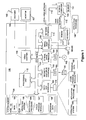
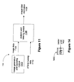
- a system 1100 in accordance with various embodiments of the invention, includes an image-generation-and-capturing module 1102 and an analysis-and-labeling module 1106. Suitable techniques for capturing images for subsequent analysis and labeling are discussed above in section III, entitled Image Capturing Pen, and below in this section and in section VIII.A, entitled Generating Watermarked Gray-Scale Document Images.
- the analysis-and-labeling module 1106 receives, as input, image data 1104 output by the image-generation-and-capturing module 1102 and off-line training data 1110; performs analysis-and-labeling processing, as discussed in more detail below; and outputs image-label information 1108.
- the size of the camera 203's captured image is 32*32 pixels.
- the order of the embedded m-array, which is used for positionally encoding positions on the surface 207, is 36, namely, the size of the m-array is (2 18 +1)*(2 18 -1). Therefore, to decode a unique x-y position from a sub-block m-array, the number of bits of a sub-block used for determining a position on the surface 207 should be at least 36.
- printed documents are watermarked with maze patterns.
- maze patterns may be occluded by a document's content, such as text. Depending on the degree of such occlusion, it may not be possible to extract enough m-array bits from a camera-captured image to determine the camera-captured image's location within the document.
- watermarked document images are analyzed and labeled.
- the analysis and labeling relates to an ability to determine the x-y position within a watermarked document based on the degree of visibility of the maze pattern cells in a particular location within the document.
- Figure 12 depicts steps for generating a watermarked gray-scale document image, which may be analyzed and labeled in accordance with various embodiments of the invention.
- Document images are obtained, such as by rendering an electronic document to a bitmap corresponding to a printed document, as shown at 1200 and 1204, or by scanning a paper document, as shown at 1202 and 1206.
- the bitmaps are then re-sampled to an appropriate resolution, as shown at 1208.
- Determination of the resolution is based on the following considerations: (1) the resolution of the document image shouldn't be less than that of the captured image, because when the location of the captured image cannot be determined by m-array decoding, the captured image will be matched with the watermarked gray-scale document image in order to determine the location; (2) one printed maze pattern cell should be mapped to an integer number of document image pixels so that the matching algorithm can work effectively. For example, if the resolution of the camera is 0.15mm/pixel, i.e. 0.15mm in the physical world is mapped to one camera pixel, the printed maze pattern cell size is 0.45mm*0.45mm, i.e. a printed maze pattern cell is mapped to 3*3 pixels on the camera sensor, the resolution of the document image should also be set to 0.15mm/pixel so that a printed maze pattern cell will be mapped to a 3*3 pixel area in the document image.
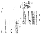
- Figure 13 depicts an image of a portion of a document's content 1300, a portion of a positionally encoded maze pattern 1302, the content and the maze pattern combined 1304, and a zoomed-in view of a portion of the content and the maze pattern 1306 showing: (1) a location at which a maze pattern cell is not visible because it is occluded by overlaid text 1308, and (2) a location at which a maze pattern cell is not occluded by document content and is, therefore, visible 1310.
- document images are analyzed by dividing the image into relatively small blocks having substantially the same size as maze pattern cells; determining whether these small blocks are occluded by document content, such as document text; and, for each pixel, counting the number of completely visible blocks in a neighboring window with the pixel as the center of the window; and labeling the pixel based on the number.
- the neighboring window may have substantially the same size as the size of the camera 203's captured image, i.e. 32 by 32 pixels.
- the aforementioned process doesn't require the gray-scale document image to be watermarked, i.e. content combined with the maze patterns.
- analyzing the occlusion of the maze pattern cells by document content is equivalent to analyzing the occlusion of the blocks by document content.
- Figure 14 shows an example of such a 32 by 32 pixel neighboring window 1400 and its center pixel 1402.
- the pixels of document images may be labeled as one of four types:
- the location of the image within a document may be uniquely determined by m-array decoding.
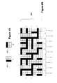
- Figure 15 shows the document analysis result of an example document wherein areas of the document are colored (or shaded) differently to represent which type (i.e, type I, II, III, or IV) the portion of the document has been labeled with based on the amount of maze-pattern cells that are visible in the 32 by 32 neighboring window of each pixel.
- type i.e, type I, II, III, or IV
- Figure 16 depicts a case in which the captured image is rotated by 45 degrees. This is the worst-case scenario where a maximum of 17.2% of the visible maze pattern cells may have been lost.
- a pixel is labeled as type I or II, there should be a sufficient number of visible maze pattern cells no matter at which angle the camera may have captured an image, to determine the x-y position with m-array decoding. Consequently, if a captured image fails to be decoded, it is most likely that it is located at type III or IV areas.
- a search algorithm may be used for determining the location of images, such as in the type III and IV pixel areas, within the document. Using such a search algorithm only on type III and IV areas decreases the computing cost for determining the location of images relative to using the search algorithm for substantially all parts of the document. For example, in the example document of Figure 15 , only 13.7% of the area is labeled as type III (11.1%) or type IV (2.6%). The computation cost associated with searching the entire document is much higher than that of searching only the type III and IV areas. In one implementation, it may take more than 10 seconds to search the entire document, whereas less than 1 second is needed to search type III and IV areas only. Document image analysis decreases the computation cost greatly.
- Camera-captured images may also be labeled with the four types discussed above in section VIII.B., entitled Document Image Analysis and Labeling.
- a determination may be made as to whether a camera-captured image contains substantially only positionally encoded maze patterns. Stated differently, a determination may be made as to whether or not the image is a type I image. This initial determination will be discussed in more detail below.
- a positionally encoded maze pattern of the camera-captured image may be analyzed to determine a number of position-encoding bits that can be extracted from the image.
- the parameters of maze pattern grid lines scale and rotation along each dimension, i.e. affine transform) are first calculated, and then the original direction (or quadrant) in which the maze pattern is embedded is determined. Consequently, the m-array bits information is determined based on the grid lines and bar directions.
- the image is labeled as type II; if between approximately 36 and 60 bits are extracted, the image is labeled as type III; and, if fewer than approximately 36 bits are extracted, then the image is labeled as type IV.
- a thresholding algorithm which is discussed below in section IX.B., entitled Thresholding Algorithm, may be used to separate the maze pattern areas from text areas. Then, images may be labeled based on the number of extracted bits.
- the extracted bits from type I, II, and III may be used for determining the camera-captured image's x-y position within a larger document. Position-determination processing of this type may be omitted for Type IV images because they do not contain enough bits for x-y position decoding.
- SIGIH support interval of gradient image histogram
- a first step of feature extraction is a gradient operator, such as the Sobel edge operator or another gradient operator, may be used to obtain gradient images.
- the two convolutional kernels, 1700 and 1702 form the Sobel edge operator.
- each pixel in an image is convolved with both of the convolutional kernels 1700 and 1702.
- One kernel responds maximally to a generally vertical edge and the other kernel responds maximally to a horizontal edge.
- a "vector sum" value of the two convolutions is taken as the output value for a particular pixel. The result is a gradient image.
- a histogram of the gradient image produced by the gradient operator may be calculated.
- the support interval of the gradient image histogram (SIGIH) may then be obtained from the histogram of the gradient image.
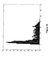
- Figure 18 shows a histogram of the gradient image of a captured image containing only maze patterns.
- the SIGIH feature is 17, which is the largest number along the x-axis to have a non-zero value, for the histogram of Figure 17 .
- Figure 19 shows a histogram of the gradient image of a captured image containing document content, such as text and/or one or more drawings.
- the SIGIH feature is 44 for the histogram of Figure 19 .
- a thresholding algorithm for determining whether an image is type I or not, in accordance with various embodiments of the invention, may be divided into 2 sessions: (1) off-line training; and (2) on-line labeling.
- the SIGIH feature may be calculated for a relatively large number of images with known labels (i.e., types I, II, III, or IV).
- the SIGIH of pure-maze-pattern images is often lower than the SIGIH for images of other types.
- An optimal threshold ⁇ may be selected based on the results of processing the training data. For substantially all pure-maze-pattern images in the training set, their SIGIH are less than ⁇ , and for substantially all non-pure-maze-pattem images, their SIGIH are greater than ⁇ .
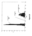
- Figure 20 shows an example result of off-line training in which ⁇ , an optimal threshold 2004, is selected to be 32. Also shown are histogram bars 2002 corresponding to pure-maze-pattern images and histogram bars 2006 corresponding to non-pure-maze-pattern images (i.e., images that include document content).
- each captured image's SIGIH is calculated. If the SIGIH is smaller than ⁇ , then the image is labeled as a type I image. Otherwise, if the SIGIH is greater than ⁇ , the image is labeled as a type other than type I (i.e., types II, III, and IV).
Claims (12)
- Procédé d'étiquetage d'une image contenant un motif de labyrinthe à position codée (403) pour indiquer une quantité d'information de position codée qui peut être extraite de l'image, l'image étant une image de document, le motif de labyrinthe comprenant une pluralité de cellules de motif de labyrinthe, le procédé comprenant :l'obtention (1102) de l'image, l'image contenant des pixels ; etl'étiquetage (1106) de l'image comme étant d'un type sélectionné parmi au moins : un premier type (1500) contenant pratiquement uniquement un motif de labyrinthe à position codée et pratiquement aucun contenu de document, et un deuxième type (1502, 1504, 1506) contenant un contenu de document qui occlut au moins une partie du motif de labyrinthe à position codée, dans lequel ledit étiquetage comprend l'analyse de l'image par :division de l'image en blocs ayant pratiquement la même taille que des cellules à motif de labyrinthe ;détermination du fait que les blocs sont ou non occlus par un contenu de document ;comptage, pour chaque pixel, d'un nombre de blocs complètement visibles dans une fenêtre avoisinant le pixel (1400) avec le pixel respectif de l'image considérée comme centre (1402) de la fenêtre avoisinant le pixel ; etétiquetage du pixel de l'image sur base dudit nombre.
- Procédé selon la revendication 1, dans lequel l'obtention de l'image comprend en outre : la restitution d'un document électronique dans une représentation bitmap correspondant à un document imprimé.
- Procédé selon la revendication 1, dans lequel l'obtention de l'image comprend en outre : le traitement d'un document papier scanné.
- Procédé selon la revendication 1, dans lequel le deuxième type est divisé en une pluralité de sous-types qui représentent différents degrés d'occlusion du motif de labyrinthe à position codée par le contenu de document.
- Système d'étiquetage d'une image contenant un motif de labyrinthe à position codée (403) pour indiquer une quantité d'information de position codée qui peut être extraite de l'image, le motif de labyrinthe comprenant une pluralité de cellules de motif de labyrinthe, l'image étant une image de document, le système comprenant :un module de génération et de capture d'image (1102) qui obtient l'image, l'image comprenant des pixels ; etun module d'analyse et d'étiquetage (1106) qui étiquette l'image comme étant d'un type sélectionné parmi au moins : un premier type (1500) contenant pratiquement uniquement un motif de labyrinthe à position codée et pratiquement aucun contenu de document, et un deuxième type (1502, 1504, 1506) contenant un contenu de document qui occlut au moins une partie du motif de labyrinthe à position codée, dans lequel l'étiquetage de l'image comprend l'analyse de l'image par :division de l'image en blocs ayant pratiquement la même taille que des cellules à motif de labyrinthe ;détermination du fait que les blocs sont ou non occlus par un contenu de document ;comptage, pour chaque pixel, d'un nombre de blocs complètement visibles dans une fenêtre avoisinant le pixel (1400) avec le pixel respectif de l'image considérée comme centre (1402) de la fenêtre avoisinant le pixel ; etétiquetage du pixel de l'image sur base dudit nombre.
- Système selon la revendication 5, dans lequel le module de génération et de capture d'image restitue un document électronique dans une représentation bitmap correspondant à un document imprimé.
- Système selon la revendication 5, dans lequel le module de génération et de capture d'image traite un document papier scanné.
- Système selon la revendication 5, dans lequel le deuxième type est divisé en une pluralité de sous-types qui représentent différents degrés d'occlusion du motif de labyrinthe à position codée par le contenu de document.
- Support lisible par un ordinateur contenant des instructions lisibles par un ordinateur pour étiqueter une image contenant un motif de labyrinthe à position codée (403) pour indiquer une quantité d'information de position codée qui peut être extraite de l'image, le motif de labyrinthe comprenant une pluralité de cellules de motif de labyrinthe, l'image étant une image de document, l'étiquetage étant exécuté en mettant en oeuvre les étapes comprenant :l'obtention (1102) de l'image, l'image contenant des pixels ; etl'étiquetage (1106) de l'image comme étant d'un type sélectionné parmi au moins : un premier type (1500) contenant pratiquement uniquement un motif de labyrinthe à position codée et pratiquement aucun contenu de document, et un deuxième type (1502, 1504, 1506) contenant un contenu de document qui occlut au moins une partie du motif de labyrinthe à position codée, dans lequel ledit étiquetage comprend l'analyse de l'image par :division de l'image en blocs ayant pratiquement la même taille que des cellules à motif de labyrinthe ;détermination du fait que les blocs sont ou non occlus par un contenu de document ;comptage, pour chaque pixel, d'un nombre de blocs complètement visibles dans une fenêtre avoisinant le pixel (1400) avec le pixel respectif de l'image considérée comme centre (1402) de la fenêtre avoisinant le pixel ; etétiquetage du pixel de l'image sur base dudit nombre.
- Support lisible par un ordinateur selon la revendication 9, dans lequel l'obtention de l'image comprend en outre : la restitution d'un document électronique dans une représentation bitmap correspondant à un document imprimé.
- Support lisible par un ordinateur selon la revendication 9, dans lequel l'obtention de l'image comprend en outre : le traitement d'un document papier scanné.
- Support lisible par un ordinateur selon la revendication 9, dans lequel le deuxième type est divisé en une pluralité de sous-types qui représentent différents degrés d'occlusion du motif de labyrinthe à position codée par le contenu de document.
Applications Claiming Priority (2)
| Application Number | Priority Date | Filing Date | Title |
|---|---|---|---|
| US753176 | 1985-07-09 | ||
| US10/753,176 US7581171B2 (en) | 2004-01-06 | 2004-01-06 | Positionally encoded document image analysis and labeling |
Publications (3)
| Publication Number | Publication Date |
|---|---|
| EP1553485A2 EP1553485A2 (fr) | 2005-07-13 |
| EP1553485A3 EP1553485A3 (fr) | 2012-01-11 |
| EP1553485B1 true EP1553485B1 (fr) | 2015-05-20 |
Family
ID=34592573
Family Applications (1)
| Application Number | Title | Priority Date | Filing Date |
|---|---|---|---|
| EP20050000084 Not-in-force EP1553485B1 (fr) | 2004-01-06 | 2005-01-04 | Analyse et marquage d'image de document avec encodage de position |
Country Status (12)
| Country | Link |
|---|---|
| US (1) | US7581171B2 (fr) |
| EP (1) | EP1553485B1 (fr) |
| JP (1) | JP2005228302A (fr) |
| KR (1) | KR20050072699A (fr) |
| CN (1) | CN100517368C (fr) |
| AU (1) | AU2004242472A1 (fr) |
| BR (1) | BRPI0500009A (fr) |
| CA (1) | CA2491586A1 (fr) |
| MX (1) | MXPA05000367A (fr) |
| RU (1) | RU2360303C2 (fr) |
| TW (1) | TW200525455A (fr) |
| ZA (1) | ZA200410391B (fr) |
Families Citing this family (35)
| Publication number | Priority date | Publication date | Assignee | Title |
|---|---|---|---|---|
| US7668382B2 (en) * | 2006-02-24 | 2010-02-23 | Microsoft Corporation | Block-based fast image compression |
| JP4665933B2 (ja) * | 2006-07-04 | 2011-04-06 | セイコーエプソン株式会社 | 文書編集支援装置、プログラムおよび記憶媒体 |
| JP4337867B2 (ja) * | 2006-12-01 | 2009-09-30 | セイコーエプソン株式会社 | 文書編集支援装置、文書編集装置、プログラムおよび記憶媒体 |
| GB0700468D0 (en) * | 2007-01-10 | 2007-02-21 | Mitsubishi Electric Inf Tech | Improved image identification |
| WO2008094892A2 (fr) * | 2007-01-29 | 2008-08-07 | Vergence Media, Inc. | Méthodologie pour optimiser et fournir une rotation d'objet s'écoulant en utilisant des images composites |
| US7903873B2 (en) * | 2007-09-13 | 2011-03-08 | Microsoft Corporation | Textual image coding |
| US8602857B2 (en) | 2008-06-03 | 2013-12-10 | Tweedletech, Llc | Intelligent board game system with visual marker based game object tracking and identification |
| WO2012033862A2 (fr) | 2010-09-09 | 2012-03-15 | Tweedletech, Llc | Jeu multidimensionnel comprenant des composants physiques et virtuels interactifs |
| US9649551B2 (en) | 2008-06-03 | 2017-05-16 | Tweedletech, Llc | Furniture and building structures comprising sensors for determining the position of one or more objects |
| US8974295B2 (en) | 2008-06-03 | 2015-03-10 | Tweedletech, Llc | Intelligent game system including intelligent foldable three-dimensional terrain |
| WO2009149112A1 (fr) * | 2008-06-03 | 2009-12-10 | Tweedletech, Llc | Système de jeu intelligent permettant d’intégrer de l’intelligence dans des jeux de société et de plateau comprenant des miniatures |
| TWI471823B (zh) | 2008-07-31 | 2015-02-01 | Pixart Imaging Inc | 以移動向量在微小點陣圖上決定座標的方法 |
| WO2010047700A1 (fr) * | 2008-10-22 | 2010-04-29 | Hewlett-Packard Development Company, L.P. | Modification d’un paramètre de formation d’image pour lire un symbole |
| NL2003716A (en) | 2008-11-24 | 2010-05-26 | Brion Tech Inc | Harmonic resist model for use in a lithographic apparatus and a device manufacturing method. |
| WO2011027391A1 (fr) * | 2009-09-02 | 2011-03-10 | 富士通株式会社 | Dispositif de cryptage, dispositif de décryptage, procédé de cryptage et procédé de décryptage |
| TW201133254A (en) * | 2010-03-17 | 2011-10-01 | Compal Electronics Inc | Document manipulating method and managerial system and electronic device using the same |
| EP2613855A4 (fr) | 2010-09-09 | 2014-12-31 | Tweedletech Llc | Jeu de plateau à système de poursuite de caractéristiques dynamique |
| US8543911B2 (en) | 2011-01-18 | 2013-09-24 | Apple Inc. | Ordering document content based on reading flow |
| KR101495839B1 (ko) * | 2012-02-08 | 2015-02-26 | 주식회사 아이포트폴리오 | 전자문서에서 멀티미디어 정보 제공방법 및 검색방법 |
| US9019568B2 (en) * | 2012-03-22 | 2015-04-28 | Intuit Inc. | Accurately extracting information based on orthogonal images |
| CN102982501B (zh) * | 2012-11-19 | 2015-07-01 | 山东神思电子技术股份有限公司 | 一种图像样本标定方法 |
| US9411829B2 (en) * | 2013-06-10 | 2016-08-09 | Yahoo! Inc. | Image-based faceted system and method |
| TWI608428B (zh) * | 2014-03-27 | 2017-12-11 | 緯創資通股份有限公司 | 利用影像辨識產生相對應資訊之影像處理系統及其相關方法 |
| CN104361549B (zh) * | 2014-12-08 | 2019-03-05 | 陕西师范大学 | 一种基于3D BacterialGrowth迷宫的数字置乱方法 |
| IL251149A0 (en) * | 2017-03-14 | 2017-06-29 | Google Inc | Semi-transparent marks for transferred content |
| CN110291493A (zh) * | 2017-04-01 | 2019-09-27 | 深圳市汇顶科技股份有限公司 | 触控笔、芯片、触控设备、电子设备和触控的方法 |
| CN110296703A (zh) * | 2019-06-21 | 2019-10-01 | 中国人民解放军陆军工程大学 | 一种应用于大规模无人机群系统中的地理位置编码方法 |
| CN111494927B (zh) * | 2020-04-20 | 2023-06-09 | 张洋 | 具有触觉反馈的迷宫和生成迷宫触觉反馈的方法 |
| DE102021205703A1 (de) * | 2021-06-07 | 2022-12-08 | TechnoTeam Holding GmbH | Verfahren und Vorrichtung zur lichttechnischen Vermessung eines elektronischen Displays sowie Verfahren zur Ansteuerung eines elektronischen Displays |
| CN113743361A (zh) * | 2021-09-16 | 2021-12-03 | 上海深杳智能科技有限公司 | 基于图像目标检测的文档切割方法 |
| KR20230143885A (ko) | 2022-04-06 | 2023-10-13 | 주식회사 하나금융티아이 | 텍스트 검출 및 인식 학습을 위해 사용되는 문서 이미지의 레이블링 장치 및 방법 |
| KR20230146384A (ko) | 2022-04-12 | 2023-10-19 | 주식회사 하나금융티아이 | 텍스트 검출 및 인식 학습을 위해 사용되는 문서 이미지의 레이블 조절 장치 및 방법 |
| KR20230161819A (ko) | 2022-05-19 | 2023-11-28 | 주식회사 하나금융티아이 | 문서 이미지의 테이블 검출 시스템 및 방법 |
| CN115035539B (zh) * | 2022-08-12 | 2022-10-28 | 平安银行股份有限公司 | 文档异常检测网络模型构建方法、装置、电子设备及介质 |
| CN115757843B (zh) * | 2023-01-09 | 2023-05-05 | 华南师范大学 | 影像标注方法、装置、终端设备以及存储介质 |
Family Cites Families (37)
| Publication number | Priority date | Publication date | Assignee | Title |
|---|---|---|---|---|
| US5051736A (en) * | 1989-06-28 | 1991-09-24 | International Business Machines Corporation | Optical stylus and passive digitizing tablet data input system |
| US5146552A (en) | 1990-02-28 | 1992-09-08 | International Business Machines Corporation | Method for associating annotation with electronically published material |
| DE69202975T2 (de) * | 1991-04-03 | 1996-02-15 | Hewlett Packard Co | Positionsbestimmende vorrichtung. |
| CA2045907C (fr) | 1991-06-28 | 1998-12-15 | Gerald B. Anderson | Methode de stockage et d'extraction d'annotations et de texte de document |
| FR2705480B1 (fr) * | 1993-05-21 | 1995-08-11 | Cherloc | Document portant une image ou un texte et pourvu d'une trame d'indexation, et système d'analyse documentaire associé. |
| US7158654B2 (en) * | 1993-11-18 | 2007-01-02 | Digimarc Corporation | Image processor and image processing method |
| US5768426A (en) * | 1993-11-18 | 1998-06-16 | Digimarc Corporation | Graphics processing system employing embedded code signals |
| US6681029B1 (en) * | 1993-11-18 | 2004-01-20 | Digimarc Corporation | Decoding steganographic messages embedded in media signals |
| US5455898A (en) * | 1993-11-24 | 1995-10-03 | Xerox Corporation | Analyzing an image showing a graphical representation of a layout |
| US5659639A (en) * | 1993-11-24 | 1997-08-19 | Xerox Corporation | Analyzing an image showing editing marks to obtain category of editing operation |
| US5572010A (en) * | 1995-01-03 | 1996-11-05 | Xerox Corporation | Distributed type labeling for embedded data blocks |
| US5626620A (en) | 1995-02-21 | 1997-05-06 | Medtronic, Inc. | Dual chamber pacing system and method with continual adjustment of the AV escape interval so as to maintain optimized ventricular pacing for treating cardiomyopathy |
| US5689585A (en) * | 1995-04-28 | 1997-11-18 | Xerox Corporation | Method for aligning a text image to a transcription of the image |
| US6327395B1 (en) * | 1996-12-20 | 2001-12-04 | Xerox Parc | Glyph address carpet methods and apparatus for providing location information in a multidimensional address space |
| US6208894B1 (en) | 1997-02-26 | 2001-03-27 | Alfred E. Mann Foundation For Scientific Research And Advanced Bionics | System of implantable devices for monitoring and/or affecting body parameters |
| US5855594A (en) | 1997-08-08 | 1999-01-05 | Cardiac Pacemakers, Inc. | Self-calibration system for capture verification in pacing devices |
| AUPP128498A0 (en) * | 1998-01-12 | 1998-02-05 | Canon Kabushiki Kaisha | A method for smoothing jagged edges in digital images |
| US6070102A (en) | 1998-04-29 | 2000-05-30 | Medtronic, Inc. | Audible sound confirmation of programming an implantable medical device |
| US6377704B1 (en) * | 1998-04-30 | 2002-04-23 | Xerox Corporation | Method for inset detection in document layout analysis |
| SE9802151D0 (sv) | 1998-06-16 | 1998-06-16 | Pacesetter Ab | Heart stimulator |
| US6256398B1 (en) * | 1998-08-22 | 2001-07-03 | Kenneth H. P. Chang | Encoding and decoding a message within an image |
| US6551357B1 (en) * | 1999-02-12 | 2003-04-22 | International Business Machines Corporation | Method, system, and program for storing and retrieving markings for display to an electronic media file |
| JP4785310B2 (ja) * | 1999-05-28 | 2011-10-05 | アノト アクティエボラーク | 情報の記録に用いられる製品 |
| SE516522C2 (sv) * | 1999-05-28 | 2002-01-22 | Anoto Ab | Positionsbestämning |
| JP3905668B2 (ja) * | 1999-08-06 | 2007-04-18 | 株式会社リコー | 筆記記録システム |
| WO2001048685A1 (fr) * | 1999-12-23 | 2001-07-05 | Anoto Ab | Systeme de gestion d'informations generales |
| US6522928B2 (en) | 2000-04-27 | 2003-02-18 | Advanced Bionics Corporation | Physiologically based adjustment of stimulation parameters to an implantable electronic stimulator to reduce data transmission rate |
| JP2002032193A (ja) * | 2000-07-17 | 2002-01-31 | Nec Corp | 座標入力システム、座標入力方法および座標入力用プログラムを記録した記録媒体 |
| US7079667B2 (en) * | 2000-12-19 | 2006-07-18 | Xerox Corporation | Method and apparatus for implementing occlusion glyph code tilings |
| JP3771831B2 (ja) | 2001-11-01 | 2006-04-26 | インターナショナル・ビジネス・マシーンズ・コーポレーション | デジタル・コンテンツに付加されるアノテーション情報を共有するためのコンピュータ・システムおよびプログラム |
| US20030117378A1 (en) | 2001-12-21 | 2003-06-26 | International Business Machines Corporation | Device and system for retrieving and displaying handwritten annotations |
| US7054461B2 (en) * | 2002-02-15 | 2006-05-30 | Pitney Bowes Inc. | Authenticating printed objects using digital watermarks associated with multidimensional quality metrics |
| JP4031268B2 (ja) * | 2002-03-08 | 2008-01-09 | 株式会社リコー | コンピュータ入力装置、方法、コンピュータ入力システム、及び該システムにおける入力方法 |
| JP3939189B2 (ja) * | 2002-04-17 | 2007-07-04 | パナソニック コミュニケーションズ株式会社 | 情報処理装置、製品の組立工程表示用プログラム、及び製品の組立工程表示方法 |
| US7496228B2 (en) * | 2003-06-13 | 2009-02-24 | Landwehr Val R | Method and system for detecting and classifying objects in images, such as insects and other arthropods |
| US7983446B2 (en) * | 2003-07-18 | 2011-07-19 | Lockheed Martin Corporation | Method and apparatus for automatic object identification |
| JP5133301B2 (ja) | 2009-07-14 | 2013-01-30 | 日東電工株式会社 | 複合フィルムの製造方法 |
-
2004
- 2004-01-06 US US10/753,176 patent/US7581171B2/en not_active Expired - Fee Related
- 2004-12-22 TW TW093140096A patent/TW200525455A/zh unknown
- 2004-12-23 ZA ZA200410391A patent/ZA200410391B/xx unknown
- 2004-12-23 AU AU2004242472A patent/AU2004242472A1/en not_active Abandoned
- 2004-12-30 RU RU2004139190/28A patent/RU2360303C2/ru not_active IP Right Cessation
- 2004-12-31 CA CA002491586A patent/CA2491586A1/fr not_active Abandoned
-
2005
- 2005-01-04 EP EP20050000084 patent/EP1553485B1/fr not_active Not-in-force
- 2005-01-05 BR BR0500009-2A patent/BRPI0500009A/pt not_active IP Right Cessation
- 2005-01-06 CN CNB2005100041835A patent/CN100517368C/zh not_active Expired - Fee Related
- 2005-01-06 KR KR1020050001313A patent/KR20050072699A/ko not_active Application Discontinuation
- 2005-01-06 MX MXPA05000367A patent/MXPA05000367A/es not_active Application Discontinuation
- 2005-01-06 JP JP2005001434A patent/JP2005228302A/ja active Pending
Also Published As
| Publication number | Publication date |
|---|---|
| ZA200410391B (en) | 2008-05-28 |
| CN1637775A (zh) | 2005-07-13 |
| CA2491586A1 (fr) | 2005-07-06 |
| EP1553485A3 (fr) | 2012-01-11 |
| US20050149865A1 (en) | 2005-07-07 |
| JP2005228302A (ja) | 2005-08-25 |
| EP1553485A2 (fr) | 2005-07-13 |
| RU2360303C2 (ru) | 2009-06-27 |
| US7581171B2 (en) | 2009-08-25 |
| KR20050072699A (ko) | 2005-07-12 |
| TW200525455A (en) | 2005-08-01 |
| CN100517368C (zh) | 2009-07-22 |
| RU2004139190A (ru) | 2006-06-20 |
| AU2004242472A1 (en) | 2005-07-21 |
| MXPA05000367A (es) | 2005-08-19 |
| BRPI0500009A (pt) | 2005-09-06 |
Similar Documents
| Publication | Publication Date | Title |
|---|---|---|
| EP1553485B1 (fr) | Analyse et marquage d'image de document avec encodage de position | |
| US7570813B2 (en) | Strokes localization by m-array decoding and fast image matching | |
| US8156153B2 (en) | Global metadata embedding and decoding | |
| US7639885B2 (en) | Decoding and error correction in 2-D arrays | |
| US7542976B2 (en) | Local metadata embedding and decoding | |
| US7536051B2 (en) | Digital pen calibration by local linearization | |
| US7136054B2 (en) | Camera-pen-tip mapping and calibration | |
| US7599560B2 (en) | Embedded interaction code recognition | |
| US20060242562A1 (en) | Embedded method for embedded interaction code array | |
| US7583842B2 (en) | Enhanced approach of m-array decoding and error correction | |
| EP1915724A1 (fr) | Identification de type de surface activee au moyen d'un code d'interaction incorpore (eic) | |
| EP1632901B1 (fr) | Analyse d'une structure de labyrinthe pour l'utilisation d'un stylo numérique |
Legal Events
| Date | Code | Title | Description |
|---|---|---|---|
| PUAI | Public reference made under article 153(3) epc to a published international application that has entered the european phase |
Free format text: ORIGINAL CODE: 0009012 |
|
| AK | Designated contracting states |
Kind code of ref document: A2 Designated state(s): AT BE BG CH CY CZ DE DK EE ES FI FR GB GR HU IE IS IT LI LT LU MC NL PL PT RO SE SI SK TR |
|
| AX | Request for extension of the european patent |
Extension state: AL BA HR LV MK YU |
|
| REG | Reference to a national code |
Ref country code: HK Ref legal event code: DE Ref document number: 1079306 Country of ref document: HK |
|
| PUAL | Search report despatched |
Free format text: ORIGINAL CODE: 0009013 |
|
| AK | Designated contracting states |
Kind code of ref document: A3 Designated state(s): AT BE BG CH CY CZ DE DK EE ES FI FR GB GR HU IE IS IT LI LT LU MC NL PL PT RO SE SI SK TR |
|
| AX | Request for extension of the european patent |
Extension state: AL BA HR LV MK YU |
|
| RIC1 | Information provided on ipc code assigned before grant |
Ipc: G06K 19/06 20060101ALI20111202BHEP Ipc: G06F 3/033 20060101AFI20111202BHEP |
|
| 17P | Request for examination filed |
Effective date: 20120608 |
|
| REG | Reference to a national code |
Ref country code: HK Ref legal event code: WD Ref document number: 1079306 Country of ref document: HK |
|
| 17Q | First examination report despatched |
Effective date: 20120814 |
|
| AKX | Designation fees paid |
Designated state(s): AT BE BG CH CY CZ DE DK EE ES FI FR GB GR HU IE IS IT LI LT LU MC NL PL PT RO SE SI SK TR |
|
| RIC1 | Information provided on ipc code assigned before grant |
Ipc: G06F 3/03 20060101AFI20140116BHEP |
|
| REG | Reference to a national code |
Ref country code: DE Ref legal event code: R079 Ref document number: 602005046570 Country of ref document: DE Free format text: PREVIOUS MAIN CLASS: G06F0003033000 Ipc: G06F0003035400 |
|
| RIC1 | Information provided on ipc code assigned before grant |
Ipc: G06F 3/0354 20130101AFI20141020BHEP Ipc: G06F 3/03 20060101ALI20141020BHEP |
|
| GRAP | Despatch of communication of intention to grant a patent |
Free format text: ORIGINAL CODE: EPIDOSNIGR1 |
|
| INTG | Intention to grant announced |
Effective date: 20141127 |
|
| RAP1 | Party data changed (applicant data changed or rights of an application transferred) |
Owner name: MICROSOFT TECHNOLOGY LICENSING, LLC |
|
| GRAS | Grant fee paid |
Free format text: ORIGINAL CODE: EPIDOSNIGR3 |
|
| GRAA | (expected) grant |
Free format text: ORIGINAL CODE: 0009210 |
|
| AK | Designated contracting states |
Kind code of ref document: B1 Designated state(s): AT BE BG CH CY CZ DE DK EE ES FI FR GB GR HU IE IS IT LI LT LU MC NL PL PT RO SE SI SK TR |
|
| REG | Reference to a national code |
Ref country code: GB Ref legal event code: FG4D |
|
| REG | Reference to a national code |
Ref country code: CH Ref legal event code: EP |
|
| REG | Reference to a national code |
Ref country code: AT Ref legal event code: REF Ref document number: 728034 Country of ref document: AT Kind code of ref document: T Effective date: 20150615 |
|
| REG | Reference to a national code |
Ref country code: IE Ref legal event code: FG4D |
|
| REG | Reference to a national code |
Ref country code: DE Ref legal event code: R096 Ref document number: 602005046570 Country of ref document: DE |
|
| REG | Reference to a national code |
Ref country code: NL Ref legal event code: T3 |
|
| REG | Reference to a national code |
Ref country code: AT Ref legal event code: MK05 Ref document number: 728034 Country of ref document: AT Kind code of ref document: T Effective date: 20150520 |
|
| REG | Reference to a national code |
Ref country code: LT Ref legal event code: MG4D |
|
| PG25 | Lapsed in a contracting state [announced via postgrant information from national office to epo] |
Ref country code: ES Free format text: LAPSE BECAUSE OF FAILURE TO SUBMIT A TRANSLATION OF THE DESCRIPTION OR TO PAY THE FEE WITHIN THE PRESCRIBED TIME-LIMIT Effective date: 20150520 Ref country code: FI Free format text: LAPSE BECAUSE OF FAILURE TO SUBMIT A TRANSLATION OF THE DESCRIPTION OR TO PAY THE FEE WITHIN THE PRESCRIBED TIME-LIMIT Effective date: 20150520 Ref country code: PT Free format text: LAPSE BECAUSE OF FAILURE TO SUBMIT A TRANSLATION OF THE DESCRIPTION OR TO PAY THE FEE WITHIN THE PRESCRIBED TIME-LIMIT Effective date: 20150921 Ref country code: LT Free format text: LAPSE BECAUSE OF FAILURE TO SUBMIT A TRANSLATION OF THE DESCRIPTION OR TO PAY THE FEE WITHIN THE PRESCRIBED TIME-LIMIT Effective date: 20150520 |
|
| PG25 | Lapsed in a contracting state [announced via postgrant information from national office to epo] |
Ref country code: BG Free format text: LAPSE BECAUSE OF FAILURE TO SUBMIT A TRANSLATION OF THE DESCRIPTION OR TO PAY THE FEE WITHIN THE PRESCRIBED TIME-LIMIT Effective date: 20150820 Ref country code: AT Free format text: LAPSE BECAUSE OF FAILURE TO SUBMIT A TRANSLATION OF THE DESCRIPTION OR TO PAY THE FEE WITHIN THE PRESCRIBED TIME-LIMIT Effective date: 20150520 Ref country code: GR Free format text: LAPSE BECAUSE OF FAILURE TO SUBMIT A TRANSLATION OF THE DESCRIPTION OR TO PAY THE FEE WITHIN THE PRESCRIBED TIME-LIMIT Effective date: 20150821 Ref country code: IS Free format text: LAPSE BECAUSE OF FAILURE TO SUBMIT A TRANSLATION OF THE DESCRIPTION OR TO PAY THE FEE WITHIN THE PRESCRIBED TIME-LIMIT Effective date: 20150920 |
|
| REG | Reference to a national code |
Ref country code: FR Ref legal event code: PLFP Year of fee payment: 12 |
|
| PG25 | Lapsed in a contracting state [announced via postgrant information from national office to epo] |
Ref country code: DK Free format text: LAPSE BECAUSE OF FAILURE TO SUBMIT A TRANSLATION OF THE DESCRIPTION OR TO PAY THE FEE WITHIN THE PRESCRIBED TIME-LIMIT Effective date: 20150520 Ref country code: EE Free format text: LAPSE BECAUSE OF FAILURE TO SUBMIT A TRANSLATION OF THE DESCRIPTION OR TO PAY THE FEE WITHIN THE PRESCRIBED TIME-LIMIT Effective date: 20150520 |
|
| REG | Reference to a national code |
Ref country code: DE Ref legal event code: R097 Ref document number: 602005046570 Country of ref document: DE |
|
| PG25 | Lapsed in a contracting state [announced via postgrant information from national office to epo] |
Ref country code: SK Free format text: LAPSE BECAUSE OF FAILURE TO SUBMIT A TRANSLATION OF THE DESCRIPTION OR TO PAY THE FEE WITHIN THE PRESCRIBED TIME-LIMIT Effective date: 20150520 Ref country code: CZ Free format text: LAPSE BECAUSE OF FAILURE TO SUBMIT A TRANSLATION OF THE DESCRIPTION OR TO PAY THE FEE WITHIN THE PRESCRIBED TIME-LIMIT Effective date: 20150520 Ref country code: RO Free format text: LAPSE BECAUSE OF NON-PAYMENT OF DUE FEES Effective date: 20150520 Ref country code: PL Free format text: LAPSE BECAUSE OF FAILURE TO SUBMIT A TRANSLATION OF THE DESCRIPTION OR TO PAY THE FEE WITHIN THE PRESCRIBED TIME-LIMIT Effective date: 20150520 |
|
| PLBE | No opposition filed within time limit |
Free format text: ORIGINAL CODE: 0009261 |
|
| STAA | Information on the status of an ep patent application or granted ep patent |
Free format text: STATUS: NO OPPOSITION FILED WITHIN TIME LIMIT |
|
| 26N | No opposition filed |
Effective date: 20160223 |
|
| PG25 | Lapsed in a contracting state [announced via postgrant information from national office to epo] |
Ref country code: IT Free format text: LAPSE BECAUSE OF FAILURE TO SUBMIT A TRANSLATION OF THE DESCRIPTION OR TO PAY THE FEE WITHIN THE PRESCRIBED TIME-LIMIT Effective date: 20150520 |
|
| PG25 | Lapsed in a contracting state [announced via postgrant information from national office to epo] |
Ref country code: SI Free format text: LAPSE BECAUSE OF FAILURE TO SUBMIT A TRANSLATION OF THE DESCRIPTION OR TO PAY THE FEE WITHIN THE PRESCRIBED TIME-LIMIT Effective date: 20150520 Ref country code: BE Free format text: LAPSE BECAUSE OF NON-PAYMENT OF DUE FEES Effective date: 20160131 |
|
| PG25 | Lapsed in a contracting state [announced via postgrant information from national office to epo] |
Ref country code: BE Free format text: LAPSE BECAUSE OF FAILURE TO SUBMIT A TRANSLATION OF THE DESCRIPTION OR TO PAY THE FEE WITHIN THE PRESCRIBED TIME-LIMIT Effective date: 20150520 Ref country code: LU Free format text: LAPSE BECAUSE OF FAILURE TO SUBMIT A TRANSLATION OF THE DESCRIPTION OR TO PAY THE FEE WITHIN THE PRESCRIBED TIME-LIMIT Effective date: 20160104 |
|
| REG | Reference to a national code |
Ref country code: CH Ref legal event code: PL |
|
| PG25 | Lapsed in a contracting state [announced via postgrant information from national office to epo] |
Ref country code: MC Free format text: LAPSE BECAUSE OF FAILURE TO SUBMIT A TRANSLATION OF THE DESCRIPTION OR TO PAY THE FEE WITHIN THE PRESCRIBED TIME-LIMIT Effective date: 20150520 |
|
| PG25 | Lapsed in a contracting state [announced via postgrant information from national office to epo] |
Ref country code: LI Free format text: LAPSE BECAUSE OF NON-PAYMENT OF DUE FEES Effective date: 20160131 Ref country code: CH Free format text: LAPSE BECAUSE OF NON-PAYMENT OF DUE FEES Effective date: 20160131 |
|
| REG | Reference to a national code |
Ref country code: IE Ref legal event code: MM4A |
|
| REG | Reference to a national code |
Ref country code: FR Ref legal event code: PLFP Year of fee payment: 13 |
|
| PG25 | Lapsed in a contracting state [announced via postgrant information from national office to epo] |
Ref country code: IE Free format text: LAPSE BECAUSE OF NON-PAYMENT OF DUE FEES Effective date: 20160104 |
|
| PG25 | Lapsed in a contracting state [announced via postgrant information from national office to epo] |
Ref country code: SE Free format text: LAPSE BECAUSE OF FAILURE TO SUBMIT A TRANSLATION OF THE DESCRIPTION OR TO PAY THE FEE WITHIN THE PRESCRIBED TIME-LIMIT Effective date: 20150520 |
|
| REG | Reference to a national code |
Ref country code: FR Ref legal event code: PLFP Year of fee payment: 14 |
|
| PG25 | Lapsed in a contracting state [announced via postgrant information from national office to epo] |
Ref country code: HU Free format text: LAPSE BECAUSE OF FAILURE TO SUBMIT A TRANSLATION OF THE DESCRIPTION OR TO PAY THE FEE WITHIN THE PRESCRIBED TIME-LIMIT; INVALID AB INITIO Effective date: 20050104 Ref country code: CY Free format text: LAPSE BECAUSE OF FAILURE TO SUBMIT A TRANSLATION OF THE DESCRIPTION OR TO PAY THE FEE WITHIN THE PRESCRIBED TIME-LIMIT Effective date: 20150520 |
|
| PG25 | Lapsed in a contracting state [announced via postgrant information from national office to epo] |
Ref country code: TR Free format text: LAPSE BECAUSE OF FAILURE TO SUBMIT A TRANSLATION OF THE DESCRIPTION OR TO PAY THE FEE WITHIN THE PRESCRIBED TIME-LIMIT Effective date: 20150520 |
|
| PGFP | Annual fee paid to national office [announced via postgrant information from national office to epo] |
Ref country code: NL Payment date: 20191212 Year of fee payment: 16 |
|
| PGFP | Annual fee paid to national office [announced via postgrant information from national office to epo] |
Ref country code: FR Payment date: 20191216 Year of fee payment: 16 |
|
| PGFP | Annual fee paid to national office [announced via postgrant information from national office to epo] |
Ref country code: GB Payment date: 20191230 Year of fee payment: 16 Ref country code: DE Payment date: 20191224 Year of fee payment: 16 |
|
| REG | Reference to a national code |
Ref country code: DE Ref legal event code: R119 Ref document number: 602005046570 Country of ref document: DE |
|
| REG | Reference to a national code |
Ref country code: NL Ref legal event code: MM Effective date: 20210201 |
|
| GBPC | Gb: european patent ceased through non-payment of renewal fee |
Effective date: 20210104 |
|
| PG25 | Lapsed in a contracting state [announced via postgrant information from national office to epo] |
Ref country code: NL Free format text: LAPSE BECAUSE OF NON-PAYMENT OF DUE FEES Effective date: 20210201 Ref country code: FR Free format text: LAPSE BECAUSE OF NON-PAYMENT OF DUE FEES Effective date: 20210131 |
|
| PG25 | Lapsed in a contracting state [announced via postgrant information from national office to epo] |
Ref country code: DE Free format text: LAPSE BECAUSE OF NON-PAYMENT OF DUE FEES Effective date: 20210803 Ref country code: GB Free format text: LAPSE BECAUSE OF NON-PAYMENT OF DUE FEES Effective date: 20210104 |