EP1553403B1 - Verfahren und Einrichtung zum Überprüfen eines Glasschutzrohres für die Glühwendel einer Infrarotstrahlerwärmequelle auf Unversertheit - Google Patents
Verfahren und Einrichtung zum Überprüfen eines Glasschutzrohres für die Glühwendel einer Infrarotstrahlerwärmequelle auf Unversertheit Download PDFInfo
- Publication number
- EP1553403B1 EP1553403B1 EP04000117A EP04000117A EP1553403B1 EP 1553403 B1 EP1553403 B1 EP 1553403B1 EP 04000117 A EP04000117 A EP 04000117A EP 04000117 A EP04000117 A EP 04000117A EP 1553403 B1 EP1553403 B1 EP 1553403B1
- Authority
- EP
- European Patent Office
- Prior art keywords
- glass tube
- protective glass
- light beam
- analysis
- analysis light
- Prior art date
- Legal status (The legal status is an assumption and is not a legal conclusion. Google has not performed a legal analysis and makes no representation as to the accuracy of the status listed.)
- Expired - Lifetime
Links
Images


Classifications
-
- G—PHYSICS
- G01—MEASURING; TESTING
- G01N—INVESTIGATING OR ANALYSING MATERIALS BY DETERMINING THEIR CHEMICAL OR PHYSICAL PROPERTIES
- G01N21/00—Investigating or analysing materials by the use of optical means, i.e. using sub-millimetre waves, infrared, visible or ultraviolet light
- G01N21/84—Systems specially adapted for particular applications
- G01N21/88—Investigating the presence of flaws or contamination
- G01N21/95—Investigating the presence of flaws or contamination characterised by the material or shape of the object to be examined
-
- G—PHYSICS
- G01—MEASURING; TESTING
- G01J—MEASUREMENT OF INTENSITY, VELOCITY, SPECTRAL CONTENT, POLARISATION, PHASE OR PULSE CHARACTERISTICS OF INFRARED, VISIBLE OR ULTRAVIOLET LIGHT; COLORIMETRY; RADIATION PYROMETRY
- G01J1/00—Photometry, e.g. photographic exposure meter
- G01J1/10—Photometry, e.g. photographic exposure meter by comparison with reference light or electric value provisionally void
- G01J1/16—Photometry, e.g. photographic exposure meter by comparison with reference light or electric value provisionally void using electric radiation detectors
- G01J1/1626—Arrangements with two photodetectors, the signals of which are compared
-
- G—PHYSICS
- G01—MEASURING; TESTING
- G01N—INVESTIGATING OR ANALYSING MATERIALS BY DETERMINING THEIR CHEMICAL OR PHYSICAL PROPERTIES
- G01N21/00—Investigating or analysing materials by the use of optical means, i.e. using sub-millimetre waves, infrared, visible or ultraviolet light
- G01N21/84—Systems specially adapted for particular applications
- G01N21/88—Investigating the presence of flaws or contamination
- G01N21/8806—Specially adapted optical and illumination features
Definitions
- the invention relates to a method according to the preamble of claim 1.
- medium-wave infrared radiation is frequently used in various fields in order to supply process heat.
- Medium-wave radiation sources such as filament coils, which are surrounded by a clear, transparent to infrared radiation glass protective tube or more such tubes often serve as heat sources.
- These tubes are open at the front, since it is not necessary to shield the filament against the ambient air - they can be operated in the medium-wave infrared range in air stable over several years oxidation-free.
- the glass protective tube is needed primarily for electrical protection.
- US Pat. No. 3,533,704 discloses a method and a device in which glass articles, for example glass tubes, are tested for breaks in a type of quality control after production with the aid of light. For this purpose, light is introduced into the glass object head-on and a detector is used to examine the light emerging from the glass. Intensity fluctuations indicate a break.
- the invention proposes a method according to claim 1 or a device according to claim 6.
- the invention is based on the recognition that a break causes a change in the optical properties of the glass protective tube. Fracture edges in the material change the optical conductivity of the material (partial or even total reflections occur at such edges) and interference phenomena can occur which can cause a change in the phase of the light as well as the intensity. It is sometimes possible to detect changes in the optical properties of the glass, in particular of the quartz glass, even before a visible break, when the material has already undergone changes on a crystalline level.
- analysis light is coupled into the material of the glass protective tube and passed through the material. At the end of the material, the analysis light is detected and analyzed, for example in terms of intensity, phase or wavelength. If the glass protective tube is intact, a calibration is then carried out, ie the analysis values with intact glass protective tube are determined and treated as guide values for an intact glass protective tube. If, during operation of the infrared radiator heat source, deviations of these analysis values occur within a predetermined extent which lies outside of a tolerance limit, a glass breakage can be concluded.
- glass protective tubes behave in the intact state substantially as an optical conductor and have virtually no radiation loss, it is possible to use the beam either by means for deflecting such. B. reflectors, bent optical fibers or the like, and to let the same glass protective tube elsewhere again run in the opposite direction or to pass through several glass protection tubes equally optically connected in series, before detection and analysis takes place.
- the device according to the invention in addition to a light source, means for introducing the analysis light beam into the material of the glass protective tube, a detector and means for analyzing the analysis light beam means for deflecting the opposite of a front side of the glass protective tube to the opposite position reentry into the same end face of the glass protective tube or Introducing the analysis light beam in a front side of another glass protective tube parallel to the longitudinal direction and the detector is arranged on the front side of a glass protective tube, from which the analysis light beam exits last.
- a laser light beam is preferred because laser light can be generated with good reproducibility on the one hand, so that a calibration once made can be maintained, and since a laser light beam is bundled very well, it produces almost no stray light. The latter requires that the beam can be easily completely introduced into the material and with intact glass protective tube and no light exits the intended light path, thus affecting the analysis result.
- a reference light beam can be split off from the analysis light beam, which is detected without the glass protective tube and analyzed and compared with the emerging from the glass protective tube analysis beam. For previously determined and defined deviations, a break of the glass protective tube can then be displayed.
- the splitting of the light beam can be done, for example, by means of a semitransparent mirror as a beam splitter.
- the method and the device according to the invention can, for example, trigger an alarm in the event of a break and automatically stop the production process.
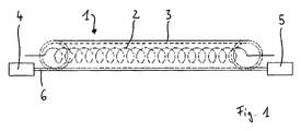
- an infrared radiator heat source 1 is shown schematically, which has a device according to the invention.
- the infrared radiator heat source 1 is formed in this example of an incandescent filament 2 and a surrounding, cylindrical glass protective tube 3 made of quartz glass, which is open at both ends.
- a light source 4 for example a laser, is provided which generates an analysis light beam 6.
- This is, for example, coupled by means of a focusing optics or a light guide to an end face of the glass protective tube 3 in the material.
- the analysis light beam 6 exits the glass protective tube 3 and falls into the detector 5 arranged there. There, the analysis light beam is analyzed and a breakage of the glass protective tube 3 is detected when a deviation from a calibration has been established. Then a corresponding signal can be output.
- the infrared radiator heat source 1 shown there two filaments 2 are arranged in parallel in a glass protective tube 3, in which two parallel receiving spaces are formed.
- the light source 4 and the detector 5 are located at one end of the glass protective tube 3.
- the analysis light beam 6 is introduced into the front side of the material of the glass protective tube 3, exits at the opposite end again and is in the area 7 by suitable means (mirror, optical fiber , Prisms or the like) deflected, so that it enters at another point and in the opposite direction again in the material of the glass protective tube 3 and this passes through again.
- suitable means mirror, optical fiber , Prisms or the like
- light source 4 and detector 5 can be arranged on one side of the glass tube 3, which can save space and with regard to the supply of operating voltage and signal lines can be beneficial.
- the infrared radiator heat source 1 shown in Fig. 3 includes three in parallel arrangement each surrounded by its own glass protective tube 3 filaments 2.
- the analysis light 6 generated by the light source 4 is successively passed through the three glass protective tubes 3 in the longitudinal direction before it at the end of the third Glass protective tube 3 meets the detector 5.
- the analysis light 6 is deflected as explained above for FIG. 2 in each case.
- This embodiment allows the same review several glass protection tubes 3 by their optical series connection.
- the number of consecutive ones Glass tubes 3 is not limited to three, but in principle arbitrary. A limit is set only by the absorption in the glass, since this must not be too high for a reliable analysis.
Landscapes
- Physics & Mathematics (AREA)
- General Physics & Mathematics (AREA)
- Analytical Chemistry (AREA)
- Health & Medical Sciences (AREA)
- Life Sciences & Earth Sciences (AREA)
- Chemical & Material Sciences (AREA)
- Biochemistry (AREA)
- General Health & Medical Sciences (AREA)
- Immunology (AREA)
- Pathology (AREA)
- Spectroscopy & Molecular Physics (AREA)
- Investigating Or Analysing Materials By Optical Means (AREA)
- Investigating Materials By The Use Of Optical Means Adapted For Particular Applications (AREA)
- Investigating Or Analyzing Materials Using Thermal Means (AREA)
Description
- Die Erfindung betrifft ein Verfahren gemäß dem Oberbegriff des Anspruchs 1.
- In technischen Erwärmungsverfahren wird auf den verschiedensten Gebieten häufig mittelwellige Infrarotstrahlung eingesetzt, um Prozeßwärme einzuspeisen. Als Wärmequellen dienen dabei häufig mittelwellige Strahlungsquellen, wie Glühdrahtwendeln, die von einem klaren, für Infrarotstrahlung durchlässigen Glasschutzrohr bzw. mehreren solcher Rohre umgeben sind. Diese Rohre sind stirnseitig offen, da es nicht erforderlich ist, die Glühwendel gegen die Umgebungsluft abzuschirmen - diese können im mittelwelligen Infrarot-Bereich an Luft stabil über mehrere Jahre oxidationsfrei betrieben werden. Das Glasschutzrohr wird vielmehr primär für den elektrischen Schutz benötigt.
- Da die Umgebungsluft im wesentlichen ohne Einfluß auf die Glühwendel ist, führt ein Bruch des Glasschutzrohres anders als beispielsweise ein Bruch des Glaskolbens bei einer herkömmlichen Glühlampe nicht zwangsweise zu einer Veränderung des elektrischen Verhaltens der Infrarotstrahlerwärmequelle. Somit besteht die Gefahr, daß ein derartiger Bruch unbemerkt bleibt.
- Abgesehen davon, daß bei gebrochenem Glasschutzrohr die elektrische Isolierung nicht mehr sicher gegeben ist, ist es bei der Anwendung dieser Infrarotstrahlerwärmequellen in empfindlichen Prozessen erforderlich, eine Verschmutzung des Bestrahlungsgutes mit Glasbruchstücken zu verhindern oder den Prozeß bei einem Glasbruch umgehend zu stoppen, damit alle Teile, die mit Glasbruchstücken in Verbindung gekommen sein können, ausgesondert werden können und eine Verschmutzung weiteren Prozeßgutes unterbleibt.
- In der US 3,533,704 sind ein Verfahren und eine Vorrichtung offenbart, bei denen mit Hilfe von Licht Glasgegenstände, bspw. Glasrohre, in einer Art Qualitätskontrolle nach der Herstellung auf Brüche getestet werden. Dazu wird Licht frontal in den Glasgegenstand eingeleitet und mit einem Detektor das aus dem Glas austretende Licht untersucht. Intensitätsschwankungen zeigen einen Bruch an.
- In der US 3,777,171 werden ein ähnliches Verfahren und eine vergleichbare Vorrichtung angegeben, die der Detektion von Einschlüssen bzw. Inhomogenitäten in Glasgegenständen, bspw. Glasrohren, dienen.
- Die in den beiden genannten Druckschriften genannten Verfahren und Vorrichtungen dienen der Qualitätskontrolle und sind nicht für den Einsatz zur Überwachung eines Glasschutzrohres während des Betriebes einer Infrarotstrahlerwärmequelle oder eine andere insitu Überwachung vorgesehen.
- Vor diesem Hintergrund ist es Aufgabe der Erfindung, ein Verfahren und eine Einrichtung zu schaffen, mit dem bzw. mit der ein Glasschutzrohr für eine Glühwendel einer Infrarotstrahlerwärmequelle während des Betriebes zuverlässig auf Unversehrtheit überprüft und ein Bruch desselben sicher festgestellt werden kann.
- Zur Lösung dieser Aufgabe wird mit der Erfindung ein Verfahren gemäß Anspruch 1 bzw. eine Einrichtung nach Anspruch 6 vorgeschlagen.
- Vorteilhafte Ausgestaltungen des Verfahrens sind in den Ansprüchen 2 bis 5, Weiterbildungen der Vorrichtung sind in den Ansprüchen 7 bis 10 angegeben.
- Die Erfindung baut auf der Erkenntnis auf, daß ein Bruch eine Veränderung der optischen Eigenschaften des Glasschutzrohres bedingt. Es verändert sich durch Bruchkanten in dem Material die Lichtleitfähigkeit des Materials (an derartigen Bruchkanten kommt es zu Teil- bzw. sogar Totalreflektionen) und es können Interferenzphänomene auftreten, die eine Veränderung der Phase des Lichtes sowie der Intensität hervorrufen können. Bisweilen kann man Veränderungen der optischen Eigenschaften des Glases, insbesondere des Quarzglases, bereits vor einem sichtbaren Bruch feststellen, wenn das Material auf kristalliner Ebene bereits Veränderungen erfahren hat.
- Diese Tatsache wird dadurch ausgenutzt, daß Analyselicht in das Material des Glasschutzrohres eingekoppelt und durch das Material durchgeleitet wird. Am Ende des Materials wird das Analyselicht detektiert und analysiert, bspw. hinsichtlich der Intensität, der Phase oder der Wellenlänge. Bei intaktem Glasschutzrohr wird dann eine Eichung vorgenommen, d.h. die Analysewerte bei intaktem Glasschutzrohr werden bestimmt und als Richtwerte für ein intaktes Glasschutzrohr behandelt. Kommt es im Betrieb der Infrarotstrahlerwärmequelle dann zu Abweichungen dieser Analysewerte in einem vorbestimmten, außerhalb einer Toleranzgrenze liegenden Umfang, kann auf einen Glasbruch geschlossen werden.
- Dabei ist vorgesehen, das Analyselicht von einer Stirnseite des Glasschutzrohres her in dessen Längsrichtung zu der gegenüberliegenden Stirnseite zu leiten. Auf diese Weise kann mit einem einzigen Lichtdurchtritt ein vergleichsweise großer Abschnitt des Glasschutzrohres auf Unversehrtheit überprüft bzw. überwacht werden.
- Da Glasschutzrohre im intakten Zustand sich im wesentlichen wie ein optischer Leiter verhalten und nahezu keinen Strahlungsverlust haben, ist es möglich, den Strahl entweder mittels Mitteln zum Umlenken, wie z. B. Reflektoren, gebogenen Lichtleitfasern oder ähnlichem, umzulenken und dasselbe Glasschutzrohr an anderer Stelle erneut in entgegen gesetzter Richtung durchlaufen zu lassen oder mehrere Glasschutzrohre gleichermaßen optisch in Reihe geschaltet hintereinander durchlaufen zu lassen, ehe eine Detektion und Analyse erfolgt. Hierfür weist die erfindungsgemäße Einrichtung neben einer Lichtquelle, Mitteln zum Einleiten des Analyselichtstrahls in das Material des Glasschutzrohres, einem Detektor sowie Mitteln zum Analysieren des Analyselichtstrahls Mittel zum Umlenken des aus einer Stirnseite des Glasschutzrohres zum ortsversetzt entgegen gesetzten Wiedereintritt in dieselbe Stirnseite des Glasschutzrohres bzw. zum Einleiten des Analyselichtstrahles in eine Stirnseite eines weiteren Glasschutzrohres parallel zu dessen Längsrichtung auf und der Detektor ist an der Stirnseite eines Glasschutzrohres angeordnet, aus der der Analyselichtstrahl als letztes austritt.
- Als Analyselichtstrahl wird ein Laserlichtstrahl bevorzugt, da Laserlicht zum einen mit guter Reproduzierbarkeit erzeugt werden kann, so daß eine einmal vorgenommene Eichung beibehalten werden kann, und da ein Laserlichtstrahl sehr gut gebündelt ist, er nahezu kein Streulicht erzeugt. Letzteres bedingt, daß der Strahl einfach vollständig in das Material eingebracht werden kann und bei intaktem Glasschutzrohr auch kein Licht abseits des vorgesehenen Lichtweges austritt und damit das Analyseergebnis beeinträchtigt.
- Um Schwankungen in der Lichtquelle auszugleichen und nicht auf eine einmal vorgenommene Eichung zurückgreifen zu müssen, kann von dem Analyselichtstrahl ein Referenzlichtstrahl abgespalten werden, der ohne das Glasschutzrohr zu durchlaufen detektiert und analysiert und mit dem aus dem Glasschutzrohr austretenden Analyselichtstrahl verglichen wird. Bei zuvor bestimmten und festgelegten Abweichungen kann dann ein Bruch des Glasschutzrohres angezeigt werden. Das Aufteilen des Lichtstrahles kann bspw. mittels eines halbdurchlässigen Spiegels als Strahlteiler erfolgen.
- Das erfindungsgemäße Verfahren bzw. die Einrichtung kann bei festgestelltem Bruch bspw. einen Alarm auslösen und den Produktionsprozeß automatisch anhalten.
- Nachfolgend wird die Erfindung in anhand der beigefügten Figuren geschilderten Ausführungsbeispielen näher erläutert. Aus dieser Beschreibung lassen sich weitere Vorteile und Merkmale der Erfindung erkennen. In den Figuren zeigen:
- Fig. 1
- ein erstes Ausführungsbeispiel einer erfindungsgemäßen Einrichtung zur Überprüfung eines Glasschutzrohres auf Unversehrtheit,
- Fig. 2
- ein zweites Ausführungsbeispiel einer erfindungsgemäßen Einrichtung zur Überprüfung eines Glasschutzrohres auf Unversehrtheit und
- Fig. 3
- ein Ausführungsbeispiel einer erfindungsgemäßen Einrichtung zur Überprüfung mehrerer Glasschutzrohre auf Unversehrtheit.
- In Fig. 1 ist schematisch eine Infrarotstrahlerwärmequelle 1 gezeigt, welche eine erfindungsgemäße Einrichtung aufweist. Die Infrarotstrahlerwärmequelle 1 ist in diesem Beispiel aus einer Glühwendel 2 und einem dieses umgebenden, zylinderförmigen Glasschutzrohr 3 aus Quarzglas gebildet, welches an beiden Stirnseiten offen ist.
- Um das Glasschutzrohr 3 auf Unversehrtheit zu überprüfen, ist eine Lichtquelle 4, bspw. ein Laser, vorgesehen, die einen Analyselichtstrahl 6 erzeugt. Dieser wird bspw. mit Hilfe einer Fokussieroptik oder eines Lichtleiters an eine Stirnseite des Glasschutzrohres 3 in dessen Material eingekoppelt.
- An der gegenüberliegenden Stirnseite tritt der Analyselichtstrahl 6 aus dem Glasschutzrohr 3 aus und fällt in den dort angeordneten Detektor 5. Dort wird der Analyselichtstrahl analysiert und bei festgestellter Abweichung von einer vorgenommenen Eichung ein Bruch des Glasschutzrohres 3 festgestellt. Dann kann ein entsprechendes Signal ausgegeben werden.
- In Fig. 2 ist ein ähnliches Ausführungsbeispiel gezeigt. In der dort dargestellten Infrarotstrahlerwärmequelle 1 sind in einem Glasschutzrohr 3, in dem zwei parallele Aufnahmeräume ausgebildet sind, zwei Glühwendeln 2 parallel angeordnet. In diesem Beispiel liegen die Lichtquelle 4 und der Detektor 5 an einer Stirnseite des Glasschutzrohres 3. Der Analyselichtstrahl 6 wird stirnseitig in das Material des Glasschutzrohres 3 eingeleitet, tritt an der gegenüberliegenden Stirnseite wieder aus und wird im Bereich 7 mit geeigneten Mitteln (Spiegel, Lichtleitfaser, Prismen oder ähnlichem) umgelenkt, so daß es an anderer Stelle und in entgegen gesetzter Richtung wieder in das Material des Glasschutzrohres 3 eintritt und dieses erneut durchläuft. Auf diese Weise wird das Glasschutzrohr 3 entlang zweier Wege auf Unversehrtheit geprüft, und damit noch genauer. Zudem können Lichtquelle 4 und Detektor 5 auf einer Seite des Glasrohres 3 angeordnet werden, was Platz sparen kann und hinsichtlich der Versorgung mit Betriebsspannung sowie Signalleitungen von Vorteil sein kann.
- Die in Fig. 3 gezeigte Infrarotstrahlerwärmequelle 1 enthält in paralleler Anordnung drei jeweils von einem eigenen Glasschutzrohr 3 umgebene Glühwendeln 2. Hier wird das von der Lichtquelle 4 erzeugte Analyselicht 6 nacheinander durch die drei Glasschutzrohre 3 in deren Längsrichtung durchgeleitet, ehe es am Ende des dritten Glasschutzrohrs 3 auf den Detektor 5 trifft. In den Bereichen 7 wird das Analyselicht 6 wie oben zu Fig. 2 erläutert jeweils umgelenkt.
- Diese Ausführungsvariante erlaubt die Überprüfung gleich mehrerer Glasschutzrohre 3 durch deren optische Hintereinanderschaltung. Die Anzahl der so hintereinander geschalteten Glasrohre 3 ist dabei nicht auf drei beschränkt, sondern prinzipiell beliebig. Eine Grenze wird lediglich durch die Absorption in dem Glas gesetzt, da diese für eine zuverlässige Analyse nicht zu hoch sein darf.
-
- 1
- Infrarotstrahlerwärmequelle
- 2
- Glühwendel
- 3
- Glasschutzrohr
- 4
- Lichtquelle
- 5
- Detektor
- 6
- Analyselichtstrahl
- 7
- Bereich
Claims (10)
- Verfahren zum Überprüfen eines Glasschutzrohres, insbesondere aus Quarzglas, für die Glühwendel einer Infrarotstrahlerwärmequelle auf Unversehrtheit, wobei ein Analyselichtstrahl in das Material des Glasschutzrohres ein- und durch dieses hindurchgeleitet wird und wobei der aus dem Glasschutzrohr austretende Analyselichtstrahl detektiert und hinsichtlich Intensität und/oder Wellenlänge und/oder Phase analysiert wird und wobei anhand der Analyse festgestellt wird, ob das Glasschutzrohr beschädigt oder unversehrt ist, dadurch gekennzeichnet, daß der Analyselichtstrahl stirnseitig in das Material des Glasschutzrohres ein- und in Längsrichtung durch dieses hindurchgeleitet wird.
- Verfahren nach Anspruch 1, dadurch gekennzeichnet, daß der Analyselichtstrahl an einer ersten Stirnseite des Glasschutzrohres in das Material des Glasschutzrohres eingeleitet, an der gegenüber liegenden, zweiten Stirnseite des Glasschutzrohres zu einem weiteren Durchtritt durch das Glasschutzrohr an anderer Stelle und in entgegen gesetzter Richtung umgelenkt bzw. reflektiert und anschließend an der Stirnseite des Glasschutzrohres, an der er zunächst in das Material eingeleitet worden ist, detektiert und analysiert wird.
- Verfahren nach einem der vorhergehenden Ansprüche, dadurch gekennzeichnet, daß der Analyselichtstrahl nacheinander jeweils in Längsrichtung durch mehrere Glasschutzrohre geleitet wird und erst nach Durchlaufen des letzten Glasschutzrohres detektiert und analysiert wird.
- Verfahren nach einem der vorhergehenden Ansprüche, dadurch gekennzeichnet, daß der Analyselichtstrahl vor dem ersten Einleiten in eine Stirnseite eines Glasschutzrohres geteilt und so ein Referenzlichtstrahl abgespalten wird und daß der Referenzlichtstrahl ohne Durchleitung durch die Glasschutzrohre zum Vergleich zusammen mit dem aus dem Glasschutzrohr austretenden Analyselichtstrahl detektiert und analysiert wird.
- Verfahren nach einem der vorhergehenden Ansprüche, dadurch gekennzeichnet, daß als Analyselicht Laserlicht verwendet wird.
- Einrichtung zum Überprüfen eines Glasschutzrohres (3), insbesondere aus Quarzglas, für die Glühwendel (2) einer Infrarotstrahlerwärmequelle (1) auf Unversehrtheit mit: einer Lichtquelle (4) zum Erzeugen eines Analyselichtstrahls (6),
Mitteln zum Einleiten des Analyselichtstrahls (6) in das Material des Glasschutzrohres (3),
einem Detektor (5) zum Detektieren des aus dem Glasschutzrohr (3) austretenden Analyselichtstrahls (6) und Mitteln zum Analysieren des Analyselichtstrahls (6) hinsichtlich Intensität und/oder Wellenlänge und/oder Phase, dadurch gekennzeichnet, daß die Mittel zum Einleiten des Analyselichtstrahls (6) zum Einleiten des Analyselichtstrahls (6) an einer Stirnseite des Glasschutzrohres (3) parallel zu dessen Längsrichtung einrichtbar sind. - Einrichtung nach Anspruch 6, dadurch gekennzeichnet, daß diese Mittel zum Umlenken des aus einer Stirnseite des Glasschutzrohres (3) zum ortsversetzt entgegen gesetzten Wiedereintritt in dieselbe Stirnseite des Glasschutzrohres (3) bzw. zum Einleiten des Analyselichtstrahles (6) in eine Stirnseite eines weiteren Glasschutzrohres (3) parallel zu dessen Längsrichtung aufweisen und daß der Detektor (5) an der Stirnseite eines Glasschutzrohres (3) angeordnet ist, aus der der Analyselichtstrahl (6) als letztes austritt.
- Einrichtung nach Anspruch 7, dadurch gekennzeichnet, daß die Mittel zum Umlenken des Analyselichtstrahles (6) eine Lichtleitfaser, einen Reflektor und/oder ein Prisma umfassen.
- Einrichtung nach einem der Ansprüche 6 bis 8, dadurch gekennzeichnet, daß sie zwischen der Lichtquelle (4) und der Stirnseite des Glasschutzrohres (3), in die der Analyselichtstrahl (6) zuerst eintritt, einen Strahlteiler zum Erzeugen eines Referenzlichtstrahles aufweist, wobei Mittel vorgesehen sind, den Referenzlichtstrahl zu dem Detektor (5) zu leiten.
- Einrichtung nach einem der Ansprüche 6 bis 9, dadurch gekennzeichnet, daß die Lichtquelle (4) eine LaserLichtquelle ist.
Priority Applications (4)
| Application Number | Priority Date | Filing Date | Title |
|---|---|---|---|
| DE502004001661T DE502004001661D1 (de) | 2004-01-07 | 2004-01-07 | Verfahren und Einrichtung zum Überprüfen eines Glasschutzrohres für die Glühwendel einer Infrarotstrahlerwärmequelle auf Unversertheit |
| AT04000117T ATE341760T1 (de) | 2004-01-07 | 2004-01-07 | Verfahren und einrichtung zum überprüfen eines glasschutzrohres für die glühwendel einer infrarotstrahlerwärmequelle auf unversertheit |
| EP04000117A EP1553403B1 (de) | 2004-01-07 | 2004-01-07 | Verfahren und Einrichtung zum Überprüfen eines Glasschutzrohres für die Glühwendel einer Infrarotstrahlerwärmequelle auf Unversertheit |
| US11/428,651 US7349081B2 (en) | 2004-01-07 | 2006-07-05 | Method and device for checking the integrity of a glass protecting tube for the spiral-wound filament of an infrared radiator heat source |
Applications Claiming Priority (1)
| Application Number | Priority Date | Filing Date | Title |
|---|---|---|---|
| EP04000117A EP1553403B1 (de) | 2004-01-07 | 2004-01-07 | Verfahren und Einrichtung zum Überprüfen eines Glasschutzrohres für die Glühwendel einer Infrarotstrahlerwärmequelle auf Unversertheit |
Publications (2)
| Publication Number | Publication Date |
|---|---|
| EP1553403A1 EP1553403A1 (de) | 2005-07-13 |
| EP1553403B1 true EP1553403B1 (de) | 2006-10-04 |
Family
ID=34585942
Family Applications (1)
| Application Number | Title | Priority Date | Filing Date |
|---|---|---|---|
| EP04000117A Expired - Lifetime EP1553403B1 (de) | 2004-01-07 | 2004-01-07 | Verfahren und Einrichtung zum Überprüfen eines Glasschutzrohres für die Glühwendel einer Infrarotstrahlerwärmequelle auf Unversertheit |
Country Status (4)
| Country | Link |
|---|---|
| US (1) | US7349081B2 (de) |
| EP (1) | EP1553403B1 (de) |
| AT (1) | ATE341760T1 (de) |
| DE (1) | DE502004001661D1 (de) |
Families Citing this family (4)
| Publication number | Priority date | Publication date | Assignee | Title |
|---|---|---|---|---|
| EP1553403B1 (de) | 2004-01-07 | 2006-10-04 | Volker Dipl.-Ing. Schaft | Verfahren und Einrichtung zum Überprüfen eines Glasschutzrohres für die Glühwendel einer Infrarotstrahlerwärmequelle auf Unversertheit |
| CN102082054B (zh) * | 2010-12-23 | 2012-03-21 | 湖州太箭照明有限公司 | 一种多螺旋灯丝的检验方法 |
| US20130250288A1 (en) * | 2012-03-22 | 2013-09-26 | Shenzhen China Star Optoelectronics Technology Co., Ltd. | Glass substrate inspection device and inspection method thereof |
| CN112125506A (zh) * | 2020-09-23 | 2020-12-25 | 苏州大学 | 螺旋相位调制片的制备方法及其产生涡旋光束的方法 |
Family Cites Families (6)
| Publication number | Priority date | Publication date | Assignee | Title |
|---|---|---|---|---|
| CH465269A (de) * | 1967-06-15 | 1968-11-15 | Emhart Zuerich Sa | Einrichtung zur optischen Prüfung von gläsernen Gegenständen auf Risse |
| US3777171A (en) * | 1971-07-26 | 1973-12-04 | Westinghouse Electric Corp | Method and apparatus for detecting flaws in continuous length tubular glass |
| FR2500630A1 (fr) * | 1981-02-25 | 1982-08-27 | Leser Jacques | Procede pour la recherche des defauts des feuilles de verre et dispositif mettant en oeuvre ce procede |
| US4483615A (en) * | 1981-12-18 | 1984-11-20 | Owens-Illinois, Inc. | Method and apparatus for detecting checks in glass tubes |
| KR20030046616A (ko) * | 2001-12-06 | 2003-06-18 | 삼성전자주식회사 | 레이져 광 산란을 이용한 고순도 글래스 튜브의 미세 기포분석 장치 |
| EP1553403B1 (de) | 2004-01-07 | 2006-10-04 | Volker Dipl.-Ing. Schaft | Verfahren und Einrichtung zum Überprüfen eines Glasschutzrohres für die Glühwendel einer Infrarotstrahlerwärmequelle auf Unversertheit |
-
2004
- 2004-01-07 EP EP04000117A patent/EP1553403B1/de not_active Expired - Lifetime
- 2004-01-07 AT AT04000117T patent/ATE341760T1/de not_active IP Right Cessation
- 2004-01-07 DE DE502004001661T patent/DE502004001661D1/de not_active Expired - Lifetime
-
2006
- 2006-07-05 US US11/428,651 patent/US7349081B2/en not_active Expired - Fee Related
Also Published As
| Publication number | Publication date |
|---|---|
| US7349081B2 (en) | 2008-03-25 |
| EP1553403A1 (de) | 2005-07-13 |
| DE502004001661D1 (de) | 2006-11-16 |
| US20060274307A1 (en) | 2006-12-07 |
| ATE341760T1 (de) | 2006-10-15 |
Similar Documents
| Publication | Publication Date | Title |
|---|---|---|
| DE10243449B4 (de) | CARS-Mikroskop und Verfahren zur CARS-Mikroskopie | |
| DE3220785C2 (de) | Vorrichtung zur kontinuierlichen Messung des Anteils der kondensierten Phase in einem Dampfstrom | |
| DE3031589C2 (de) | Vorrichtung zur Schadensfeststellung in einer Lichtleitfaser zur Übertragung von Laserleistung | |
| DE10115589B4 (de) | Konfokales Scanmikroskop | |
| DE3918618C2 (de) | ||
| EP1164406A2 (de) | Verfahren und Vorrichtung zur Beleuchtung eines Objekts | |
| DE2832847A1 (de) | Kontroll- und sicherheitseinrichtung fuer ein laser-medizinisches geraet | |
| DE3910438A1 (de) | Verfahren und vorrichtung zur polymerisation eines koerpers aus dentalkunststoff | |
| WO2005030433A1 (de) | Vorrichtung und verfahren zur überwachung eines schutzglases einer laseroptik auf bruch und/oder verschmutzung | |
| DE3205507A1 (de) | Vorrichtung zum messen der von einem chirurgischen lasergeraet abgegebenen laserlichtenergie | |
| EP1553403B1 (de) | Verfahren und Einrichtung zum Überprüfen eines Glasschutzrohres für die Glühwendel einer Infrarotstrahlerwärmequelle auf Unversertheit | |
| DE4032967A1 (de) | Verfahren und vorrichtung zur ueberwachung von faserlichtleitern | |
| EP0450256A1 (de) | Lichtleiter-Sonde | |
| DE10031414B4 (de) | Vorrichtung zur Vereinigung optischer Strahlung | |
| DE102009052762B4 (de) | Laserbearbeitungskopf und Verfahren zur Vermeidung einer Beschädigung eines Lichtleitfaserendes | |
| DE4424961C2 (de) | Wählvorrichtung für ein photometrisches Instrument mit Lichtleitfasern zur Analyse von entfernt befindlichen Proben | |
| DE19840346C2 (de) | Verfahren und Einrichtung zur Diagnose und Überwachung der Übertragungsgüte eines faseroptischen Systems | |
| EP1182425A1 (de) | Materialprüfvorrichtung und deren Verwendung | |
| DE102019106954B4 (de) | Selbstnivellierender piercing-sensor in einer lichtleitkabelsteckverbindung | |
| DE2534023C2 (de) | Verfahren zum Feststellen von Fehlern in gesägtem oder gehobeltem Holz und Vorrichtung zur Durchführung des Verfahrens | |
| DE4226203A1 (de) | Verfahren zum Erkennen der Verschmutzung einer blanken Lichtleitfaser und Vorrichtung zu dessen Durchführung | |
| EP1156310A1 (de) | Optisches Referenzelement und Verfahren zur spektralen Kalibrierung eines optischen Spektrumanalysators | |
| DE19716228C2 (de) | Vorrichtung und Verfahren zur Überprüfung einer Oberfläche einer optischen Komponente | |
| DE2709214A1 (de) | Anordnung fuer die laser-spektralanalyse | |
| AT522216A1 (de) | Analysieren von Gas mittels Raman-Spektroskopie |
Legal Events
| Date | Code | Title | Description |
|---|---|---|---|
| PUAI | Public reference made under article 153(3) epc to a published international application that has entered the european phase |
Free format text: ORIGINAL CODE: 0009012 |
|
| 17P | Request for examination filed |
Effective date: 20040623 |
|
| AK | Designated contracting states |
Kind code of ref document: A1 Designated state(s): AT BE BG CH CY CZ DE DK EE ES FI FR GB GR HU IE IT LI LU MC NL PT RO SE SI SK TR |
|
| AX | Request for extension of the european patent |
Extension state: AL LT LV MK |
|
| AKX | Designation fees paid |
Designated state(s): AT BE BG CH CY CZ DE DK EE ES FI FR GB GR HU IE IT LI LU MC NL PT RO SE SI SK TR |
|
| GRAP | Despatch of communication of intention to grant a patent |
Free format text: ORIGINAL CODE: EPIDOSNIGR1 |
|
| GRAS | Grant fee paid |
Free format text: ORIGINAL CODE: EPIDOSNIGR3 |
|
| GRAA | (expected) grant |
Free format text: ORIGINAL CODE: 0009210 |
|
| AK | Designated contracting states |
Kind code of ref document: B1 Designated state(s): AT BE BG CH CY CZ DE DK EE ES FI FR GB GR HU IE IT LI LU MC NL PT RO SE SI SK TR |
|
| PG25 | Lapsed in a contracting state [announced via postgrant information from national office to epo] |
Ref country code: IT Free format text: LAPSE BECAUSE OF FAILURE TO SUBMIT A TRANSLATION OF THE DESCRIPTION OR TO PAY THE FEE WITHIN THE PRESCRIBED TIME-LIMIT;WARNING: LAPSES OF ITALIAN PATENTS WITH EFFECTIVE DATE BEFORE 2007 MAY HAVE OCCURRED AT ANY TIME BEFORE 2007. THE CORRECT EFFECTIVE DATE MAY BE DIFFERENT FROM THE ONE RECORDED. Effective date: 20061004 Ref country code: NL Free format text: LAPSE BECAUSE OF FAILURE TO SUBMIT A TRANSLATION OF THE DESCRIPTION OR TO PAY THE FEE WITHIN THE PRESCRIBED TIME-LIMIT Effective date: 20061004 Ref country code: SI Free format text: LAPSE BECAUSE OF FAILURE TO SUBMIT A TRANSLATION OF THE DESCRIPTION OR TO PAY THE FEE WITHIN THE PRESCRIBED TIME-LIMIT Effective date: 20061004 Ref country code: SK Free format text: LAPSE BECAUSE OF FAILURE TO SUBMIT A TRANSLATION OF THE DESCRIPTION OR TO PAY THE FEE WITHIN THE PRESCRIBED TIME-LIMIT Effective date: 20061004 Ref country code: CZ Free format text: LAPSE BECAUSE OF FAILURE TO SUBMIT A TRANSLATION OF THE DESCRIPTION OR TO PAY THE FEE WITHIN THE PRESCRIBED TIME-LIMIT Effective date: 20061004 Ref country code: FI Free format text: LAPSE BECAUSE OF FAILURE TO SUBMIT A TRANSLATION OF THE DESCRIPTION OR TO PAY THE FEE WITHIN THE PRESCRIBED TIME-LIMIT Effective date: 20061004 Ref country code: RO Free format text: LAPSE BECAUSE OF FAILURE TO SUBMIT A TRANSLATION OF THE DESCRIPTION OR TO PAY THE FEE WITHIN THE PRESCRIBED TIME-LIMIT Effective date: 20061004 Ref country code: IE Free format text: LAPSE BECAUSE OF FAILURE TO SUBMIT A TRANSLATION OF THE DESCRIPTION OR TO PAY THE FEE WITHIN THE PRESCRIBED TIME-LIMIT Effective date: 20061004 |
|
| REG | Reference to a national code |
Ref country code: GB Ref legal event code: FG4D Free format text: NOT ENGLISH |
|
| REG | Reference to a national code |
Ref country code: CH Ref legal event code: EP |
|
| REG | Reference to a national code |
Ref country code: IE Ref legal event code: FG4D Free format text: LANGUAGE OF EP DOCUMENT: GERMAN |
|
| REF | Corresponds to: |
Ref document number: 502004001661 Country of ref document: DE Date of ref document: 20061116 Kind code of ref document: P |
|
| PG25 | Lapsed in a contracting state [announced via postgrant information from national office to epo] |
Ref country code: DK Free format text: LAPSE BECAUSE OF FAILURE TO SUBMIT A TRANSLATION OF THE DESCRIPTION OR TO PAY THE FEE WITHIN THE PRESCRIBED TIME-LIMIT Effective date: 20070104 Ref country code: BG Free format text: LAPSE BECAUSE OF FAILURE TO SUBMIT A TRANSLATION OF THE DESCRIPTION OR TO PAY THE FEE WITHIN THE PRESCRIBED TIME-LIMIT Effective date: 20070104 Ref country code: SE Free format text: LAPSE BECAUSE OF FAILURE TO SUBMIT A TRANSLATION OF THE DESCRIPTION OR TO PAY THE FEE WITHIN THE PRESCRIBED TIME-LIMIT Effective date: 20070104 |
|
| PG25 | Lapsed in a contracting state [announced via postgrant information from national office to epo] |
Ref country code: ES Free format text: LAPSE BECAUSE OF FAILURE TO SUBMIT A TRANSLATION OF THE DESCRIPTION OR TO PAY THE FEE WITHIN THE PRESCRIBED TIME-LIMIT Effective date: 20070115 |
|
| GBT | Gb: translation of ep patent filed (gb section 77(6)(a)/1977) |
Effective date: 20070109 |
|
| PG25 | Lapsed in a contracting state [announced via postgrant information from national office to epo] |
Ref country code: MC Free format text: LAPSE BECAUSE OF NON-PAYMENT OF DUE FEES Effective date: 20070131 |
|
| PG25 | Lapsed in a contracting state [announced via postgrant information from national office to epo] |
Ref country code: PT Free format text: LAPSE BECAUSE OF FAILURE TO SUBMIT A TRANSLATION OF THE DESCRIPTION OR TO PAY THE FEE WITHIN THE PRESCRIBED TIME-LIMIT Effective date: 20070316 |
|
| NLV1 | Nl: lapsed or annulled due to failure to fulfill the requirements of art. 29p and 29m of the patents act | ||
| ET | Fr: translation filed | ||
| REG | Reference to a national code |
Ref country code: IE Ref legal event code: FD4D |
|
| PLBE | No opposition filed within time limit |
Free format text: ORIGINAL CODE: 0009261 |
|
| STAA | Information on the status of an ep patent application or granted ep patent |
Free format text: STATUS: NO OPPOSITION FILED WITHIN TIME LIMIT |
|
| 26N | No opposition filed |
Effective date: 20070705 |
|
| BERE | Be: lapsed |
Owner name: SCHAFT, VOLKER DIPL.-ING. Effective date: 20070131 |
|
| PG25 | Lapsed in a contracting state [announced via postgrant information from national office to epo] |
Ref country code: BE Free format text: LAPSE BECAUSE OF NON-PAYMENT OF DUE FEES Effective date: 20070131 |
|
| PG25 | Lapsed in a contracting state [announced via postgrant information from national office to epo] |
Ref country code: GR Free format text: LAPSE BECAUSE OF FAILURE TO SUBMIT A TRANSLATION OF THE DESCRIPTION OR TO PAY THE FEE WITHIN THE PRESCRIBED TIME-LIMIT Effective date: 20070105 |
|
| PG25 | Lapsed in a contracting state [announced via postgrant information from national office to epo] |
Ref country code: AT Free format text: LAPSE BECAUSE OF NON-PAYMENT OF DUE FEES Effective date: 20070107 |
|
| PG25 | Lapsed in a contracting state [announced via postgrant information from national office to epo] |
Ref country code: EE Free format text: LAPSE BECAUSE OF FAILURE TO SUBMIT A TRANSLATION OF THE DESCRIPTION OR TO PAY THE FEE WITHIN THE PRESCRIBED TIME-LIMIT Effective date: 20061004 |
|
| REG | Reference to a national code |
Ref country code: CH Ref legal event code: PL |
|
| PG25 | Lapsed in a contracting state [announced via postgrant information from national office to epo] |
Ref country code: LI Free format text: LAPSE BECAUSE OF NON-PAYMENT OF DUE FEES Effective date: 20080131 Ref country code: CH Free format text: LAPSE BECAUSE OF NON-PAYMENT OF DUE FEES Effective date: 20080131 |
|
| PG25 | Lapsed in a contracting state [announced via postgrant information from national office to epo] |
Ref country code: FR Free format text: LAPSE BECAUSE OF NON-PAYMENT OF DUE FEES Effective date: 20070131 |
|
| PG25 | Lapsed in a contracting state [announced via postgrant information from national office to epo] |
Ref country code: CY Free format text: LAPSE BECAUSE OF FAILURE TO SUBMIT A TRANSLATION OF THE DESCRIPTION OR TO PAY THE FEE WITHIN THE PRESCRIBED TIME-LIMIT Effective date: 20061004 Ref country code: LU Free format text: LAPSE BECAUSE OF NON-PAYMENT OF DUE FEES Effective date: 20070107 |
|
| PG25 | Lapsed in a contracting state [announced via postgrant information from national office to epo] |
Ref country code: TR Free format text: LAPSE BECAUSE OF FAILURE TO SUBMIT A TRANSLATION OF THE DESCRIPTION OR TO PAY THE FEE WITHIN THE PRESCRIBED TIME-LIMIT Effective date: 20061004 Ref country code: HU Free format text: LAPSE BECAUSE OF FAILURE TO SUBMIT A TRANSLATION OF THE DESCRIPTION OR TO PAY THE FEE WITHIN THE PRESCRIBED TIME-LIMIT Effective date: 20070405 |
|
| REG | Reference to a national code |
Ref country code: DE Ref legal event code: R409 Ref document number: 502004001661 Country of ref document: DE |
|
| REG | Reference to a national code |
Ref country code: DE Ref legal event code: R409 Ref document number: 502004001661 Country of ref document: DE |
|
| REG | Reference to a national code |
Ref country code: DE Ref legal event code: R119 Ref document number: 502004001661 Country of ref document: DE Effective date: 20110802 |
|
| PGFP | Annual fee paid to national office [announced via postgrant information from national office to epo] |
Ref country code: FR Payment date: 20120809 Year of fee payment: 9 |
|
| REG | Reference to a national code |
Ref country code: FR Ref legal event code: ST Effective date: 20130930 |
|
| PG25 | Lapsed in a contracting state [announced via postgrant information from national office to epo] |
Ref country code: FR Free format text: LAPSE BECAUSE OF NON-PAYMENT OF DUE FEES Effective date: 20130131 |
|
| PGFP | Annual fee paid to national office [announced via postgrant information from national office to epo] |
Ref country code: GB Payment date: 20150223 Year of fee payment: 12 |
|
| GBPC | Gb: european patent ceased through non-payment of renewal fee |
Effective date: 20160107 |
|
| PG25 | Lapsed in a contracting state [announced via postgrant information from national office to epo] |
Ref country code: GB Free format text: LAPSE BECAUSE OF NON-PAYMENT OF DUE FEES Effective date: 20160107 |
|
| PGFP | Annual fee paid to national office [announced via postgrant information from national office to epo] |
Ref country code: DE Payment date: 20170623 Year of fee payment: 14 |
|
| REG | Reference to a national code |
Ref country code: DE Ref legal event code: R119 Ref document number: 502004001661 Country of ref document: DE |
|
| PG25 | Lapsed in a contracting state [announced via postgrant information from national office to epo] |
Ref country code: DE Free format text: LAPSE BECAUSE OF NON-PAYMENT OF DUE FEES Effective date: 20180801 |