EP1553291A2 - Reciprocating piston engine - Google Patents
Reciprocating piston engine Download PDFInfo
- Publication number
- EP1553291A2 EP1553291A2 EP04405737A EP04405737A EP1553291A2 EP 1553291 A2 EP1553291 A2 EP 1553291A2 EP 04405737 A EP04405737 A EP 04405737A EP 04405737 A EP04405737 A EP 04405737A EP 1553291 A2 EP1553291 A2 EP 1553291A2
- Authority
- EP
- European Patent Office
- Prior art keywords
- piston
- control ring
- recess
- engine according
- pistons
- Prior art date
- Legal status (The legal status is an assumption and is not a legal conclusion. Google has not performed a legal analysis and makes no representation as to the accuracy of the status listed.)
- Granted
Links
Images
Classifications
-
- F—MECHANICAL ENGINEERING; LIGHTING; HEATING; WEAPONS; BLASTING
- F04—POSITIVE - DISPLACEMENT MACHINES FOR LIQUIDS; PUMPS FOR LIQUIDS OR ELASTIC FLUIDS
- F04B—POSITIVE-DISPLACEMENT MACHINES FOR LIQUIDS; PUMPS
- F04B1/00—Multi-cylinder machines or pumps characterised by number or arrangement of cylinders
- F04B1/04—Multi-cylinder machines or pumps characterised by number or arrangement of cylinders having cylinders in star- or fan-arrangement
- F04B1/053—Multi-cylinder machines or pumps characterised by number or arrangement of cylinders having cylinders in star- or fan-arrangement with actuating or actuated elements at the inner ends of the cylinders
Definitions
- the invention relates to a reciprocating engine with annular juxtaposed, radially directed piston-cylinder units and with an eccentric shaft extending through a the cylinder enclosing housing body of a machine housing extends and whose eccentric the Ausforcehub the Piston controls, with the inward stroke of the piston by a controlled common, engaging in the piston control ring becomes.
- a reciprocating piston engine whose pistons radially through an eccentric be moved outward, is known from EP 0088677.
- the outward stroke of the piston is through an eccentric and a rolling bearing enclosing this mechanically controlled during the inward stroke by the force a spring deformed by the lifting movement takes place, so that They the piston in contact with the outer ring of the bearing holds.
- Such a spring has u.a. the disadvantage that their arrangement the size of the machine adversely affected.
- For Their arrangement in the cylinder room also requires a room which acts as a dead space by an almost on the away stroke complete ejection of the medium is prevented.
- the Machine size mitbe carriedde size of the coupling ring results it thereby by its admission in a itself over the entire Scope of the cylinder block extending, even for his Assembly required large annular channel.
- This ring channel is used Also, the inclusion of a stop, a lateral ejection prevent the coupling ring from the annular groove of the piston should. Also by the relatively considerable size the dome ring, for which also a design made of wire provided is such a machine for high working speeds not suitable.
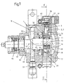
- the radial piston machine 1 has a preferably odd number For example, five piston-cylinder units 2,3, the ring-shaped next to each other, in a common, relatively flat Housing body 4 of a machine housing 5 is arranged are by in the massive material five radially directed, the piston 2 leading cylinder bores 3 incorporated are.
- the housing body 4 is corresponding The representation in Figure 2 preferably star-shaped and has on the outside five flange 6 for the tight assembly of Exhaust valves 7 and of a discharge line 8 enclosing Cylinder heads 9.
- the cylinder bores end 3 arranged in a centric to the eccentric shaft 12, smallest possible, circular gear chamber 10, in which the Eccentric 11 of the eccentric shaft 12 with a surrounding him Rolling 13 performs a circulation movement.
- the outer ring 14 of e.g. Rolling bearing designed as a needle bearing 13 is in constant contact with him, inner end face 15 of the piston 2, so that the circulation movement of the eccentric 11 the pistons 2 consecutive, pushes radially outwards to perform its outward stroke.
- This coupling causes the control ring 16 by the outward stroke of each piston 2 in order the orbital movement of the eccentric 11 is pulled outwards is and therefore arranged diametrically opposite one another Pulling the piston 2, pulls it inwards, so that it is hers Make an inward stroke.
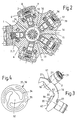
- the recess 17 of the piston has the shape of a toward a secant-guided and the cross-sectional shape of the control ring 16 adapted incision, thus parallel to each other Surfaces.
- the recess 17 from the inner End face 15 of the piston 2 a minimum distance, the thickness of a bottom wall 18 of the preferably as a hollow body executed piston 2 corresponds and she is on one limited peripheral region of the piston (2) as a lateral interruption its in cylinder 3 sliding, cylindrical sliding surface executed.
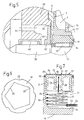
- five inner control surfaces 20 of the control ring 16 are at least approximately and go over a small, for better distribution of am Control ring 16 forces provided rounding 22 in the circumferentially following inner control surface 20 via, such that the control ring 16 has a polygonal inner contour Has.
- a slight convex curvature of these control surfaces 20 in the circumferential direction may be advantageous to a load the transversely to the piston axis end boundary edges 61.62 of the contact surfaces 18 counteract.
- the control ring 16 may extend across the pistons 2 and in this direction unhindered relative to the piston Transverse motion, which is characterized by the in-phase the orbital movement of the eccentric 11 taking place control movement results. In this case, slide his inner control surfaces 20 on the respective inner bottom wall 18 of the five pistons 2. In addition allow the laterally open recesses 17 of the piston. 2 when assembling the machine a simple assembly of the moving components.
- control ring 16 has five circular arc-shaped parts 21st a cylindrical surface, each through a recess 23 of the Control ring 16 are limited. These five recesses 23 form in each case an inflow opening to the through the recess 17th laterally open, cylindrical interior 24 of the piston. 2
- the recesses 23 are arranged such that they as shown in Fig.3 on a lateral Part of the respective engagement region of the control ring 16 extend, and the inflow into the piston recess 17th accordingly laterally and thereby tangentially in the cylindrical Interior 24 of the piston 2 takes place.
- the diaphragm 33 of a check valve 31 by means of its edge 35 e.g. by welding attached.
- the membrane 33 has a central locking part 32 and three extending from this arcuate to the membrane edge 35 Web portions 34, so that the web portions 34 spring elements form for the lifting movement of the closing part 32.
- connection blocks 39 From the cylindrical work chambers 3, the working medium flows in connection blocks 39, the connection via connecting channels 40 to a the machine housing 5 enclosing manifold 41 produce. Through this outside the housing body. 4 Attached terminal blocks are the plate-shaped parts of the Cylinder heads 9 under prestress close to the housing body. 4 held.
- the eccentric shaft 12 is in the machine housing 5 and its bell-shaped housing body 50 by two bearings 42,43 stored.
- a drive-side sealing arrangement 44 seals the Housing interior 45 axially outward, while the free, the eccentric 11 and a balance weight 46 supporting shaft end 47 in a housing space 48 ends, by a flanged Housing cover 49 is closed.
- a compensation channel through the eccentric shaft extend through.
- the inflow of the working medium in the reciprocating engine. 1 takes place via at least one bell-shaped second housing block 50 radially connected connection piece 51. Subsequently flows through it according to the illustration in 5 in the housing inner wall 52 provided axial channels 53,54 and encounters a rotating with the eccentric shaft 11 Baffle 55, at which a lubricant in the gaseous Operating medium is deposited. The flow continues by flow around the baffle plate 55 and a gap 56th between the baffle plate and the housing body 50 to the centric arranged to the housing and shaft axis 57 and circular Gear chamber 10 of the housing body 4, in which the eccentric 11 rotates so that the operating medium from the end Housing chamber 48 in the manner previously described in the piston 2 can flow.
- the reciprocating piston engine 1 is particularly suitable as a compressor of a CO 2 air conditioning system for installation in the engine compartment of a motor vehicle. Furthermore, the essential components of the invention of the machine are designed so that they can be produced in a simple manner and mounted to each other.
- the pistons 2 are made two telescopically nested parts and before her Association is at one of these parts, i. the piston bottom 29 having part, the valve diaphragm 33 attached and on the other part the recess 17 by a lateral milling produced.
- the piston bottom 29 having part, the valve diaphragm 33 attached and on the other part the recess 17 by a lateral milling produced.
- a reciprocating piston engine 1 according to the invention is for high rotational speeds of more than 10 000 rpm, so that the Balancing the eccentric shaft 12 and the rotating with it Components, i.a. by the balance weight 46 and e.g. a recess 60 on the co-rotating baffle plate 55 of is of particular importance.
Landscapes
- Engineering & Computer Science (AREA)
- Mechanical Engineering (AREA)
- General Engineering & Computer Science (AREA)
- Compressors, Vaccum Pumps And Other Relevant Systems (AREA)
- Reciprocating Pumps (AREA)
- Valve Device For Special Equipments (AREA)
- Lubrication Of Internal Combustion Engines (AREA)
- Details Of Reciprocating Pumps (AREA)
Abstract
Die Hubkolbenmaschine (1) hat ringförmig nebeneinander angeordnete,
radial gerichtete Kolben-Zylindereinheiten (2,3). Der
Auswärtshub der Kolben (2) wird durch den Exzenter (11) einer
gemeinsamen Exzenterwelle (12) gesteuert, während ihr Einwärtshub
durch einen Steuerring (16) gesteuert wird, der in
eine seitliche, in Richtung einer Sekante verlaufende, einer
Querschnittsform des Steuerringes (16) angepasste Aussparung
(17) jedes Kolbens (2) eingreift. Die Aussparung (17) wird
durch eine Bodenwand des Kolbens (2) begrenzt, mit der der
Steuerring (16) über eine innere Steuerfläche (20) in steuerndem
Gleitkontakt steht. Die Kolben (2) sind hohl ausgeführt
und tragen an ihrer Stirnseite die Membran eines Membranventils.
Die Hubkolbenmaschine (1) hat somit eine besonders kompakte
Bauweise und ist hoch belastbar, so dass sie sich besonders
als Kompressor einer CO2-Fahrzeugklimaanlage eignet.

Description
Die Erfindung betrifft eine Hubkolbenmaschine mit ringförmig nebeneinander angeordneten, radial gerichteten Kolben-Zylindereinheiten und mit einer Exzenterwelle , die sich durch einen die Zylinder einschließenden Gehäusekörper eines Maschinengehäuses erstreckt und deren Exzenter den Auswärtshub der Kolben steuert, wobei der Einwärtshub der Kolben durch einen gemeinsamen, in die Kolben eingreifenden Steuerring gesteuert wird.The invention relates to a reciprocating engine with annular juxtaposed, radially directed piston-cylinder units and with an eccentric shaft extending through a the cylinder enclosing housing body of a machine housing extends and whose eccentric the Auswärtshub the Piston controls, with the inward stroke of the piston by a controlled common, engaging in the piston control ring becomes.
Eine Hubkolbenmaschinen deren Kolben durch einen Exzenter radial auswärts bewegt werden, ist durch die EP 0088677 bekannt. Bei dieser wird nur der Auswärtshub der Kolben durch einen Exzenter und über ein diesen umschließendes Wälzlager mechanisch gesteuert, während der Einwärtshub durch die Kraft einer durch die Hubbewegung verformten Feder erfolgt, so dass sie den Kolben in Kontakt mit dem Außenring des Wälzlagers hält. Eine solche Feder hat u.a. den Nachteil, dass ihre Anordnung die Baugröße der Maschine nachteilig beeinflusst. Für Ihre Anordnung im Zylinderraum wird außerdem ein Raum benötigt, der als Totraum wirkt, indem beim Auswärtshub ein nahezu vollständiger Ausschub des Mediums verhindert wird.A reciprocating piston engine whose pistons radially through an eccentric be moved outward, is known from EP 0088677. In this only the outward stroke of the piston is through an eccentric and a rolling bearing enclosing this mechanically controlled during the inward stroke by the force a spring deformed by the lifting movement takes place, so that They the piston in contact with the outer ring of the bearing holds. Such a spring has u.a. the disadvantage that their arrangement the size of the machine adversely affected. For Their arrangement in the cylinder room also requires a room which acts as a dead space by an almost on the away stroke complete ejection of the medium is prevented.
Durch die GB 2225614 (JP2188678) ist es auch bekannt, die Rückholbewegung von jeweils zwei sich gegenüberliegenden, durch einen Exzenter nach aussen bewegten Kolben durch ein Paar von seitlichen Fortsätzen eines Kuppelringes auszuführen, die gabelförmig in eine Eindrehung eines inneren, sich in den Gehäuseraum hinein erstreckenden Kolbenendes mit Federvorspannung eingreifen. Folglich werden die Kolben nicht auf ihrer gesamten Länge in den zugehörigen Zylindern geführt und der für die Aufnahme des Kuppelringes und der aus den Zylindern herausragenden Kolbenenden benötigte Raum verhindert eine kompakte Bauweise der Maschine. Auch ist die Maschine aufgrund der federnd ausgeführten seitlichen Fortsätze des Kuppelringes nur als Pumpe mit verhältnismäßig niedriger Arbeitsgeschwindigkeit geeignet.It is also known from GB 2225614 (JP2188678) that Return movement of two opposite, by an eccentric outwardly moving piston by a Pair of lateral extensions of a coupling ring, the forked into a recess of an inner, in the housing space extending into the piston end with spring preload intervention. Consequently, the pistons are not on their guided total length in the associated cylinders and for receiving the coupling ring and the cylinders outstanding piston ends required space prevents one compact design of the machine. Also, the machine is due the resilient executed lateral extensions of the coupling ring only as a pump with a relatively low operating speed suitable.
Durch die AT 394892 ist es weiterhin bekannt, die Hubbewegung von ringförmig zueinander angeordneten Kolben allein durch einen Exzenter zu steuern, indem die Kolben über einen an ihrem radial inneren Ende vorgesehenen Kugelkopf in einen den Exzenter umschließenden, ringförmigen Steuerungskörper gelenkig eingreifen. Eine solche Kolbensteuerung hat für die Anordnung der mechanischen Kopplung zwischen dem den Exzenter umschließenden, z.B. ringförmigen Steuerungskörper und dem jeweiligen Kolben einen eine kompakte Bauweise verhindernden Raumbedarf, verbunden mit einer entsprechend aufwändigen Bauweise für die mechanische Kopplung mit dem Steuerungskörper.By AT 394892 it is also known, the lifting movement of annularly arranged piston only by a To control eccentric, by the pistons over one at their radially inner end provided ball in a the eccentric hinged, annular control body hinged intervention. Such a piston control has for the arrangement the mechanical coupling between the eccentric enclosing, e.g. annular control body and the respective Piston a compact design preventing Space requirement, combined with a correspondingly complex construction for the mechanical coupling with the control body.
Schließlich ist es durch die US 3259074 (DE 1453663) bekannt, für die Rückholbewegung von paarweise einander gegenüberliegenden Kolben einen gemeinsamen Kuppelring vorzusehen, der seitlich in eine umlaufende Nut der Kolben eingreift. Diese gemeinsame Kupplung von jeweils zwei gleichachsigen, einander gegenüberliegenden Kolbenpaaren durch nur einen Kuppelring wird durch einen seine Querverschiebung in dem zweiten Kolbenpaar zulassenden Eingriff über vier im Winkel von 90° zueinander angeordnete ebene Gleitflächen des Kuppelringes ermöglicht. Für ihren Kontakt mit dem Exzenter und den seitlichen Eingriff des Kuppelringes im mittleren Bereich der Kolbenlänge haben diese Kolben eine verhältnismäßig große Länge und die Maschine eine entsprechend große radiale Ausdehnung. Die die Maschinengröße mitbestimmende Größe des Kuppelringes ergibt sich dabei durch dessen Aufnahme in einem sich über den gesamten Umfang des Zylinderblocks erstreckenden, auch für seine Montage benötigten großen Ringkanal. Dieser Ringkanal dient auch der Aufnahme eines Anschlages, der ein seitliches Herausschleudern des Kuppelringes aus der Ringnut der Kolben verhindern soll. Auch durch die verhältnismäßig erhebliche Größe des Kuppelringes, für den auch eine Ausführung aus Draht vorgesehen ist, ist eine solche Maschine für hohe Arbeitsgeschwindigkeiten ungeeignet.Finally, it is known from US 3259074 (DE 1453663) for the return movement of pairs opposite each other Piston to provide a common coupling ring, the laterally engages in a circumferential groove of the piston. These common coupling of two equiaxed, each other opposite piston pairs by only one coupling ring is due to its transverse displacement in the second piston pair permitting engagement over four at an angle of 90 ° to each other arranged level sliding surfaces of the coupling ring allows. For their contact with the eccentric and the lateral Engagement of the coupling ring in the middle area of the piston length These pistons have a relatively large length and the Machine a correspondingly large radial extent. The the Machine size mitbestimmende size of the coupling ring results it thereby by its admission in a itself over the entire Scope of the cylinder block extending, even for his Assembly required large annular channel. This ring channel is used Also, the inclusion of a stop, a lateral ejection prevent the coupling ring from the annular groove of the piston should. Also by the relatively considerable size the dome ring, for which also a design made of wire provided is such a machine for high working speeds not suitable.
Der Erfindung liegt die Aufgabe zugrunde, eine Radialkolbenmaschine
der genannten Art zu finden, die bei besonders kompakter
Bauweise nur verhältnismäßig wenige, einfach herstellbare
und einfach montierbare Bauteile benötigt und die darüber
hinaus, z.B. bei der Ausführung als Kompressor einer CO2-Klimaanlage,
bei hohen Drücken und durch hohe mögliche Drehgeschwindigkeiten
hohe Leistungen ermöglicht. Die Lösung dieser
Aufgabe erfolgt erfindungsgemäß aufgrund der kennzeichnenden
Merkmale des Patentanspruchs 1. Vorteilhafte Ausführungsformen
der Erfindung sind Gegenstand der abhängigen Patentansprüche
und der folgenden Beschreibung anhand der Zeichnungen
zu entnehmen. Es zeigt:
Die Radialkolbenmaschine 1 hat eine vorzugsweise ungerade Anzahl
von beispielsweise fünf Kolben-Zylindereinheiten 2,3, die
ringförmig nebeneinander, in einem gemeinsamen, relativ flachen
Gehäusekörper 4 eines Maschinengehäuses 5 angeordnet
sind, indem in dessen massives Material fünf radial gerichtete,
die Kolben 2 führende Zylinderbohrungen 3 eingearbeitet
sind.The
Zur Materialeinsparung ist der Gehäusekörper 4 entsprechend
der Darstellung in Fig.2 vorzugsweise sternförmig ausgebildet
und hat außen fünf Flanschflächen 6 für die dichte Montage von
Auslassventilen 7 und von eine Abströmleitung 8 einschließenden
Zylinderköpfen 9.To save material, the
Zum Zentrum des Gehäusekörpers 4 hin enden die Zylinderbohrungen
3 in einem zentrisch zur Exzenterwelle 12 angeordneten,
möglichst kleinen, kreisförmigen Getrieberaum 10, in dem der
Exzenter 11 der Exzenterwelle 12 mit einem ihn umschließenden
Wälzlager 13 eine Umlaufbewegung ausführt.Toward the center of the
Der Außenring 14 des z.B. als Nadellager ausgeführten Wälzlagers
13 befindet sich in ständigem Kontakt mit der ihm zugekehrten,
inneren Stirnfläche 15 der Kolben 2, so dass die Umlaufbewegung
des Exzenters 11 die Kolben 2 aufeinander folgend,
radial nach außen schiebt, um ihren Auswärtshub auszuführen. The
Für den Antrieb des Einwärtshubs sind die fünf Kolben 2 durch
einen polygonförmigen Steuerring 16 miteinander gekoppelt, indem
dieser jeweils in eine seitliche Aussparung 17 der Kolben
2 eingreift. Diese Kopplung bewirkt, dass der Steuerring 16
durch den Auswärtshub jedes Kolbens 2 in Reihenfolge entsprechend
der Umlaufbewegung des Exzenters 11 nach außen gezogen
wird und folglich die diametral gegenüberliegend angeordneten
Kolben 2 mitnehmend, diese nach innen zieht, so dass sie ihren
Einwärtshub ausführen.For driving the inward stroke, the five
Die Aussparung 17 der Kolben hat die Form eines in Richtung
einer Sekante geführten und der Querschnittsform des Steuerringes
16 angepassten Einschnittes, mit somit zueinander parallelen
Flächen. Dabei hat die Aussparung 17 von der inneren
Stirnfläche 15 der Kolben 2 einen möglichst geringen Abstand,
der der Dicke einer Bodenwand 18 des vorzugsweise als Hohlkörper
ausgeführten Kolbens 2 entspricht und sie ist auf einem
begrenzten Umfangsbereich des Kolbens (2) als seitliche Unterbrechung
seiner im Zylinder 3 gleitenden, zylindrischen Gleitfläche
ausgeführt. Dies hat den Vorteil, dass die Kolben zumindest
auf ihrer nicht durch die Aussparung 17 unterbrochenen,
in Umfangsrichtung einen Bogen von wesentlich mehr als
180° aufweisenden größeren Seite, über ihre gesamte Länge lückenlos
im Zylinder 3 geführt sind.The
Es versteht sich, dass die Aussparungen 17 der Kolben (2) und
entsprechend der Steuerring 16, in Abweichung vom dargestellten
Ausführungsbeispiel, auch auf der dem Gehäuseraum 45 zugekehrten,
anderen Seite des Gehäusekörpers 4 vorgesehen sein
können. Auch können für den Steuerring 16, abhängig vom Herstellungsaufwand
und der an ihm auftretenden Kräfte, andere
Querschnittsformen vorgesehen sein, als entsprechend der
scheibenförmigen Ausführung des Steuerringes 16 des dargestellten
Ausführungsbeispieles, wie z.B. quadratisch, so dass
sich eine breitere innere Steuerfläche 20 ergibt. It is understood that the
Die im dargestellten Ausführungsbeispiel fünf inneren Steuerflächen
20 des Steuerringes 16 verlaufen zumindest angenähert
und gehen über eine kleine, zur besseren Verteilung von am
Steuerring 16 wirkenden Kräften vorgesehene Ausrundung 22 in
die in Umfangsrichtung folgende innere Steuerfläche 20 über,
so dass der Steuerring 16 eine polygonförmige innere Kontur
hat. Eine geringfügige konvexe Krümmung dieser Steuerflächen
20 in Umfangsrichtung kann von Vorteil sein, um einer Belastung
der quer zur Kolbenachse endseitigen Begrenzungskanten
61,62 der Kontaktflächen 18 entgegen zu wirken.In the illustrated embodiment, five
Da die Aussparung 17 der Kolben 2 somit seitlich offen ist,
kann sich der Steuerringes 16 quer durch die Kolben 2 erstrecken
und in dieser Richtung relativ zum Kolben ungehindert eine
Querbewegung ausführen, die sich durch die phasengleich mit
der Umlaufbewegung des Exzenters 11 erfolgende Steuerbewegung
ergibt. Dabei gleiten seine inneren Steuerflächen 20 auf der
jeweiligen inneren Bodenwand 18 der fünf Kolben 2. Außerdem
ermöglichen die seitlich offenen Aussparungen 17 der Kolben 2
bei der Montage der Maschine ein einfaches Zusammenfügen der
beweglichen Komponenten.Since the
Um den Steuerring 16 auch in Richtung seitlich nach außen in
den Aussparungen 17 der Kolben (2) zu sichern, gleitet er bei
seiner Umlaufbewegung in einer umlaufend ausgeführten Ausnehmung
65 des Gehäusekörpers 4, die beispielsweise als radialer
Einschnitt ausgeführt ist. Der möglichst klein ausgeführte Getrieberaum
10 des massiven Gehäusekörpers 4 hat seitlich angrenzend
an den Steuerring 16 eine kreisförmig umlaufende Erweiterung
66 entsprechend der Größe des Steuerringes 16, die
sein Einsetzen in den einteilig ausgeführten Gehäusekörper 4
ermöglicht. To the
Außen hat der Steuerring 16 fünf kreisbogenförmige Teile 21
einer Zylinderfläche, die jeweils durch eine Ausnehmung 23 des
Steuerringes 16 begrenzt sind. Diese fünf Ausnehmungen 23 bilden
jeweils eine Zuströmöffnung zu dem durch die Aussparung 17
seitlich geöffneten, zylindrischen Innenraum 24 der Kolben 2.
Dabei sind die Ausnehmungen 23 derart angeordnet, dass sie
sich entsprechend der Darstellung in Fig.3 über einen seitlichen
Teil des jeweiligen Eingriffsbereichs des Steuerringes 16
erstrecken, und die Einströmung in die Kolbenaussparung 17
entsprechend seitlich und dadurch tangential in den zylindrischen
Innenraum 24 der Kolben 2 erfolgt.Outside, the
Die tangentiale Einströmung in Richtung der doppelten Pfeile
25,26 führt im zylindrischen Innenraum 24 zu einer Spiralströmung
27 mit einer Zentrifugalwirkung, so dass ein in gasförmigem
Betriebsmedium enthaltenes Schmiermittel in der Maschine 1
zurückgehalten wird, wie die gegen die zylindrische Innenwand
19 des Kolbens 2 gerichteten Pfeile 26 andeuten. Diese Zentrifugalwirkung
wird durch die Abströmung des gasförmigen Mediums
durch einen zentralen Innenstutzen 28 des Kolbens 2 unterstützt,
dessen zentraler Kanal an der radial äußeren Stirnfläche
des Kolbens (2) in einer Ventilöffnung 30 mündet.The tangential inflow in the direction of the
An der Stirnfläche der Kolben 2 ist die Membran 33 eines Rückschlagventils
31 mittels ihres Randes 35 z.B. durch Schweißen
befestigt. Die Membran 33 hat einen zentralen Schließteil 32
und drei sich von diesem bogenförmig zum Membranrand 35 erstreckende
Stegteile 34, so dass die Stegteile 34 Federelemente
für die Hubbewegung des Schließteiles 32 bilden.At the end face of the
Radial nach außen sind die Zylinderbohrungen 3 durch einen
plattenförmigen Teil 36 des Zylinderkopfes 9 begrenzt, der einen
zentralen Ausströmkanal 37 umschließt, an dem außen die
Membran 38 eines Rückschlagventils anliegt, die entsprechend
der Darstellung in Fig.4 gleich ausgeführt ist, wie die Membran
33 des am Kolben 2 vorgesehenen Rückschlagventils.Radially outward are the
Aus den zylindrischen Arbeitsräumen 3 strömt das Arbeitsmedium
in Anschlussblöcke 39, die über Verbindungskanäle 40 die Verbindung
zu einer das Maschinengehäuse 5 umschließenden Sammelleitung
41 herstellen. Durch diese außen am Gehäusekörper 4
befestigten Anschlussblöcke sind die plattenförmigen Teile der
Zylinderköpfe 9 unter Vorspannung dicht am Gehäusekörper 4
gehalten.From the
Die Exzenterwelle 12 ist im Maschinengehäuse 5 bzw. dessen
glockenförmigem Gehäusekörper 50 durch zwei Wälzlager 42,43
gelagert. Eine antriebsseitige Dichtanordnung 44 dichtet den
Gehäuseinnenraum 45 axial nach außen ab, während das freie,
den Exzenter 11 und ein Ausgleichsgewicht 46 tragende Wellenende
47 in einem Gehäuseraum 48 endet, der durch einen angeflanschten
Gehäusedeckel 49 verschlossen ist. Für einen Druckausgleich
zwischen den Gehäuseräumen 45 und 48 kann sich auf
nicht dargestellte Weise ein Ausgleichskanal durch die Exzenterwelle
hindurch erstrecken.The
Die Zuströmung des Arbeitsmediums in die Hubkolbenmaschine 1
erfolgt über mindestens einen am glockenförmigen zweiten Gehäuseblock
50 radial angeschlossenen Anschlussstutzen 51. Anschließend
durchströmt es entsprechend der Darstellung in
Fig.5 in der Gehäuseinnenwand 52 vorgesehene Axialkanäle 53,54
und trifft auf eine sich mit der Exzenterwelle 11 drehende
Prallplatte 55, an der ein Schmiermittelanteil im gasförmigen
Betriebsmedium abgeschieden wird. Die Weiterströmung erfolgt
durch Umströmung der Prallplatte 55 und über einen Spalt 56
zwischen der Prallplatte und dem Gehäusekörper 50 zu dem zentrisch
zur Gehäuse- und Wellenachse 57 angeordneten und kreisförmigen
Getrieberaum 10 des Gehäusekörpers 4, in dem der Exzenter
11 umläuft, so dass das Betriebsmedium vom endseitigen
Gehäuseraum 48 in der zuvor beschriebenen Weise in die Kolben
2 einströmen kann.The inflow of the working medium in the reciprocating engine. 1
takes place via at least one bell-shaped
Die Ausbildung der genannten Rückschlagventile für die Zuströmung
in die Arbeitszylinder 3 und die Abströmung aus diesen
als Membranventil und die Anordnung eines derselben unmittelbar
am Kolben 2 ermöglicht besonders geringe radiale Dimensionen
bzw. eine besonders kompakte Bauweise der Hubkolbenmaschine
1 und sie kann dennoch mit hohen Drehgeschwindigkeiten ihres
Exzenters 11 betrieben werden, so dass hohe Leistungen
möglich sind. Entsprechend ist die erfindungsgemäße Hubkolbenmaschine
1 besonders als Kompressor einer CO2-Klimaanlage für
den Einbau in den Motorraum eines Kraftfahrzeuges geeignet.
Weiterhin sind die erfindungswesentlichen Komponenten der Maschine
so gestaltet, dass sie auf einfache Weise herstellbar
und zueinander montierbar sind.The formation of said check valves for the inflow into the working
Für ihre einfache Herstellbarkeit bestehen die Kolben 2 aus
zwei teleskopartig ineinander geschobenen Teilen und vor ihrer
Vereinigung wird an einem dieser Teile, d.h. dem den Kolbenboden
29 aufweisenden Teil, die Ventilmembran 33 befestigt und
am anderen Teil die Aussparung 17 durch eine seitliche Einfräsung
hergestellt. Beim Zusammenfügen durch eine Presspassung
nehmen sie zwischen sich einen Kolbenring 58 auf.For ease of manufacture, the
Eine erfindungsgemäße Hubkolbenmaschine 1 ist für hohe Drehgeschwindigkeiten
von mehr 10 000 U/min geeignet, so dass die
Auswuchtung der Exzenterwelle 12 und der sich mit ihr drehenden
Komponenten, u.a. durch das Ausgleichsgewicht 46 und z.B.
eine Ausnehmung 60 an der mitumlaufenden Prallplatte 55 von
besonderer Bedeutung ist.A
Claims (10)
Applications Claiming Priority (2)
| Application Number | Priority Date | Filing Date | Title |
|---|---|---|---|
| DE10356373 | 2003-12-03 | ||
| DE10356373A DE10356373A1 (en) | 2003-12-03 | 2003-12-03 | reciprocating engine |
Publications (3)
| Publication Number | Publication Date |
|---|---|
| EP1553291A2 true EP1553291A2 (en) | 2005-07-13 |
| EP1553291A3 EP1553291A3 (en) | 2008-03-12 |
| EP1553291B1 EP1553291B1 (en) | 2009-03-11 |
Family
ID=34585294
Family Applications (1)
| Application Number | Title | Priority Date | Filing Date |
|---|---|---|---|
| EP04405737A Expired - Lifetime EP1553291B1 (en) | 2003-12-03 | 2004-11-29 | Reciprocating piston engine |
Country Status (6)
| Country | Link |
|---|---|
| US (1) | US7273004B2 (en) |
| EP (1) | EP1553291B1 (en) |
| JP (1) | JP4523394B2 (en) |
| CN (1) | CN1651720B (en) |
| AT (1) | ATE425358T1 (en) |
| DE (2) | DE10356373A1 (en) |
Cited By (2)
| Publication number | Priority date | Publication date | Assignee | Title |
|---|---|---|---|---|
| DE102020211680A1 (en) | 2020-09-17 | 2022-03-17 | Thyssenkrupp Ag | Piston-cylinder assembly for a radial piston compressor and radial piston compressor |
| WO2024170360A1 (en) * | 2023-02-13 | 2024-08-22 | Thyssenkrupp Dynamic Components Gmbh | Radial-piston compressor |
Families Citing this family (27)
| Publication number | Priority date | Publication date | Assignee | Title |
|---|---|---|---|---|
| CA2618008C (en) * | 2005-08-05 | 2013-10-01 | Carleton Life Support Systems, Inc. | Cam driven piston compressor |
| DE102005061456B4 (en) * | 2005-12-22 | 2015-09-24 | Magna Powertrain Bad Homburg GmbH | Cylinder block of a reciprocating engine with held by clamping ring cylinder heads |
| KR100934297B1 (en) * | 2007-09-27 | 2009-12-29 | 김배영 | Fluid pump |
| CA2710270C (en) * | 2007-12-21 | 2014-06-17 | Carleton Life Support Systems, Inc. | Radial cam-driven compressor and cam-driven compressor assemblies |
| US20100101534A1 (en) * | 2008-10-27 | 2010-04-29 | Tzu-Wei Yu | Multiple-fuel rotary engine |
| DE102009006040A1 (en) | 2009-01-24 | 2010-07-29 | Bock Kältemaschinen GmbH | compressor |
| CN101876302B (en) * | 2010-06-23 | 2012-05-23 | 宁波运星机械制造有限公司 | Multi-cylinder reciprocating pump |
| CN103080548B (en) * | 2010-08-02 | 2014-07-02 | 日邦产业株式会社 | Fluid rotary machine |
| CN102220902B (en) * | 2011-03-13 | 2016-05-04 | 李培基 | Straight-shaft eccentric multi-cylinder double-circulation internal combustion engine |
| CN102900470A (en) * | 2011-07-25 | 2013-01-30 | 祁喜林 | Radial engine |
| DE102012005297A1 (en) | 2012-03-19 | 2013-09-19 | Gea Bock Gmbh | Compressor unit, as well as compressors |
| CN103967743A (en) * | 2013-01-29 | 2014-08-06 | 王彦彬 | Magnetic coplanar multi-cylinder multi-level combining compressor |
| CN103967745A (en) * | 2013-01-30 | 2014-08-06 | 王彦彬 | Coplanar multi-cylinder multi-stage cam combined compressor |
| CN104776005A (en) * | 2015-03-25 | 2015-07-15 | 安徽工程大学 | Piston-type compressor |
| US11002268B2 (en) | 2015-07-27 | 2021-05-11 | Cobham Mission Systems Davenport Lss Inc. | Sealed cavity compressor to reduce contaminant induction |
| CN107313911A (en) * | 2017-06-19 | 2017-11-03 | 肖福俊 | The cylinder plunger pump of novel high-performance four |
| CN108869231B (en) * | 2018-08-03 | 2024-02-13 | 东莞力嘉塑料制品有限公司 | Rotary guide rail driven piston pump |
| CN109404250B (en) * | 2018-10-17 | 2019-10-11 | 安徽工业大学 | A gas injection engine |
| US20240093666A1 (en) * | 2020-12-16 | 2024-03-21 | Sanfoss Power Solutions (Jiangsu) Co. Ltd. | Hydrostatic radial piston unit |
| JP7791981B2 (en) * | 2021-12-16 | 2025-12-24 | ダンフォス アクチ-セルスカブ | Hydrostatic Radial Piston Unit |
| CN115288971B (en) * | 2022-08-22 | 2025-01-24 | 王晏 | A radially rotating cylinder liquid piston type reciprocating compressor and its working method |
| DE102022133721A1 (en) | 2022-12-16 | 2024-06-27 | Thyssenkrupp Ag | Radial piston compressor, and method for assembling a radial piston compressor |
| EP4634527A1 (en) | 2022-12-16 | 2025-10-22 | thyssenkrupp Dynamic Components GmbH | Radial piston compressor and method for the assembly of a radial piston compressor |
| LU103051B1 (en) | 2022-12-16 | 2024-06-17 | Thyssenkrupp Ag | Radial piston compressor, and method for assembling a radial piston compressor |
| DE102023103387A1 (en) | 2023-02-13 | 2024-08-14 | Thyssenkrupp Ag | Piston-cylinder bore assembly for a radial piston compressor and radial piston compressor |
| DE102023106706A1 (en) * | 2023-03-17 | 2024-09-19 | Thyssenkrupp Ag | Radial piston compressor |
| DE102023125557A1 (en) * | 2023-09-20 | 2025-03-20 | Thyssenkrupp Ag | Radial piston compressor |
Family Cites Families (9)
| Publication number | Priority date | Publication date | Assignee | Title |
|---|---|---|---|---|
| US3259074A (en) * | 1963-02-16 | 1966-07-05 | Teves Kg Alfred | Radial-piston machines |
| DE1653637C3 (en) * | 1967-06-24 | 1975-03-13 | Alfred Teves Gmbh, 6000 Frankfurt | Radial piston pump |
| US4128084A (en) * | 1975-07-25 | 1978-12-05 | Iris Jean Carrington Sutherland | Rotary engine |
| FR2523222A1 (en) | 1982-03-09 | 1983-09-16 | Citroen Sa | MODULAR PUMP |
| DE3840691C2 (en) * | 1988-12-02 | 1997-02-13 | Teves Gmbh Alfred | Radial piston pump |
| US5338160A (en) * | 1989-09-18 | 1994-08-16 | Gesellschaft fur okologische Okomobil Technologie fur Fahrzeuge GmbH | Individual controllable cylinder-plunger assemblies of a radial piston pump |
| AT394892B (en) * | 1989-09-18 | 1992-07-10 | Tech Hydraulikgeraete Ges M B | RADIAL PISTON PUMP |
| DE19948445A1 (en) * | 1999-10-08 | 2001-04-12 | Continental Teves Ag & Co Ohg | Six piston pump for use with automatic braking systems with pistons in star formation with facing pairs linked by coupling rings |
| US9083674B2 (en) * | 2013-03-11 | 2015-07-14 | Aol Inc. | Systems and methods for sharing audio feeds |
-
2003
- 2003-12-03 DE DE10356373A patent/DE10356373A1/en not_active Withdrawn
-
2004
- 2004-11-29 AT AT04405737T patent/ATE425358T1/en not_active IP Right Cessation
- 2004-11-29 EP EP04405737A patent/EP1553291B1/en not_active Expired - Lifetime
- 2004-11-29 DE DE502004009129T patent/DE502004009129D1/en not_active Expired - Lifetime
- 2004-12-03 CN CN2004100822394A patent/CN1651720B/en not_active Expired - Fee Related
- 2004-12-03 US US11/004,655 patent/US7273004B2/en not_active Expired - Fee Related
- 2004-12-03 JP JP2004351322A patent/JP4523394B2/en not_active Expired - Fee Related
Cited By (4)
| Publication number | Priority date | Publication date | Assignee | Title |
|---|---|---|---|---|
| DE102020211680A1 (en) | 2020-09-17 | 2022-03-17 | Thyssenkrupp Ag | Piston-cylinder assembly for a radial piston compressor and radial piston compressor |
| WO2022058321A1 (en) | 2020-09-17 | 2022-03-24 | thyssenkrupp Presta Ilsenburg GmbH | Piston-cylinder assembly for a radial piston compressor, and radial piston compressor |
| US12286965B2 (en) | 2020-09-17 | 2025-04-29 | Thyssenkrupp Dynamic Components Gmbh | Radial piston compressor with transmission element and piston guide ring |
| WO2024170360A1 (en) * | 2023-02-13 | 2024-08-22 | Thyssenkrupp Dynamic Components Gmbh | Radial-piston compressor |
Also Published As
| Publication number | Publication date |
|---|---|
| US7273004B2 (en) | 2007-09-25 |
| ATE425358T1 (en) | 2009-03-15 |
| US20050120984A1 (en) | 2005-06-09 |
| EP1553291A3 (en) | 2008-03-12 |
| JP4523394B2 (en) | 2010-08-11 |
| DE502004009129D1 (en) | 2009-04-23 |
| CN1651720B (en) | 2010-10-13 |
| DE10356373A1 (en) | 2005-07-07 |
| EP1553291B1 (en) | 2009-03-11 |
| CN1651720A (en) | 2005-08-10 |
| JP2005163792A (en) | 2005-06-23 |
Similar Documents
| Publication | Publication Date | Title |
|---|---|---|
| EP1553291B1 (en) | Reciprocating piston engine | |
| DE102008013991A1 (en) | Pump or motor | |
| DE2216579A1 (en) | Axial piston compressor | |
| DE102007050820A1 (en) | Internal gear pump for a brake system | |
| DE3213855A1 (en) | PISTON PISTON ENGINE WITH SWASH DISC MECHANISM | |
| WO2012034619A1 (en) | Axial piston machine | |
| DE4326323A1 (en) | Axial piston compressor for air conditioning system - uses centering device to align drive shaft with cylinder block | |
| WO2005085635A1 (en) | Axial piston machine | |
| EP2585718A1 (en) | Axial piston machine | |
| EP0320963A2 (en) | Volumetric fluid pump working like a pump with rotary pistons | |
| DE3030285A1 (en) | AXIAL PISTON PUMP | |
| DE4326408A1 (en) | Axial piston compressor for air conditioning system - uses rotary slider to feed fluid into cylinder bores during suction strokes | |
| DE102010032056B4 (en) | piston unit | |
| DE102015204385A1 (en) | axial piston | |
| EP3077656B1 (en) | Fuel pump | |
| DE102016203587A1 (en) | Swashplate compressor with variable displacement | |
| DE19881099B3 (en) | Torsional vibration damper for a lockable clutch, which belongs to a hydrodynamic torque converter, in particular for motor vehicles | |
| DE112010001701T5 (en) | Vane pump with improved rotor and rotary valve extension ring | |
| DE3804842C2 (en) | ||
| DE102016204098B4 (en) | Vane pump | |
| DE102010036199A1 (en) | Axial piston machine for use in swash plate construction, has cylinder block that is connected with machine shaft and is rotated around rotational axis of machine shaft | |
| DE102013008677A1 (en) | Hydraulic pump and piston for such a hydraulic pump | |
| DE2555595C2 (en) | Vane pump | |
| EP1311760A1 (en) | Hydraulic radial piston engine | |
| AT505061A1 (en) | ROTARY PUMP |
Legal Events
| Date | Code | Title | Description |
|---|---|---|---|
| PUAI | Public reference made under article 153(3) epc to a published international application that has entered the european phase |
Free format text: ORIGINAL CODE: 0009012 |
|
| AK | Designated contracting states |
Kind code of ref document: A2 Designated state(s): AT BE BG CH CY CZ DE DK EE ES FI FR GB GR HU IE IS IT LI LU MC NL PL PT RO SE SI SK TR |
|
| AX | Request for extension of the european patent |
Extension state: AL HR LT LV MK YU |
|
| PUAL | Search report despatched |
Free format text: ORIGINAL CODE: 0009013 |
|
| AK | Designated contracting states |
Kind code of ref document: A3 Designated state(s): AT BE BG CH CY CZ DE DK EE ES FI FR GB GR HU IE IS IT LI LU MC NL PL PT RO SE SI SK TR |
|
| AX | Request for extension of the european patent |
Extension state: AL HR LT LV MK YU |
|
| RAP1 | Party data changed (applicant data changed or rights of an application transferred) |
Owner name: VISTEON GLOBAL TECHNOLOGIES, INC. Owner name: OBRIST ENGINEERING GMBH Owner name: IXETIC BAD HOMBURG GMBH |
|
| 17P | Request for examination filed |
Effective date: 20080912 |
|
| AKX | Designation fees paid |
Designated state(s): AT BE BG CH CY CZ DE DK EE ES FI FR GB GR HU IE IS IT LI LU MC NL PL PT RO SE SI SK TR |
|
| GRAP | Despatch of communication of intention to grant a patent |
Free format text: ORIGINAL CODE: EPIDOSNIGR1 |
|
| GRAS | Grant fee paid |
Free format text: ORIGINAL CODE: EPIDOSNIGR3 |
|
| GRAA | (expected) grant |
Free format text: ORIGINAL CODE: 0009210 |
|
| AK | Designated contracting states |
Kind code of ref document: B1 Designated state(s): AT BE BG CH CY CZ DE DK EE ES FI FR GB GR HU IE IS IT LI LU MC NL PL PT RO SE SI SK TR |
|
| REG | Reference to a national code |
Ref country code: GB Ref legal event code: FG4D Free format text: NOT ENGLISH |
|
| REG | Reference to a national code |
Ref country code: CH Ref legal event code: EP |
|
| REG | Reference to a national code |
Ref country code: IE Ref legal event code: FG4D Free format text: LANGUAGE OF EP DOCUMENT: GERMAN |
|
| REF | Corresponds to: |
Ref document number: 502004009129 Country of ref document: DE Date of ref document: 20090423 Kind code of ref document: P |
|
| PG25 | Lapsed in a contracting state [announced via postgrant information from national office to epo] |
Ref country code: FI Free format text: LAPSE BECAUSE OF FAILURE TO SUBMIT A TRANSLATION OF THE DESCRIPTION OR TO PAY THE FEE WITHIN THE PRESCRIBED TIME-LIMIT Effective date: 20090311 Ref country code: NL Free format text: LAPSE BECAUSE OF FAILURE TO SUBMIT A TRANSLATION OF THE DESCRIPTION OR TO PAY THE FEE WITHIN THE PRESCRIBED TIME-LIMIT Effective date: 20090311 Ref country code: SI Free format text: LAPSE BECAUSE OF FAILURE TO SUBMIT A TRANSLATION OF THE DESCRIPTION OR TO PAY THE FEE WITHIN THE PRESCRIBED TIME-LIMIT Effective date: 20090311 |
|
| NLV1 | Nl: lapsed or annulled due to failure to fulfill the requirements of art. 29p and 29m of the patents act | ||
| PG25 | Lapsed in a contracting state [announced via postgrant information from national office to epo] |
Ref country code: SE Free format text: LAPSE BECAUSE OF FAILURE TO SUBMIT A TRANSLATION OF THE DESCRIPTION OR TO PAY THE FEE WITHIN THE PRESCRIBED TIME-LIMIT Effective date: 20090611 Ref country code: PL Free format text: LAPSE BECAUSE OF FAILURE TO SUBMIT A TRANSLATION OF THE DESCRIPTION OR TO PAY THE FEE WITHIN THE PRESCRIBED TIME-LIMIT Effective date: 20090311 |
|
| REG | Reference to a national code |
Ref country code: IE Ref legal event code: FD4D |
|
| PG25 | Lapsed in a contracting state [announced via postgrant information from national office to epo] |
Ref country code: CZ Free format text: LAPSE BECAUSE OF FAILURE TO SUBMIT A TRANSLATION OF THE DESCRIPTION OR TO PAY THE FEE WITHIN THE PRESCRIBED TIME-LIMIT Effective date: 20090311 Ref country code: ES Free format text: LAPSE BECAUSE OF FAILURE TO SUBMIT A TRANSLATION OF THE DESCRIPTION OR TO PAY THE FEE WITHIN THE PRESCRIBED TIME-LIMIT Effective date: 20090622 Ref country code: EE Free format text: LAPSE BECAUSE OF FAILURE TO SUBMIT A TRANSLATION OF THE DESCRIPTION OR TO PAY THE FEE WITHIN THE PRESCRIBED TIME-LIMIT Effective date: 20090311 Ref country code: IE Free format text: LAPSE BECAUSE OF FAILURE TO SUBMIT A TRANSLATION OF THE DESCRIPTION OR TO PAY THE FEE WITHIN THE PRESCRIBED TIME-LIMIT Effective date: 20090311 Ref country code: PT Free format text: LAPSE BECAUSE OF FAILURE TO SUBMIT A TRANSLATION OF THE DESCRIPTION OR TO PAY THE FEE WITHIN THE PRESCRIBED TIME-LIMIT Effective date: 20090824 |
|
| PG25 | Lapsed in a contracting state [announced via postgrant information from national office to epo] |
Ref country code: RO Free format text: LAPSE BECAUSE OF FAILURE TO SUBMIT A TRANSLATION OF THE DESCRIPTION OR TO PAY THE FEE WITHIN THE PRESCRIBED TIME-LIMIT Effective date: 20090311 Ref country code: SK Free format text: LAPSE BECAUSE OF FAILURE TO SUBMIT A TRANSLATION OF THE DESCRIPTION OR TO PAY THE FEE WITHIN THE PRESCRIBED TIME-LIMIT Effective date: 20090311 Ref country code: IS Free format text: LAPSE BECAUSE OF FAILURE TO SUBMIT A TRANSLATION OF THE DESCRIPTION OR TO PAY THE FEE WITHIN THE PRESCRIBED TIME-LIMIT Effective date: 20090711 |
|
| PLBE | No opposition filed within time limit |
Free format text: ORIGINAL CODE: 0009261 |
|
| STAA | Information on the status of an ep patent application or granted ep patent |
Free format text: STATUS: NO OPPOSITION FILED WITHIN TIME LIMIT |
|
| PG25 | Lapsed in a contracting state [announced via postgrant information from national office to epo] |
Ref country code: BG Free format text: LAPSE BECAUSE OF FAILURE TO SUBMIT A TRANSLATION OF THE DESCRIPTION OR TO PAY THE FEE WITHIN THE PRESCRIBED TIME-LIMIT Effective date: 20090611 Ref country code: DK Free format text: LAPSE BECAUSE OF FAILURE TO SUBMIT A TRANSLATION OF THE DESCRIPTION OR TO PAY THE FEE WITHIN THE PRESCRIBED TIME-LIMIT Effective date: 20090311 |
|
| 26N | No opposition filed |
Effective date: 20091214 |
|
| BERE | Be: lapsed |
Owner name: IXETIC BAD HOMBURG G.M.B.H. Effective date: 20091130 Owner name: OBRIST ENGINEERING GMBH Effective date: 20091130 Owner name: VISTEON GLOBAL TECHNOLOGIES, INC. Effective date: 20091130 |
|
| PG25 | Lapsed in a contracting state [announced via postgrant information from national office to epo] |
Ref country code: MC Free format text: LAPSE BECAUSE OF NON-PAYMENT OF DUE FEES Effective date: 20091130 |
|
| REG | Reference to a national code |
Ref country code: CH Ref legal event code: PL |
|
| GBPC | Gb: european patent ceased through non-payment of renewal fee |
Effective date: 20091129 |
|
| PG25 | Lapsed in a contracting state [announced via postgrant information from national office to epo] |
Ref country code: LI Free format text: LAPSE BECAUSE OF NON-PAYMENT OF DUE FEES Effective date: 20091130 Ref country code: BE Free format text: LAPSE BECAUSE OF NON-PAYMENT OF DUE FEES Effective date: 20091130 Ref country code: CH Free format text: LAPSE BECAUSE OF NON-PAYMENT OF DUE FEES Effective date: 20091130 Ref country code: GR Free format text: LAPSE BECAUSE OF FAILURE TO SUBMIT A TRANSLATION OF THE DESCRIPTION OR TO PAY THE FEE WITHIN THE PRESCRIBED TIME-LIMIT Effective date: 20090612 |
|
| PG25 | Lapsed in a contracting state [announced via postgrant information from national office to epo] |
Ref country code: GB Free format text: LAPSE BECAUSE OF NON-PAYMENT OF DUE FEES Effective date: 20091129 |
|
| PG25 | Lapsed in a contracting state [announced via postgrant information from national office to epo] |
Ref country code: AT Free format text: LAPSE BECAUSE OF NON-PAYMENT OF DUE FEES Effective date: 20091129 |
|
| PG25 | Lapsed in a contracting state [announced via postgrant information from national office to epo] |
Ref country code: LU Free format text: LAPSE BECAUSE OF NON-PAYMENT OF DUE FEES Effective date: 20091129 |
|
| PG25 | Lapsed in a contracting state [announced via postgrant information from national office to epo] |
Ref country code: HU Free format text: LAPSE BECAUSE OF FAILURE TO SUBMIT A TRANSLATION OF THE DESCRIPTION OR TO PAY THE FEE WITHIN THE PRESCRIBED TIME-LIMIT Effective date: 20090912 |
|
| PG25 | Lapsed in a contracting state [announced via postgrant information from national office to epo] |
Ref country code: TR Free format text: LAPSE BECAUSE OF FAILURE TO SUBMIT A TRANSLATION OF THE DESCRIPTION OR TO PAY THE FEE WITHIN THE PRESCRIBED TIME-LIMIT Effective date: 20090311 |
|
| PG25 | Lapsed in a contracting state [announced via postgrant information from national office to epo] |
Ref country code: CY Free format text: LAPSE BECAUSE OF FAILURE TO SUBMIT A TRANSLATION OF THE DESCRIPTION OR TO PAY THE FEE WITHIN THE PRESCRIBED TIME-LIMIT Effective date: 20090311 |
|
| REG | Reference to a national code |
Ref country code: FR Ref legal event code: PLFP Year of fee payment: 12 |
|
| REG | Reference to a national code |
Ref country code: FR Ref legal event code: PLFP Year of fee payment: 13 |
|
| PGFP | Annual fee paid to national office [announced via postgrant information from national office to epo] |
Ref country code: DE Payment date: 20161129 Year of fee payment: 13 |
|
| PGFP | Annual fee paid to national office [announced via postgrant information from national office to epo] |
Ref country code: FR Payment date: 20161213 Year of fee payment: 13 |
|
| PGFP | Annual fee paid to national office [announced via postgrant information from national office to epo] |
Ref country code: IT Payment date: 20161223 Year of fee payment: 13 |
|
| REG | Reference to a national code |
Ref country code: DE Ref legal event code: R119 Ref document number: 502004009129 Country of ref document: DE |
|
| REG | Reference to a national code |
Ref country code: FR Ref legal event code: ST Effective date: 20180731 |
|
| PG25 | Lapsed in a contracting state [announced via postgrant information from national office to epo] |
Ref country code: DE Free format text: LAPSE BECAUSE OF NON-PAYMENT OF DUE FEES Effective date: 20180602 Ref country code: FR Free format text: LAPSE BECAUSE OF NON-PAYMENT OF DUE FEES Effective date: 20171130 Ref country code: IT Free format text: LAPSE BECAUSE OF NON-PAYMENT OF DUE FEES Effective date: 20171129 |