EP1553240A1 - Modularbauelemente für tragende isolierte Wände - Google Patents
Modularbauelemente für tragende isolierte Wände Download PDFInfo
- Publication number
- EP1553240A1 EP1553240A1 EP04029788A EP04029788A EP1553240A1 EP 1553240 A1 EP1553240 A1 EP 1553240A1 EP 04029788 A EP04029788 A EP 04029788A EP 04029788 A EP04029788 A EP 04029788A EP 1553240 A1 EP1553240 A1 EP 1553240A1
- Authority
- EP
- European Patent Office
- Prior art keywords
- vertical
- walls
- wall
- modular
- parallel
- Prior art date
- Legal status (The legal status is an assumption and is not a legal conclusion. Google has not performed a legal analysis and makes no representation as to the accuracy of the status listed.)
- Withdrawn
Links
- 238000009423 ventilation Methods 0.000 claims description 6
- 230000000295 complement effect Effects 0.000 claims description 3
- 238000000034 method Methods 0.000 description 7
- 238000009413 insulation Methods 0.000 description 5
- 238000010276 construction Methods 0.000 description 4
- 238000004519 manufacturing process Methods 0.000 description 4
- 238000009415 formwork Methods 0.000 description 3
- 239000000463 material Substances 0.000 description 3
- 239000002023 wood Substances 0.000 description 3
- 239000000853 adhesive Substances 0.000 description 2
- 230000001070 adhesive effect Effects 0.000 description 2
- 239000012212 insulator Substances 0.000 description 2
- 238000005304 joining Methods 0.000 description 2
- XLYOFNOQVPJJNP-UHFFFAOYSA-N water Substances O XLYOFNOQVPJJNP-UHFFFAOYSA-N 0.000 description 2
- 229910000831 Steel Inorganic materials 0.000 description 1
- 230000015572 biosynthetic process Effects 0.000 description 1
- 238000005266 casting Methods 0.000 description 1
- 239000011093 chipboard Substances 0.000 description 1
- 238000005253 cladding Methods 0.000 description 1
- 238000007796 conventional method Methods 0.000 description 1
- 238000005034 decoration Methods 0.000 description 1
- 238000009434 installation Methods 0.000 description 1
- 235000000396 iron Nutrition 0.000 description 1
- 230000007246 mechanism Effects 0.000 description 1
- 239000002184 metal Substances 0.000 description 1
- 239000011505 plaster Substances 0.000 description 1
- 229920000642 polymer Polymers 0.000 description 1
- 239000010959 steel Substances 0.000 description 1
Images



Classifications
-
- E—FIXED CONSTRUCTIONS
- E04—BUILDING
- E04B—GENERAL BUILDING CONSTRUCTIONS; WALLS, e.g. PARTITIONS; ROOFS; FLOORS; CEILINGS; INSULATION OR OTHER PROTECTION OF BUILDINGS
- E04B1/00—Constructions in general; Structures which are not restricted either to walls, e.g. partitions, or floors or ceilings or roofs
- E04B1/16—Structures made from masses, e.g. of concrete, cast or similarly formed in situ with or without making use of additional elements, such as permanent forms, substructures to be coated with load-bearing material
- E04B1/165—Structures made from masses, e.g. of concrete, cast or similarly formed in situ with or without making use of additional elements, such as permanent forms, substructures to be coated with load-bearing material with elongated load-supporting parts, cast in situ
-
- E—FIXED CONSTRUCTIONS
- E04—BUILDING
- E04C—STRUCTURAL ELEMENTS; BUILDING MATERIALS
- E04C2/00—Building elements of relatively thin form for the construction of parts of buildings, e.g. sheet materials, slabs, or panels
- E04C2/30—Building elements of relatively thin form for the construction of parts of buildings, e.g. sheet materials, slabs, or panels characterised by the shape or structure
- E04C2/38—Building elements of relatively thin form for the construction of parts of buildings, e.g. sheet materials, slabs, or panels characterised by the shape or structure with attached ribs, flanges, or the like, e.g. framed panels
-
- E—FIXED CONSTRUCTIONS
- E04—BUILDING
- E04C—STRUCTURAL ELEMENTS; BUILDING MATERIALS
- E04C2/00—Building elements of relatively thin form for the construction of parts of buildings, e.g. sheet materials, slabs, or panels
- E04C2/44—Building elements of relatively thin form for the construction of parts of buildings, e.g. sheet materials, slabs, or panels characterised by the purpose
- E04C2/52—Building elements of relatively thin form for the construction of parts of buildings, e.g. sheet materials, slabs, or panels characterised by the purpose with special adaptations for auxiliary purposes, e.g. serving for locating conduits
Definitions
- the invention relates to modular building elements for walls insulated with load-bearing structure of columns and beams.
- the carrier elements or framework are high previously (wooden, concrete, metal poles) or cast, for example in concrete, then the envelope, consisting of either prefabricated panels or materials assembled on site (siding, insulation and siding interior), settles between posts, against poles or incorporating the poles.
- This method has the advantage of using separate elements whose handling is easy, but has the disadvantage of asking a lot on-site labor to assemble and adjust.
- the wall panels are prefabricated in part or entirely in the workshop, and the supporting elements of the wall are inserted in same time in these prefabricated walls.
- the first method requires more and a meticulous implementation.
- the second method is fast as to implementation but requires important means of manufacture and transport and lifting.
- the present invention aims to propose modular elements to erect a wall that does not reveal the supporting structure and creating continuous passages for ventilation and ducts.
- the elements according to the invention are characterized by the fact that they are arranged to form after their assembly several vertical channels part of which, closed on four lateral sides, are intended to house the poles, allow the passage of technical ducts and ventilation vertical.
- Posts are either introduced or poured after placement in the chosen channels, either when the poles are already set up one positions the elements so that the poles are surrounded by the four walls of some of the vertical canals.
- Vertical ventilation and ducts techniques find their place either in the same channels as the poles if dimensions permit, either in channels that do not contain post.
- a space is provided between the interior cladding wall and part of the modular elements allowing vertical ventilation and the passage of different cables, sanitary conduits etc. to elements not located at the right of the channels vertical.
- each modular element comprises a structure Box shape with four side walls with two walls verticals are wider than the horizontal walls, of a third wall vertical connecting the side walls to form the outer facing, that said third vertical wall extends on the side of one of the walls vertical side and is equipped at its end with a fourth wall vertical and parallel to the two vertical side walls of the box forming a vertical channel, that the vertical side wall furthest from the fourth vertical wall is extended from its wing free singing extending parallel to the third vertical wall of a length equal to the length of the vertical channel of the adjacent modular element, and that the modular elements are as much juxtaposed as superimposable.
- each modular element comprises a box-shaped structure with four side walls, both of which vertical walls are wider than the horizontal walls, a third vertical wall connecting the side walls, intended to form the facing outside, that said third vertical wall extends on the side of one vertical side walls and is equipped at its end with a fourth vertical wall and parallel to the two vertical side walls of the box forming a vertical channel whose fourth side open will be closed a conjoined closure element and that the elements modular are as much juxtaposed as superimposable.
- each modular element is closed by a closed closure element, which gives more freedom to the construction and the interior of each vertical channel is easily accessible.
- two different structures are provided, one first box-shaped structure with four side walls the two vertical walls are wider than the horizontal walls, third vertical wall connecting the side walls, intended to form the outer facing, and a second structure comprising two walls vertical sides of the same dimensions as the vertical side walls of the first structure, connected by a third vertical wall intended for form the outer facing this second structure forming a channel vertical whose fourth open side face will be closed an element of conjugate closure and that the modular elements are as well juxtaposable than superimposable.
- each modular element comprises three walls vertical and parallel connected by a fourth vertical wall perpendicular to the other three and intended to form the outer facing, that the height of these walls corresponds to the height of the said wall, that two said three vertical and parallel walls are close together and that the third vertical wall is extended from its wing free singing extending parallel to the fourth vertical wall of equal length at the distance of two first vertical walls close together so create a vertical channel closed by four sidewalls during the juxtaposition of two modular elements.
- each element has the height of the wall to erect and there is no direct superposition of these elements.
- each modular element comprises three walls vertical and parallel connected by a fourth vertical wall perpendicular to the other three and intended to form the outer facing, that the height of these walls corresponds to the height of the said wall, that two said three vertical and parallel walls are close together and are arranged to receive a conjugate closure element to form a vertical channel closed laterally.
- two different structures are provided, one first comprises two vertical and parallel walls connected by a third vertical wall perpendicular to the other three and intended for outer facing, a second structure similar to the first except that it is narrower than the first and includes an element detachable arranged to constitute the fourth wall of the second structure and form a closed channel, as the height of all the vertical walls corresponds to the height of said wall.
- the vertical walls intended to be in contact, when two elements are juxtaposed they are equipped with the means complementary to ensure their interlocking.
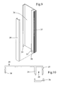
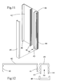
- FIGS 1, 3, 5, 7, 9 and 11 show six different executions in perspective of modular elements according to the invention.
- FIGs 2, 4, 6, 8, 10 and 12 show plan views of the elements respective modular modules of Figures 1, 3, 5, 7, 9 and 11.
- Fig. 13 is a perspective view of a partial wall constructed with elements of Figure 1.
- a first embodiment is shown in Figures 1 and 2. It is constituted a box comprising two horizontal walls 1, 2, two walls vertical 3, 4 joined by a third vertical wall 5.
- the vertical wall 5 extends on the right side and a fourth vertical wall 7 allows form with the wall 3 a vertical channel 6.
- the free edge of the wall vertical 4 is provided with a wing 4a whose length corresponds to the length of the canal 6.
- the horizontal walls 1 and 2 are narrower than the walls vertical walls 3 and 4.
- the wall 7 is narrower than the vertical walls 3 and 4.
- the outer faces of the walls 1, 2, 4, 7 are provided with male elements 8 and females 9 arranged so that when juxtaposing or superimposing two modular elements the so-called profiles collaborate to ensure the assembly of two elements. Adhesive or nails, screws, etc. can also come to ensure the mutual good tenuousness of the elements juxtaposed. Other means may be provided to ensure the assembly faces in contact, for example grooves facing each other in which slides a tongue.
- the wing 4a of the second element By juxtaposing on the right side of the element represented a second element, the wing 4a of the second element will close the open face of the channel 6.
- the fact that the wall 7 is narrower than the wall 4 of the second element, will leave a free space between the wing 4a of the second element and the edge of the wall 7 of the first element for the eventual passage of cables, water pipes, etc.
- a wall Interior facing
- a free space will remain between said wall and the free edges of horizontal walls 1 and 2 ensuring the passage of cables water pipes and of course providing vertical ventilation.
- the cavities formed by the four walls 1 to 4 receive an insulator.
- Canals verticals 6 either they contain the studs of the carrier frame either they constitute technical sleeves or remain empty and contain only the insulation.
- the posts are either wood, steel or cast concrete. In the latter case the channels 6 can form directly the formwork to pour the concrete. In this case we complete the empty space between the edge of the wall 7 and the wing 4a with a board for form a completely closed formwork.
- FIGS. 3 and 4 also comprises a shaped box two horizontal walls 10, 11, two vertical walls 12, 13 joined by a vertical wall 14.
- the vertical wall 14 extends on the right side and form with a fourth vertical wall 15 and the wall 12 a vertical channel 17.
- the horizontal walls 10 and 11 are narrower than the walls 12, 13 for the reason explained above in relation to the FIGS. 1 and 2.
- the wall 15 also has the same width as the walls 12 and 13, because to close the channel a conjugate closure element 16 is used.
- side walls 10, 11, 13 and 15 are also provided with male profiles and females for nesting when juxtaposing or superimposing these elements.
- This modular element allows to close and open the vertical channels to willingness to carry out the installation of insulation, technical sleeves etc.
- the third variant embodiment allows a greater flexibility during assembly. Indeed, we have a first structure box-shaped comprising two vertical walls 20, 21 two walls horizontal 18, 19 months wide than the walls 20, 21 and a vertical wall 22 bringing together the other four.
- the vertical channel 26 is formed by a second structure comprising two vertical and parallel walls 23, 24 and third perpendicular 25 joining the other two. Channel 26 will be closed by a closed and removable closure element 27.
- the faces walls 18, 19, 20, 23, 24 are provided with male profiles and females to ensure the nesting of these walls during the juxtaposition and superposition of these structures.
- the advantage of this variant is that you have more flexibility concerning the position of the vertical channels 26 because one can, for example, juxtapose two large caissons 18 to 22 and then only the structure 23 to 25 for the vertical channel.
- FIGS. 7 and 8 concerns a modular element similar to that of Figure 1 except that this element has the height of the wall. These elements are therefore intended to be juxtaposed only.
- the wall 31 extends on the right side and is provided with of a vertical wall 30, thus forming a channel 32.
- the free edge of the wall 28 is provided with a wing 33 whose length corresponds to the length of the canal 32.
- the modular element of FIGS. 9 and 10 is similar to that of FIGS. 4 except that the height of this element corresponds to the height of the wall for the element of Figures 7 and 8. It comprises two vertical walls and parallel 34, 35 joined by a third vertical wall 36.
- the wall 36 extends from the right side and is provided with a wall 37 parallel to the walls 34 and 35.
- the walls 35, 36 and 37 form the channel 38 which will be closed by an element 36.
- the establishment of these elements to form the wall is similar to previous executions ..
- FIGS. 11, 12 are similar to that of FIGS. except that these structures have the height of the wall and are intended to be only juxtaposed.
- the first structure comprises two side walls 40, 41 joined by a third vertical wall 42.
- the second structure is intended to form a vertical channel 50 to house the posts and sleeves and includes two parallel vertical walls 43, 44 joined together by a third wall 45. The channel thus formed will be closed by a 46.
- These structures have the same characteristics advantages than those of the structures of Figures 5 and 6.
- the vertical walls joining the walls side are the outer face of the wall.
- Interior siding will be constituted by walls in the form of panels of any kind may be fixed on the fields and, where appropriate, the wings of these elements Modular.
- Modular elements are prefabricated at the factory according to dimensions selected. They can be in any material used in construction, wood, plaster, chipboard, polymer wood, terracotta etc.
Landscapes
- Engineering & Computer Science (AREA)
- Architecture (AREA)
- Civil Engineering (AREA)
- Structural Engineering (AREA)
- Physics & Mathematics (AREA)
- Electromagnetism (AREA)
- Load-Bearing And Curtain Walls (AREA)
- Forms Removed On Construction Sites Or Auxiliary Members Thereof (AREA)
Applications Claiming Priority (2)
| Application Number | Priority Date | Filing Date | Title |
|---|---|---|---|
| FR0400092A FR2864835B1 (fr) | 2004-01-07 | 2004-01-07 | Elements modulaires de construction pour mur isole a structure porteuse |
| FR0400092 | 2004-01-07 |
Publications (1)
| Publication Number | Publication Date |
|---|---|
| EP1553240A1 true EP1553240A1 (de) | 2005-07-13 |
Family
ID=34586470
Family Applications (1)
| Application Number | Title | Priority Date | Filing Date |
|---|---|---|---|
| EP04029788A Withdrawn EP1553240A1 (de) | 2004-01-07 | 2004-12-16 | Modularbauelemente für tragende isolierte Wände |
Country Status (2)
| Country | Link |
|---|---|
| EP (1) | EP1553240A1 (de) |
| FR (1) | FR2864835B1 (de) |
Citations (5)
| Publication number | Priority date | Publication date | Assignee | Title |
|---|---|---|---|---|
| US2171338A (en) * | 1938-09-29 | 1939-08-29 | William P Witherow | Building member and construction |
| US4045937A (en) * | 1973-06-21 | 1977-09-06 | Credelca A.G. | Method of constructing a prefabricated room element and a building of a plurality of said elements |
| FR2644817A1 (fr) | 1989-01-10 | 1990-09-28 | Lefaucheux Jean Paul | Module pour construction de mur a ossature bois et procede d'assemblage de ces modules |
| FR2686108A1 (fr) * | 1986-03-21 | 1993-07-16 | Pierrel Guy | Procede de construction en beton arme ou similaire avec plots de fondation et elements de murs prefabriques a longrines incorporees et talon de pose pour elements de plancher et composants pour sa mise en óoeuvre. |
| US6041562A (en) * | 1998-02-17 | 2000-03-28 | Mar-Mex Canada Inc. | Composite wall construction and dwelling therefrom |
-
2004
- 2004-01-07 FR FR0400092A patent/FR2864835B1/fr not_active Expired - Fee Related
- 2004-12-16 EP EP04029788A patent/EP1553240A1/de not_active Withdrawn
Patent Citations (5)
| Publication number | Priority date | Publication date | Assignee | Title |
|---|---|---|---|---|
| US2171338A (en) * | 1938-09-29 | 1939-08-29 | William P Witherow | Building member and construction |
| US4045937A (en) * | 1973-06-21 | 1977-09-06 | Credelca A.G. | Method of constructing a prefabricated room element and a building of a plurality of said elements |
| FR2686108A1 (fr) * | 1986-03-21 | 1993-07-16 | Pierrel Guy | Procede de construction en beton arme ou similaire avec plots de fondation et elements de murs prefabriques a longrines incorporees et talon de pose pour elements de plancher et composants pour sa mise en óoeuvre. |
| FR2644817A1 (fr) | 1989-01-10 | 1990-09-28 | Lefaucheux Jean Paul | Module pour construction de mur a ossature bois et procede d'assemblage de ces modules |
| US6041562A (en) * | 1998-02-17 | 2000-03-28 | Mar-Mex Canada Inc. | Composite wall construction and dwelling therefrom |
Also Published As
| Publication number | Publication date |
|---|---|
| FR2864835A1 (fr) | 2005-07-08 |
| FR2864835B1 (fr) | 2007-11-23 |
Similar Documents
| Publication | Publication Date | Title |
|---|---|---|
| LU82807A1 (fr) | Blocs pour construire des murs et des immeubles et procede de construction | |
| FR2554479A1 (fr) | Systeme de blocs de construction pour eriger des edifices | |
| CA2291591A1 (fr) | Ossature de batiment | |
| FR2488930A1 (fr) | Procede et ensemble d'elements prefabriques auto-coffrants et auto-bloquants pour l'erection d'un batiment a chainage continu incorpore et a armature integree et batiments obtenus | |
| FR2949240A1 (fr) | Element de construction d'une paroi murale | |
| FR2556387A1 (fr) | Element de construction du type en polystyrene expanse, destine a la realisation de mur | |
| FR2818998A1 (fr) | Procede pour la realisation d'ouvrages de genie civil, et notamment de piscines ou bassins de retenue d'eau, et moyens pour sa mise en oeuvre | |
| EP0093030B1 (de) | Tiefraum, insbesondere ein Keller und Einrichtungsverfahren desselben | |
| LU83889A1 (fr) | Bloc de construction creux et systeme de blocs de construction | |
| EP1838932A1 (de) | Massivwand und herstellungsverfahren | |
| EP2495374B1 (de) | Konstruktion zur Behausung mit tragenden Mauern und Decken aus Beton-Fertigplatten. | |
| EP1211355A1 (de) | Unterbaumauer für eine Konstruktion und Verwirklichungsverfahren | |
| FR2864835A1 (fr) | Elements modulaires de construction pour mur isole a structure porteuse | |
| BE1008399A6 (fr) | Bloc de construction evide interieurement, destine a recevoir un coulis durcissable. | |
| BE1015141A3 (fr) | Ossature de batiment. | |
| EP0365512A1 (de) | Vorgefertigte Bauelemente zur Errichtung von Gebaüden und Bauverfahren zur Errichtung von Gebaüden mittels dieser Bauelemente | |
| BE1012779A6 (fr) | Armature et construction comprenant une telle armature. | |
| FR2900173A1 (fr) | Ensemble d'elements calibres en beton utilisable pour les constructions | |
| EP0083891A1 (de) | Vorgefertigte Platten zur Erstellung von Gebäuden | |
| FR2746128A1 (fr) | Coffrage pour la construction de troncons prefabriques de batiments, et batiments edifies au moyen de tels troncons | |
| BE751063Q (fr) | Perfectionnements aux edifices prefabriques a plusieurs etages | |
| FR2616168A1 (fr) | Procede d'assemblage d'elements de construction, moyens mettant en oeuvre ce procede et constructions ainsi realisees et/ou pourvues de ces moyens | |
| FR2545136A1 (fr) | Batiment en elements prefabriques et plus precisement caveau funeraire | |
| FR2904341A1 (fr) | Paroi de mur autour de structures porteuses | |
| FR2593214A1 (fr) | Elements modulaires prefabriques pour construction de piscines et procede de fabrication (coffrages perdus) |
Legal Events
| Date | Code | Title | Description |
|---|---|---|---|
| PUAI | Public reference made under article 153(3) epc to a published international application that has entered the european phase |
Free format text: ORIGINAL CODE: 0009012 |
|
| AK | Designated contracting states |
Kind code of ref document: A1 Designated state(s): AT BE BG CH CY CZ DE DK EE ES FI FR GB GR HU IE IS IT LI LT LU MC NL PL PT RO SE SI SK TR |
|
| AX | Request for extension of the european patent |
Extension state: AL BA HR LV MK YU |
|
| 17P | Request for examination filed |
Effective date: 20051221 |
|
| AKX | Designation fees paid |
Designated state(s): AT BE BG CH CY CZ DE DK EE ES FI FR GB GR HU IE IS IT LI LT LU MC NL PL PT RO SE SI SK TR |
|
| 17Q | First examination report despatched |
Effective date: 20071214 |
|
| STAA | Information on the status of an ep patent application or granted ep patent |
Free format text: STATUS: THE APPLICATION IS DEEMED TO BE WITHDRAWN |
|
| 18D | Application deemed to be withdrawn |
Effective date: 20080625 |