EP1553236A1 - Bloc - Google Patents
Bloc Download PDFInfo
- Publication number
- EP1553236A1 EP1553236A1 EP03799184A EP03799184A EP1553236A1 EP 1553236 A1 EP1553236 A1 EP 1553236A1 EP 03799184 A EP03799184 A EP 03799184A EP 03799184 A EP03799184 A EP 03799184A EP 1553236 A1 EP1553236 A1 EP 1553236A1
- Authority
- EP
- European Patent Office
- Prior art keywords
- face
- sloping face
- hand
- base body
- block
- Prior art date
- Legal status (The legal status is an assumption and is not a legal conclusion. Google has not performed a legal analysis and makes no representation as to the accuracy of the status listed.)
- Granted
Links
Images


Classifications
-
- E—FIXED CONSTRUCTIONS
- E04—BUILDING
- E04B—GENERAL BUILDING CONSTRUCTIONS; WALLS, e.g. PARTITIONS; ROOFS; FLOORS; CEILINGS; INSULATION OR OTHER PROTECTION OF BUILDINGS
- E04B2/00—Walls, e.g. partitions, for buildings; Wall construction with regard to insulation; Connections specially adapted to walls
- E04B2/02—Walls, e.g. partitions, for buildings; Wall construction with regard to insulation; Connections specially adapted to walls built-up from layers of building elements
- E04B2/04—Walls having neither cavities between, nor in, the solid elements
- E04B2/06—Walls having neither cavities between, nor in, the solid elements using elements having specially-designed means for stabilising the position
- E04B2/08—Walls having neither cavities between, nor in, the solid elements using elements having specially-designed means for stabilising the position by interlocking of projections or inserts with indentations, e.g. of tongues, grooves, dovetails
-
- E—FIXED CONSTRUCTIONS
- E04—BUILDING
- E04B—GENERAL BUILDING CONSTRUCTIONS; WALLS, e.g. PARTITIONS; ROOFS; FLOORS; CEILINGS; INSULATION OR OTHER PROTECTION OF BUILDINGS
- E04B2/00—Walls, e.g. partitions, for buildings; Wall construction with regard to insulation; Connections specially adapted to walls
- E04B2/02—Walls, e.g. partitions, for buildings; Wall construction with regard to insulation; Connections specially adapted to walls built-up from layers of building elements
- E04B2/04—Walls having neither cavities between, nor in, the solid elements
- E04B2/12—Walls having neither cavities between, nor in, the solid elements using elements having a general shape differing from that of a parallelepiped
-
- E—FIXED CONSTRUCTIONS
- E04—BUILDING
- E04C—STRUCTURAL ELEMENTS; BUILDING MATERIALS
- E04C1/00—Building elements of block or other shape for the construction of parts of buildings
-
- E—FIXED CONSTRUCTIONS
- E04—BUILDING
- E04B—GENERAL BUILDING CONSTRUCTIONS; WALLS, e.g. PARTITIONS; ROOFS; FLOORS; CEILINGS; INSULATION OR OTHER PROTECTION OF BUILDINGS
- E04B2/00—Walls, e.g. partitions, for buildings; Wall construction with regard to insulation; Connections specially adapted to walls
- E04B2/02—Walls, e.g. partitions, for buildings; Wall construction with regard to insulation; Connections specially adapted to walls built-up from layers of building elements
- E04B2002/0202—Details of connections
- E04B2002/0204—Non-undercut connections, e.g. tongue and groove connections
- E04B2002/0206—Non-undercut connections, e.g. tongue and groove connections of rectangular shape
-
- E—FIXED CONSTRUCTIONS
- E04—BUILDING
- E04B—GENERAL BUILDING CONSTRUCTIONS; WALLS, e.g. PARTITIONS; ROOFS; FLOORS; CEILINGS; INSULATION OR OTHER PROTECTION OF BUILDINGS
- E04B2/00—Walls, e.g. partitions, for buildings; Wall construction with regard to insulation; Connections specially adapted to walls
- E04B2/02—Walls, e.g. partitions, for buildings; Wall construction with regard to insulation; Connections specially adapted to walls built-up from layers of building elements
- E04B2002/0202—Details of connections
- E04B2002/0204—Non-undercut connections, e.g. tongue and groove connections
- E04B2002/0226—Non-undercut connections, e.g. tongue and groove connections with tongues and grooves next to each other on the end surface
-
- E—FIXED CONSTRUCTIONS
- E04—BUILDING
- E04B—GENERAL BUILDING CONSTRUCTIONS; WALLS, e.g. PARTITIONS; ROOFS; FLOORS; CEILINGS; INSULATION OR OTHER PROTECTION OF BUILDINGS
- E04B2/00—Walls, e.g. partitions, for buildings; Wall construction with regard to insulation; Connections specially adapted to walls
- E04B2/02—Walls, e.g. partitions, for buildings; Wall construction with regard to insulation; Connections specially adapted to walls built-up from layers of building elements
- E04B2002/0202—Details of connections
- E04B2002/0232—Undercut connections, e.g. using undercut tongues and grooves
-
- E—FIXED CONSTRUCTIONS
- E04—BUILDING
- E04B—GENERAL BUILDING CONSTRUCTIONS; WALLS, e.g. PARTITIONS; ROOFS; FLOORS; CEILINGS; INSULATION OR OTHER PROTECTION OF BUILDINGS
- E04B2/00—Walls, e.g. partitions, for buildings; Wall construction with regard to insulation; Connections specially adapted to walls
- E04B2/02—Walls, e.g. partitions, for buildings; Wall construction with regard to insulation; Connections specially adapted to walls built-up from layers of building elements
- E04B2002/0202—Details of connections
- E04B2002/0243—Separate connectors or inserts, e.g. pegs, pins or keys
- E04B2002/0254—Tie rods
-
- E—FIXED CONSTRUCTIONS
- E04—BUILDING
- E04B—GENERAL BUILDING CONSTRUCTIONS; WALLS, e.g. PARTITIONS; ROOFS; FLOORS; CEILINGS; INSULATION OR OTHER PROTECTION OF BUILDINGS
- E04B2/00—Walls, e.g. partitions, for buildings; Wall construction with regard to insulation; Connections specially adapted to walls
- E04B2/02—Walls, e.g. partitions, for buildings; Wall construction with regard to insulation; Connections specially adapted to walls built-up from layers of building elements
- E04B2002/0256—Special features of building elements
- E04B2002/0267—Building elements with the appearance of several bricks
Definitions
- the present invention relates to blocks that enable a structure to be assembled by arranging the blocks in a side-by-side fashion with parts thereof fitted to each other.
- a block (1) is disclosed in WO00/43606.
- the block is formed with engaging parts (2, 2), a fitting protrusion (3), a fitting groove (4), and an insertion hole (5), and a plurality of blocks (1) can be stacked one upon another to thereby assemble a wall (structure) of a house or the like.
- To assemble these blocks (1) into a structure while connecting laterally adjacent blocks (1) by fitting the engaging parts thereof to each other, each of the blocks (1) is stacked on another block positioned immediately below by fitting the fitting groove thereof on the fitting protrusion of the block positioned immediately below. This method makes it possible to assemble a highly airtight structure which is capable of preventing infiltration of rain water.
- each block (1) in order to assemble a structure, each block (1) is pushed in downward, whereby the engaging parts are engaged with the respective associated engaging parts of other blocks and the fitting groove thereof is fitted on the fitting protrusion of another block.
- this block is formed such that when the structure is assembled, a gap is not produced between each of the faces (e.g. a side face (21a) of an engaging part) defining the engaging parts, the fitting protrusion, and the fitting groove and the faces of the opposite lateral sides of the main body of the block, and the associated one of the faces of the other blocks to be fitted.
- the present invention has been made to solve the problems described above, and a main object thereof is to provide blocks which can be easily assembled into a highly airtight structure.
- the block according to the present invention is a block for enabling a structure to be assembled by arranging blocks in a side-by-side fashion with parts thereof fitted to each other, wherein a base body part positioned in a central portion of the block and having upper and lower faces formed such that the upper and lower faces are flat and parallel to each other, a first protruding part protruding leftward from the base body part, and a second protruding part protruding rightward from the base body part are integrally formed with the base body part, wherein the base body part has sloping faces formed from a lower end of a left lower side face of the base body part to a protrusion of the first protruding part, and from a lower end of a right lower side face of the base body part to a protrusion of the second protruding part, such that as the sloping faces extend upward, the sloping faces become more distant from a central vertical axis of the block in a left-right direction, and sloping faces
- the left and right lower side faces and left and right upper side faces of the base body part are formed as the respective sloping faces.
- the lower surface, upper surface and left side surface of the first protruding part protruding leftward from the base body part and the lower surface, upper surface and right side surface of a second protruding part protruding rightward from the base body part are each formed by a plurality of sloping faces.
- the faces of the lower portion of the block are each formed with a fitting groove, while the faces of the upper portion of the block are each formed with a fitting protrusion.
- a right-hand half body and a left-hand half body are formed in rotationally symmetrical relationship with respect to the central vertical axis.
- a branch part having a same shape as a shape of a right-hand or left-hand half body of the block is formed in a manner protruding from at least one of front and back surfaces of the block.
- an insertion hole through which a bar-like reinforcing member can be inserted is formed vertically through the block.
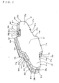
- FIG. 1 is a perspective view of a building block 1
- FIG. 2 is a front view of the building block 1;
- FIG. 3 is a bottom view of the building block 1
- FIG. 4 is a cross-sectional view of the building block 1 taken on line A-A in FIG. 2;
- FIG. 5 is a plan view of the building block 1
- FIG. 6 is a front view of a structure assembled using the building blocks 1;
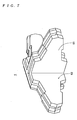
- FIG. 7 is a perspective view of a building block 4.
- FIG. 8 is a front view of a building block 5;
- FIG. 9 is a front view of a structure assembled using the building blocks 5.
- the building blocks 1 enable a wall-like structure to be assembled by arranging the same in a side-by-side fashion with parts thereof fitted to each other.
- the building block 1 has reinforcing steel rods embedded therein, and is generally formed of concrete such that it has a plate shape with a predetermined thickness.
- the building block 1 is integrally formed by a base body part 11 and protruding parts 21 and 31 protruding leftward and rightward, respectively, from the base body part 11 such that the building block 1 is generally cross-shaped in front view.
- the building block 1 is formed such that the right-hand half body thereof and the left-hand half body thereof are rotationally symmetrical with respect to a central vertical axis Vc (see FIG.
- the base body part 11 is located in the central portion of the building block 1, and has a lower face 11a thereof and an upper face 11b thereof which are flat and in parallel relationship to each other. Further, the base body part 11 has a left lower side face 11c thereof and a right lower side face 11d thereof formed as respective sloping faces such that as they extend upward from the lower face 11a, they become more distant from the central vertical axis Vc. Furthermore, the base body part 11 has a left upper side face 11e thereof and a right upper side face 11f thereof formed as respective sloping faces such that as they extend downward from the upper face 11b, they become more distant from the central vertical axis Vc.
- the lower face 11a, left lower side face 11c and right lower side face 11d of the base body part 11 are formed with respective fitting grooves 12a, 12c and 12d (hereinafter also simply referred to as "the fitting groove(s) 12" when it is not necessary to distinguish between them) extending along the respective faces in the left-right direction in a continuous manner.
- the fitting grooves 12a, 12c and 12d are formed in the respective central portions, in the direction of thickness, of the lower face 11a, the left lower side face 11c and the right lower side face 11d. Further, as shown in FIG.
- each of the fitting grooves 12 is formed into a rectangular cross-sectional shape having a width L2 which is approximately one third as long as a thickness L1 of the building block 1, and a depth L3 which is approximately two thirds as long as the width L2.
- the upper face 11b, left upper side face 11e and right upper side face 11f of the base body part 11 has respective fitting protrusions 13b, 13e and 13f (hereinafter also simply referred to as "the fitting protrusion(s) 13" when it is not necessary to distinguish between them) extending along the respective faces in the left-right direction in a continuous manner.
- the fitting protrusion(s) 13 hereinafter also simply referred to as "the fitting protrusion(s) 13" when it is not necessary to distinguish between them
- each of the fitting protrusions 13b, 13e and 13f are formed in the respective central portions, in the direction of thickness, of the upper face 11b, the left upper side face 11e and the right upper side face 11f. Further, as shown in FIG. 4, each of the fitting protrusions 13 is formed into a rectangular cross-sectional shape having a width L4 which is approximately one third as long as the thickness L1 of the building block 1, and a height L5 which is approximately two thirds as long as the width L4. Thus, each of the fitting protrusions 13 has the same or substantially the same cross-sectional shape as that of the fitting groove 12.
- the protruding part 21 corresponds to a first protruding part according to the present invention, and is formed in a manner protruding leftward from the base body part 11 as shown in FIG. 1.
- the protruding part 21 has a lower surface thereof formed by left sloping faces 21a to 21c corresponding, respectively, to first to third left sloping faces according to the present invention.
- the protruding part 21 has an upper surface thereof formed by left sloping faces 21d to 21f corresponding, respectively, to fourth to sixth left sloping faces according to the present invention, and a left side surface thereof formed by left sloping faces 21g and 21h corresponding, respectively, to seventh and eighth left sloping faces according to the present invention.
- the left sloping face 21a is formed continuous with the left end (protruding portion according to the present invention) of the left lower side face 11c of the base body part 11 such that as the left sloping face 21a extends leftward, it becomes closer to a central horizontal axis Hc located at the center in the vertical direction of the building block 1 and in the direction of thickness of the same.
- the left sloping face 21b is formed continuous with the left end of the left sloping face 21a such that as the left sloping face 21b extends leftward, it becomes more distant from the central horizontal axis Hc.
- the left sloping face 21b is formed in a manner inclined at approximately 90 degrees (preferably 90 degrees) to the left sloping face 21a.
- the left sloping face 21c is formed continuous with the left end of the left sloping face 21b such that as the left sloping face 21c extends leftward, it becomes closer to the central horizontal axis Hc.
- the left sloping face 21c is formed in a manner inclined at approximately 90 degrees (preferably 90 degrees) to the left sloping face 21b.
- the left sloping faces 21a and 21c are formed in substantially parallel relationship (preferably parallel) to each other.
- the left sloping face 21d is formed continuous with the left end (protruding portion according to the present invention) of the left upper side face 11e of the base body part 11 such that as the left sloping face 21d extends leftward, it becomes closer to the central horizontal axis Hc.
- the left sloping face 21e is formed continuous with the left end of the left sloping face 21d such that as the left sloping face 21e extends leftward, it becomes more distant from the central horizontal axis Hc.
- the left sloping face 21e is formed in a manner inclined at approximately 90 degrees (preferably 90 degrees) to the left sloping face 21d.
- the left sloping face 21f is formed continuous with the left end of the left sloping face 21e such that as the left sloping face 21f extends leftward, it becomes closer to the central horizontal axis Hc.
- the left sloping face 21f is formed in a manner inclined at approximately 90 degrees (preferably 90 degrees) to the left sloping face 21e.
- the left sloping faces 21d and 21f are formed in substantially parallel relationship (preferably parallel) to each other.
- the left sloping face 21g is formed continuous with the left end of the left sloping face 21c such that the left sloping face 21g extends parallel with the right lower side face 11f of the base body part 11.
- the left sloping face 21h is formed continuous with the left end of the left sloping face 21f such that the left sloping face 21h extends parallel with the right lower side face 11d of the base body part 11.
- the left sloping faces 21g and 21h have left ends thereof connected to each other to form the left side surface of the protruding part 21.
- the left sloping faces 21a to 21c and 21g of the protruding part 21 are formed with respective fitting grooves 22a to 22c and 22g (hereinafter also simply referred to as "the fitting groove(s) 22" when it is not necessary to distinguish between them) extending along the respective faces in the left-right direction in a continuous manner.
- the fitting groove 22a is formed in a manner continuous with the fitting groove 12c of the base body part 11.
- the fitting grooves 22a to 22c and 22g are formed such that they extend along the central portions, in the direction of thickness, of the respective left sloping faces 21a to 21c and 21g.
- each of the fitting grooves 22 has the same or substantially the same cross-sectional shape as that of the fitting groove 12 of the base body part 11.
- the left sloping faces 21d to 21f and 21h of the protruding part 21 have respective fitting protrusions 23d to 23f and 23h (hereinafter also simply referred to as "the fitting protrusion(s) 23" when it is not necessary to distinguish between them) extending along the respective faces in the left-right direction in a continuous manner.
- the fitting protrusion 23d is formed in a manner continuous with the fitting protrusion 13e of the base body part 11. As shown in FIG.
- the fitting protrusions 23d to 23f and 23h are formed such that they extend along the respective central portions, in the direction of thickness, of the left sloping faces 21d to 21f and 21h. Further, each of the fitting protrusions 23 has the same or substantially the same cross-sectional shape as that of the fitting protrusion 13 of the base body part 11.
- the protruding part 31 corresponds to a second protruding part according to the present invention, and is formed in a manner protruding rightward from the base body part 11 as shown in FIG. 1.
- the protruding part 31 has a lower surface thereof formed by left sloping faces 31a to 31c corresponding, respectively, to first to third right sloping faces according to the present invention.
- the protruding part 31 has an upper surface thereof formed by right sloping faces 31d to 31f corresponding, respectively, to fourth to sixth right sloping faces according to the present invention, and a right side surface thereof formed by right sloping faces 31g and 31h corresponding, respectively, to seventh and eighth right sloping faces according to the present invention.
- the right sloping face 31a is formed continuous with the right end (protruding portion according to the present invention) of the right lower side face 11d of the base body part 11 such that the right sloping face 31a extends parallel with the left sloping face 21f of the protruding part 21.
- the right sloping face 31b is formed continuous with the right end of the right sloping face 31a such that the right sloping face 31b extends parallel with the left sloping face 21e.
- the right sloping face 31c is formed continuous with the right end of the right sloping face 31b such that the right sloping face 31c extends parallel with the left sloping face 21d.
- the right sloping face 31d is formed continuous with the right end (protruding portion according to the present invention) of the right upper side face 11f of the base body part 11 such that the right sloping face 31d extends parallel with the left sloping face 21c of the protruding part 21.
- the right sloping face 31e is formed continuous with the right end of the right sloping face 31d such that the right sloping face 31e extends parallel with the left sloping face 21b.
- the right sloping face 31f is formed continuous with the right end of the right sloping face 31e such that the right sloping face 31f extends parallel with the left sloping face 21a.
- the right sloping faces 31d and 31f are formed parallel or substantially parallel with each other.
- the right sloping face 31g is formed continuous with the right end of the right sloping face 31c such that the right sloping face 31g extends parallel with the left upper side face 11e of the base body part 11.
- the right sloping face 31h is formed continuous with the right end of the right sloping face 31f such that the right sloping face 31h extends parallel with the left lower side face 11c of the base body part 11.
- the right sloping faces 31g and 31h have right ends thereof connected to each other to form the right side surface of the protruding part 31.
- the right sloping faces 31a to 31c and 31g of the protruding part 31 are formed with respective fitting grooves 32a to 32c and 32g (hereinafter also simply referred to as "the fitting groove(s) 32" when it is not necessary to distinguish between them) extending along the respective faces in the left-right direction in a continuous manner.
- the fitting groove 32a is formed in a manner continuous with the fitting 12d of the base body part 11.
- the fitting grooves 32a to 32c and 32g are formed such that they extend along the central portions, in the direction of thickness, of the respective right sloping faces 31a to 31c and 31g.
- each of the fitting grooves 32 has the same or substantially the same cross-sectional shape as that of the fitting groove 12.
- the right sloping faces 31d to 31f and 31h of the protruding part 31 have respective fitting protrusions 33d to 33f and 33h (hereinafter also simply referred to as "the fitting protrusion(s) 33" when it is not necessary to distinguish between them) extending along the respective faces in the left-right direction in a continuous manner.
- the fitting protrusion 33d is formed in a manner continuous with the fitting protrusion 13f of the base body part 11. As shown in FIG.
- the fitting protrusions 33d to 33f and 33h are formed such that they extend along the respective central portions, in the direction of thickness, of the right sloping faces 31d to 31f and 31h. Further, each of the fitting protrusions 33 has the same or substantially the same cross-sectional shape as that of the fitting protrusion 13.
- the fitting groove 12a of one building block 1 is fitted on the fitting protrusion 13b of another building block 1 positioned immediately below, and the fitting protrusion 13b of the one building block 1 is fitted in the fitting groove 12a of still another building block 1 positioned immediately above.
- the fitting groove 12c and the fitting grooves 22 of the one building block 1 are fitted, respectively, on the fitting protrusions 33 and fitting protrusion 13f of another building block 1 positioned at the lower left of the one building block 1, and the fitting groove 12d and the fitting grooves 32 of the same are fitted, respectively, on the fitting protrusions 23 and fitting protrusion 13e of another building block 1 positioned at the lower right.
- fitting protrusions 23 and fitting protrusion 13e of the one building block 1 are fitted, respectively, in the fitting groove 12d and the fitting grooves 32 of another building block 1 positioned at the upper left, and the fitting protrusions 33 and fitting protrusion 13f of the same are fitted, respectively, in the fitting groove 12c and the fitting grooves 22 of another building block 1 positioned at the upper right.
- Each of the faces formed with the respective fitting grooves or fitting protrusions is held in intimate contact with the associated one of the fitting grooves or fitting protrusions of an adjacent one of the other building blocks 1, 1, ..., whereby high airtightness of the assembled structure (particularly at the fitted portions of the fitting grooves and the fitting protrusions) can be ensured.
- the base block 2 is formed such that an upper portion thereof has the same or substantially the same shape as that of the upper half body of the building block 1, and a lower portion thereof as a base part has the shape of e.g. a rectangular parallelepiped.
- the base block 3 is formed such that a base body part thereof has the shape of a rectangular parallelepiped and a width equal to the length, in the left-right direction, of the fitting protrusion 13b of the building block 1, with a fitting protrusion formed on the top surface of the base body part such that the fitting protrusion has the same shape as that of the fitting protrusion 13b.
- the base blocks 2 and the base blocks 3 are positioned alternately, and then fixed by burying the base body part of each base block underground or connecting the same onto a concrete foundation or the like e.g. by bolts.
- a building block 1 (for example, a building block 1A shown in the figure) is moved downward from above to be positioned between two adjacent base blocks 2 (for example, between a base block 2A and a base block 2B shown in the figure (i.e. on the upper side of a base block 3A shown in the figure)).
- the fitting grooves 22g, 22c, 22b, 22a, and 12c of the building block 1A are fitted on the fitting protrusions 13f, 33d to 33f, and 33h of the base block 2A, respectively, and the fitting groove 12a of the building block 1A is fitted on the fitting protrusion of the base block 3A.
- the fitting grooves 12d, 32a to 32c, and 32g of the building block 1A are fitted on the fitting protrusions 23h, 23f, 23e, 23d, and 13e of the base block 2B, respectively.
- the left sloping faces 21g, 21c, 21b and 21a and left lower side face 11c of the building block 1A approach the right upper side face 11f and right sloping faces 31d, 31e, 31f and 31h of the base block 2A, respectively, and the lower face 11a of the building block 1A approaches the top surface of the base body part of the base block 3A.
- the right lower side face 11d and right sloping faces 31a, 31b, 31c and 31g of the building block 1A approach the left sloping faces 21h, 21f, 21e and 21d and left upper side face 11e of the base block 2B, respectively, and finally the associated faces come into contact with each other.
- the faces are each formed as a sloping face, the downward movement of the building block 1A does not cause friction, so that the building block 1A can be positioned simply by its own weight or with a slight force.
- the building block 1A In the state where the building block 1A is positioned, the building block 1A is supported by the faces of the base blocks 2A, 2B and 3A in contact with the associated faces of the building block 1A, so that the downward movement of the building block 1A is stopped. Further, when the building block 1A attempts to move leftward, the right sloping face 31h and right upper side face 11f of the base block 2A and the left sloping face 21e of the base block 2B come into abutment with the left lower face 11c, left sloping face 21g and right sloping face 31b of the building block 1A, respectively, so that the leftward movement of the building block 1A is stopped.
- the building block 1A attempts to move rightward, the right lower face 11d, right sloping face 31g and left sloping face 21b of the building block 1A come into abutment with the left sloping face 21h and left upper side face 11e of the base block 2B and the right sloping face 31e of the base block 2A, respectively, so that the rightward movement of the building block 1A is stopped. Further, when the building block 1A attempts to move in the direction of its thickness, faces forming the fitting grooves of the building block 1A come into abutment with faces forming the fitting protrusions of the base blocks 2A, 2B and 3A, so that the movement of the building block 1A in the direction of its thickness is stopped.
- the building block 1A is fitted to the base blocks 2A, 2B and 3A without moving downward, leftward and rightward, and in the direction of its thickness.
- the fitting grooves have the same or substantially the same cross-sectional shape as that of the fitting protrusions, the faces forming the fitting grooves and the faces forming the fitting protrusions are held in intimate contact with each other. Therefore, high airtightness is ensured at the fitted portions of the building block 1A and the base blocks 2A, 2B and 3A, which makes it possible to prevent infiltration of rain water from the front (back) surface of the building block 1A to the back (front) surface of the same.
- another building block 1 is positioned between the base block 2B and another base block 2, not shown, adjacent to the base block 2B.
- other building blocks 1, 1, ... are each positioned between the associated two of the other base blocks 2, 2, ... to thereby form a first row of building blocks arranged in a side-by-side fashion.
- the building block 1 since the building block 1 is formed such that the right-hand half body thereof and the left-hand half body thereof are rotationally symmetrical with respect to the central vertical axis Vc, the building block 1 can be used without distinguishing between the front and the back, which makes it possible to arrange the building blocks 1 efficiently.
- FIG. 6 building blocks 1, 1, ... are positioned from above the first row of building blocks 1, 1, ...
- each of the building blocks 1 can be positioned simply by its own weight or with a slight force as described hereinabove, so that it is possible to assemble a highly airtight structure with ease.
- building blocks used to form the side edge portions of the structure are each in the form of the right-hand half body of the building block 1 or the left-hand half body of the same, and building blocks used to form the top portion of the structure are each in the form of the lower half body of the building block 1.
- the base body part 11 has the left and right lower side faces 11c and 11d and the left and right upper side faces 11e and 11f each formed as a sloping face;
- the protruding part 21 has the lower surface thereof formed by the left sloping faces 21a to 21c, the upper surface thereof formed by the left sloping faces 21d to 21f, and the side surface thereof formed by the left sloping faces 21g and 21h;
- the protruding part 31 has the lower surface thereof formed by the right sloping faces 31a to 31c, the upper surface thereof formed by the right sloping faces 31d to 31f, and the side surface thereof formed by the right sloping faces 31g and 31h;
- the left sloping faces 21a to 21c and 21g, the left lower side face 11c, the lower face 11a, the right lower side face 11d, and the right sloping faces 31a to 31c and 31g are formed with the fitting grooves 22, 12 and 32, respectively, and the
- the building block 1 can be fitted to other building blocks 1 simply by its own weight or by pushing in the building block 1 with a slight force without causing friction between the associated faces, so that it is possible to easily assemble a structure which ensures high airtightness at the fitted portions of the fitting grooves 22, 12 and 32 and the fitting protrusions 23, 13 and 33.
- the building block 1 is formed such that the right-hand half body thereof and the left-hand half body thereof are rotationally symmetrical with respect to the central vertical axis, the building block 1 can be used without distinguishing between the front and the back in assembling the structure, which makes it possible to dispense with work for distinguishing between the front and the back, thereby enhancing working efficiency.
- the present invention is by no means limited to the above described construction.
- a building block 4 (another embodiment of the block according to the present invention) integrally formed with a branch part 61 having the same or substantially the same shape as that of the right-hand half body (or the left-hand half body) of the building block 1 and protruding perpendicularly from the central portion of one surface 62 as either the front surface or the back surface of a main body part thereof having the same shape as that of the building block 1, as shown in FIG. 7.
- this building block 4 one structure can have another structure connected thereto from a direction perpendicular to the one structure.
- the building block 4 in connecting the other structure to the one structure using the building block 4, first, the building block 4 is used in place of a building block 1 at a location where the other structure is connected. Then, a building block 1 is connected to the protruding end of the branch part 61 of the building block 4.
- this building block 4 since the branch part 61 is formed on the one surface 62, one structure can have another structure easily connected thereto.
- another branch part protruding from the opposite surface from the one surface in addition to the branch part 61 it is possible to form a building block having the shape of a cross in plan view such that other structures can be connected, respectively, to both the front and back of the one structure.
- a building block 5 (still another embodiment of the block according to the present invention) having a base body part 71 thereof formed vertically therethrough with insertion holes 72 and 72, as shown in FIG. 8, through each of which can be inserted e.g. a reinforcing bar (corresponding to a reinforcing member according to the present invention; see FIG. 9) 101 for reinforcing a structure.
- a reinforcing bar corresponding to a reinforcing member according to the present invention; see FIG. 9
- reinforcing bars 101, 101, ... are erected on base blocks 2 and 3 as shown in FIG. 9, and each of the reinforcing bars 101 is inserted through the associated insertion hole 72, whereby the building blocks 5 are arranged in a side-by-side fashion.
- This method facilitates assembly of a highly airtight and rigid structure. It should be noted that a pair of pipes through each of which a reinforcing bar 101 can be vertically inserted can be provided parallel to each other on the wall surface of the building block 1 instead of forming the insertion holes 72 and 72.
- the fitting grooves 12, 22 and 32 and the fitting protrusions 13, 23 and 33 are formed to have a rectangular cross-sectional shape
- the right-hand half body and the left-hand half body are formed in rotationally symmetrical relationship with respect to the central vertical axis Vc, the two half bodies can be formed asymmetrically, and this construction of a building block makes it possible to easily assemble a highly airtight structure, similarly to the construction of the building block 1.
- each building block 1 can be disposed upside down for assembly of a structure, and this assembly method can also facilitate assembly of a highly airtight structure.
- base blocks formed with a fitting groove are used in place of the base blocks 2 formed with the fitting protrusion.
- Structures which can be assembled using building blocks 1 include retaining walls for holding back earth, outer walls of large buildings, exteriors (including fences, gate doors, and gateposts), and other various kinds of structures.
- the building block 1 is formed using reinforcing bars and concrete, the present invention is by no means limited to the example, but a block can be formed of any one of various materials, such as metals (e.g. steel, aluminum, copper, and stainless, for example), glass (including glass wool), paper, stone, plastic (including foamed plastic), ceramic, wood (including chip materials), cloth, soil, and plants (including straw and bamboo).
- a plurality of kinds of the above-mentioned materials can be used to form a block, or a mixture of a plurality of kinds of the above-mentioned materials can also be used to form a block.
- blocks formed of these materials can be used to assemble outer walls, inner walls, roofs and floors of houses, outdoor or indoor stages (including temporary stages), and so forth.
- structures, such as models (including building models) and toys (block toys) using blocks formed of the materials.
- the left and right lower side faces and left and right upper side faces of its base body part are each formed as a sloping face.
- the lower surface, upper surface and left side surface of a first protruding part protruding leftward from the base body part and the lower surface, upper surface and right side surface of a second protruding part protruding rightward from the base body part are each formed by a plurality of sloping faces.
- the faces of the lower portion of the block are each formed with a fitting groove, while the faces of the upper portion of the block are each formed with a fitting protrusion.
- the block can be fitted to other blocks without causing friction between the associated faces and simply by its own weight or by pushing in the block with a slight force.
- This realizes a block that enables a structure to be easily assembled which ensures high airtightness at the fitted portions of blocks.
Landscapes
- Engineering & Computer Science (AREA)
- Architecture (AREA)
- Civil Engineering (AREA)
- Structural Engineering (AREA)
- Physics & Mathematics (AREA)
- Electromagnetism (AREA)
- Toys (AREA)
- Sewage (AREA)
- Foundations (AREA)
- Finishing Walls (AREA)
- Retaining Walls (AREA)
- Buckles (AREA)
Applications Claiming Priority (3)
| Application Number | Priority Date | Filing Date | Title |
|---|---|---|---|
| JP2002291030 | 2002-10-03 | ||
| JP2002291030 | 2002-10-03 | ||
| PCT/JP2003/012557 WO2004031502A1 (fr) | 2002-10-03 | 2003-09-30 | Bloc |
Publications (3)
| Publication Number | Publication Date |
|---|---|
| EP1553236A1 true EP1553236A1 (fr) | 2005-07-13 |
| EP1553236A4 EP1553236A4 (fr) | 2006-05-31 |
| EP1553236B1 EP1553236B1 (fr) | 2007-11-14 |
Family
ID=32063833
Family Applications (1)
| Application Number | Title | Priority Date | Filing Date |
|---|---|---|---|
| EP03799184A Expired - Lifetime EP1553236B1 (fr) | 2002-10-03 | 2003-09-30 | Bloc |
Country Status (9)
| Country | Link |
|---|---|
| US (1) | US7367167B2 (fr) |
| EP (1) | EP1553236B1 (fr) |
| KR (1) | KR100642664B1 (fr) |
| CN (1) | CN100582412C (fr) |
| AT (1) | ATE378479T1 (fr) |
| AU (1) | AU2003266723B2 (fr) |
| CA (1) | CA2500880C (fr) |
| DE (1) | DE60317547D1 (fr) |
| WO (1) | WO2004031502A1 (fr) |
Cited By (1)
| Publication number | Priority date | Publication date | Assignee | Title |
|---|---|---|---|---|
| WO2009156772A1 (fr) * | 2008-06-25 | 2009-12-30 | Dimitrios Mantikas | Élément structurel |
Families Citing this family (17)
| Publication number | Priority date | Publication date | Assignee | Title |
|---|---|---|---|---|
| US20050066594A1 (en) * | 2003-09-30 | 2005-03-31 | Stavenjord Walter Karl | Casing system |
| US8667752B2 (en) | 2010-06-25 | 2014-03-11 | Robert Pollack | Interlocking construction systems and methods |
| US8375665B2 (en) * | 2009-12-09 | 2013-02-19 | Modular Arts, Inc. | Partition modules and assembly system thereof |
| WO2013036271A1 (fr) * | 2011-09-08 | 2013-03-14 | Samobi Industries, Llc | Blocs de construction à emboîtement |
| CA2842448C (fr) | 2013-03-08 | 2016-01-19 | Pavestone, LLC | Pave porteur et procede d'installation |
| US10583588B2 (en) | 2013-06-21 | 2020-03-10 | Pavestone, LLC | Manufactured retaining wall block with improved false joint |
| USD791346S1 (en) | 2015-10-21 | 2017-07-04 | Pavestone, LLC | Interlocking paver |
| US9701046B2 (en) | 2013-06-21 | 2017-07-11 | Pavestone, LLC | Method and apparatus for dry cast facing concrete deposition |
| US9175473B2 (en) | 2013-08-19 | 2015-11-03 | Modular Arts, Inc. | Ceiling tile system |
| US9068351B1 (en) * | 2013-12-09 | 2015-06-30 | Samobi Industries, Llc | Interlocking construction blocks |
| USD737468S1 (en) | 2014-05-07 | 2015-08-25 | Pavestone, LLC | Front face of a retaining wall block |
| USD802168S1 (en) * | 2016-06-09 | 2017-11-07 | Fine Chemical Co., Ltd. | Artificial turf infill |
| USD803421S1 (en) * | 2016-06-09 | 2017-11-21 | Fine Chemical Co., Ltd. | Artificial turf infill |
| US20180328030A1 (en) * | 2016-07-14 | 2018-11-15 | Gregory Walter | Concrete Section and Method for Constructing a Wall |
| USD830579S1 (en) * | 2017-06-28 | 2018-10-09 | Ness Inventions, Inc. | Paver block |
| CN110820991B (zh) * | 2019-11-07 | 2021-07-13 | 湖北麻一建设有限公司 | 建筑节能自保温墙体及其施工方法 |
| USD1037491S1 (en) | 2021-12-14 | 2024-07-30 | Pavestone, LLC | Wall block |
Family Cites Families (16)
| Publication number | Priority date | Publication date | Assignee | Title |
|---|---|---|---|---|
| DE2110563A1 (de) | 1971-03-05 | 1972-09-14 | Manfred Dahlhaus | Verbundbaustein |
| US4227829A (en) * | 1978-11-29 | 1980-10-14 | Landry Jr Kossuth J | Soil erosion prevention blocks |
| WO1981002983A1 (fr) | 1980-04-24 | 1981-10-29 | A Marra | Briques ou blocs |
| EP0059820B1 (fr) * | 1981-03-10 | 1984-05-16 | Rolf Scheiwiller | Ensemble de pierres pour l'érection de murs |
| JPS5889511U (ja) * | 1981-06-29 | 1983-06-17 | 積水化成品工業株式会社 | 化粧コンクリ−トブロツク |
| JPS5889511A (ja) | 1981-11-25 | 1983-05-27 | Hitachi Koki Co Ltd | ネジ送り構造 |
| US4781492A (en) * | 1986-03-31 | 1988-11-01 | Kyowa Concrete Kogyo Co. Ltd. | Block for revetment |
| US5601384A (en) * | 1995-06-07 | 1997-02-11 | Keystone Retaining Wall Systems, Inc. | Plantable retaining wall |
| CN2235991Y (zh) * | 1995-12-01 | 1996-09-25 | 关鳞童 | 镶嵌式砌块 |
| USD399577S (en) * | 1996-02-23 | 1998-10-13 | Scales John M | Revetment block |
| US5921710A (en) * | 1997-02-27 | 1999-07-13 | Scales; John M. | Revetment blocks and method |
| US6071041A (en) * | 1998-10-27 | 2000-06-06 | Petratech, Inc. | Revetment block |
| AU762932B2 (en) * | 1999-01-21 | 2003-07-10 | Shigeo Nakao | Blocks for wall surface of houses |
| AR025248A1 (es) | 2000-08-15 | 2002-11-13 | Grau Jaime Alberto | Conjunto de bloques modulares para construir muros y paredes de edificios |
| US6866446B2 (en) * | 2002-02-05 | 2005-03-15 | Lee Masonry Products, Llc | Revetment block and mat |
| US6793586B2 (en) * | 2002-04-03 | 2004-09-21 | David R. Barlow | Golf putting and chipping practice green |
-
2003
- 2003-09-30 WO PCT/JP2003/012557 patent/WO2004031502A1/fr not_active Ceased
- 2003-09-30 AU AU2003266723A patent/AU2003266723B2/en not_active Ceased
- 2003-09-30 AT AT03799184T patent/ATE378479T1/de not_active IP Right Cessation
- 2003-09-30 US US10/529,788 patent/US7367167B2/en not_active Expired - Fee Related
- 2003-09-30 KR KR1020057005633A patent/KR100642664B1/ko not_active Expired - Fee Related
- 2003-09-30 CN CN03823528A patent/CN100582412C/zh not_active Expired - Fee Related
- 2003-09-30 CA CA002500880A patent/CA2500880C/fr not_active Expired - Fee Related
- 2003-09-30 EP EP03799184A patent/EP1553236B1/fr not_active Expired - Lifetime
- 2003-09-30 DE DE60317547T patent/DE60317547D1/de not_active Expired - Lifetime
Cited By (1)
| Publication number | Priority date | Publication date | Assignee | Title |
|---|---|---|---|---|
| WO2009156772A1 (fr) * | 2008-06-25 | 2009-12-30 | Dimitrios Mantikas | Élément structurel |
Also Published As
| Publication number | Publication date |
|---|---|
| KR100642664B1 (ko) | 2006-11-10 |
| CA2500880C (fr) | 2007-07-03 |
| EP1553236B1 (fr) | 2007-11-14 |
| AU2003266723A1 (en) | 2004-04-23 |
| KR20050047550A (ko) | 2005-05-20 |
| CA2500880A1 (fr) | 2004-04-15 |
| AU2003266723B2 (en) | 2007-05-24 |
| WO2004031502A1 (fr) | 2004-04-15 |
| EP1553236A4 (fr) | 2006-05-31 |
| DE60317547D1 (en) | 2007-12-27 |
| US20060123732A1 (en) | 2006-06-15 |
| US7367167B2 (en) | 2008-05-06 |
| ATE378479T1 (de) | 2007-11-15 |
| CN1685119A (zh) | 2005-10-19 |
| CN100582412C (zh) | 2010-01-20 |
Similar Documents
| Publication | Publication Date | Title |
|---|---|---|
| EP1553236B1 (fr) | Bloc | |
| US20100313513A1 (en) | Materials and methods for constructing a block wall | |
| KR200438912Y1 (ko) | 내진설계된 벽체를 시공하기 위한 조적용 브라켓 장치 | |
| WO2004085758A2 (fr) | Structure de mur sans mortier | |
| US20060000179A1 (en) | Building block | |
| CN1396976A (zh) | 用于构造墙壁、顶板、地板、挡土墙、界墙、隔墙或类似物的构件 | |
| US20070193183A1 (en) | Concrete block for forming columns | |
| US4269545A (en) | Retaining wall structure and method of constructing same | |
| EP0939174A3 (fr) | Construction de bâtiment à ossature en bois | |
| MXPA06014208A (es) | Sistema de construccion para construir estructuras planas. | |
| JPH1181336A (ja) | 埋込み式コンクリート型枠 | |
| JP3810400B2 (ja) | ブロック | |
| US20050081469A1 (en) | Masonry brick | |
| JP3768896B2 (ja) | 建築用ブロック | |
| US20020134041A1 (en) | Wall construction system | |
| KR101975755B1 (ko) | 공동주택용 조적벽의 티형 접합부위 보강장치 | |
| JP3735081B2 (ja) | レンガ壁用パネル構成材 | |
| KR20010027276A (ko) | 홈이 형성된 벽돌 및 이를 이용한 조적 방법 | |
| JP2005348680A (ja) | 壁体及びその単位素片 | |
| KR200172375Y1 (ko) | 홈이 형성된 벽돌 및 조적용 스트립 | |
| JP3683419B2 (ja) | Pc基礎梁部材およびコンクリート製布基礎の施工方法 | |
| KR0132926Y1 (ko) | 다목적 조적블록 | |
| JP2002121846A (ja) | 積みブロック | |
| JPH1181333A (ja) | 埋込み式コンクリート型枠 | |
| JP2005240332A (ja) | 平形組ブロック、エンドブロック及びコーナーブロック |
Legal Events
| Date | Code | Title | Description |
|---|---|---|---|
| PUAI | Public reference made under article 153(3) epc to a published international application that has entered the european phase |
Free format text: ORIGINAL CODE: 0009012 |
|
| 17P | Request for examination filed |
Effective date: 20050408 |
|
| AK | Designated contracting states |
Kind code of ref document: A1 Designated state(s): AT BE BG CH CY CZ DE DK EE ES FI FR GB GR HU IE IT LI LU MC NL PT RO SE SI SK TR |
|
| AX | Request for extension of the european patent |
Extension state: AL LT LV MK |
|
| DAX | Request for extension of the european patent (deleted) | ||
| A4 | Supplementary search report drawn up and despatched |
Effective date: 20060413 |
|
| 17Q | First examination report despatched |
Effective date: 20060822 |
|
| GRAP | Despatch of communication of intention to grant a patent |
Free format text: ORIGINAL CODE: EPIDOSNIGR1 |
|
| GRAS | Grant fee paid |
Free format text: ORIGINAL CODE: EPIDOSNIGR3 |
|
| RIN1 | Information on inventor provided before grant (corrected) |
Inventor name: TAKAYANAGI, HIROSHI,C/OHOKUSEI SHOJI CORPORATION |
|
| GRAA | (expected) grant |
Free format text: ORIGINAL CODE: 0009210 |
|
| AK | Designated contracting states |
Kind code of ref document: B1 Designated state(s): AT BE BG CH CY CZ DE DK EE ES FI FR GB GR HU IE IT LI LU MC NL PT RO SE SI SK TR |
|
| REG | Reference to a national code |
Ref country code: GB Ref legal event code: FG4D |
|
| REG | Reference to a national code |
Ref country code: CH Ref legal event code: EP |
|
| REG | Reference to a national code |
Ref country code: IE Ref legal event code: FG4D |
|
| REF | Corresponds to: |
Ref document number: 60317547 Country of ref document: DE Date of ref document: 20071227 Kind code of ref document: P |
|
| PG25 | Lapsed in a contracting state [announced via postgrant information from national office to epo] |
Ref country code: NL Free format text: LAPSE BECAUSE OF FAILURE TO SUBMIT A TRANSLATION OF THE DESCRIPTION OR TO PAY THE FEE WITHIN THE PRESCRIBED TIME-LIMIT Effective date: 20071114 Ref country code: SE Free format text: LAPSE BECAUSE OF FAILURE TO SUBMIT A TRANSLATION OF THE DESCRIPTION OR TO PAY THE FEE WITHIN THE PRESCRIBED TIME-LIMIT Effective date: 20080214 Ref country code: LI Free format text: LAPSE BECAUSE OF FAILURE TO SUBMIT A TRANSLATION OF THE DESCRIPTION OR TO PAY THE FEE WITHIN THE PRESCRIBED TIME-LIMIT Effective date: 20071114 Ref country code: ES Free format text: LAPSE BECAUSE OF FAILURE TO SUBMIT A TRANSLATION OF THE DESCRIPTION OR TO PAY THE FEE WITHIN THE PRESCRIBED TIME-LIMIT Effective date: 20080225 Ref country code: CH Free format text: LAPSE BECAUSE OF FAILURE TO SUBMIT A TRANSLATION OF THE DESCRIPTION OR TO PAY THE FEE WITHIN THE PRESCRIBED TIME-LIMIT Effective date: 20071114 |
|
| NLV1 | Nl: lapsed or annulled due to failure to fulfill the requirements of art. 29p and 29m of the patents act | ||
| PG25 | Lapsed in a contracting state [announced via postgrant information from national office to epo] |
Ref country code: SI Free format text: LAPSE BECAUSE OF FAILURE TO SUBMIT A TRANSLATION OF THE DESCRIPTION OR TO PAY THE FEE WITHIN THE PRESCRIBED TIME-LIMIT Effective date: 20071114 Ref country code: BG Free format text: LAPSE BECAUSE OF FAILURE TO SUBMIT A TRANSLATION OF THE DESCRIPTION OR TO PAY THE FEE WITHIN THE PRESCRIBED TIME-LIMIT Effective date: 20080214 Ref country code: FI Free format text: LAPSE BECAUSE OF FAILURE TO SUBMIT A TRANSLATION OF THE DESCRIPTION OR TO PAY THE FEE WITHIN THE PRESCRIBED TIME-LIMIT Effective date: 20071114 |
|
| REG | Reference to a national code |
Ref country code: CH Ref legal event code: PL |
|
| PG25 | Lapsed in a contracting state [announced via postgrant information from national office to epo] |
Ref country code: AT Free format text: LAPSE BECAUSE OF FAILURE TO SUBMIT A TRANSLATION OF THE DESCRIPTION OR TO PAY THE FEE WITHIN THE PRESCRIBED TIME-LIMIT Effective date: 20071114 |
|
| ET | Fr: translation filed | ||
| PG25 | Lapsed in a contracting state [announced via postgrant information from national office to epo] |
Ref country code: DK Free format text: LAPSE BECAUSE OF FAILURE TO SUBMIT A TRANSLATION OF THE DESCRIPTION OR TO PAY THE FEE WITHIN THE PRESCRIBED TIME-LIMIT Effective date: 20071114 Ref country code: CZ Free format text: LAPSE BECAUSE OF FAILURE TO SUBMIT A TRANSLATION OF THE DESCRIPTION OR TO PAY THE FEE WITHIN THE PRESCRIBED TIME-LIMIT Effective date: 20071114 |
|
| PG25 | Lapsed in a contracting state [announced via postgrant information from national office to epo] |
Ref country code: RO Free format text: LAPSE BECAUSE OF FAILURE TO SUBMIT A TRANSLATION OF THE DESCRIPTION OR TO PAY THE FEE WITHIN THE PRESCRIBED TIME-LIMIT Effective date: 20071114 Ref country code: BE Free format text: LAPSE BECAUSE OF FAILURE TO SUBMIT A TRANSLATION OF THE DESCRIPTION OR TO PAY THE FEE WITHIN THE PRESCRIBED TIME-LIMIT Effective date: 20071114 Ref country code: SK Free format text: LAPSE BECAUSE OF FAILURE TO SUBMIT A TRANSLATION OF THE DESCRIPTION OR TO PAY THE FEE WITHIN THE PRESCRIBED TIME-LIMIT Effective date: 20071114 |
|
| PLBE | No opposition filed within time limit |
Free format text: ORIGINAL CODE: 0009261 |
|
| STAA | Information on the status of an ep patent application or granted ep patent |
Free format text: STATUS: NO OPPOSITION FILED WITHIN TIME LIMIT |
|
| PG25 | Lapsed in a contracting state [announced via postgrant information from national office to epo] |
Ref country code: PT Free format text: LAPSE BECAUSE OF FAILURE TO SUBMIT A TRANSLATION OF THE DESCRIPTION OR TO PAY THE FEE WITHIN THE PRESCRIBED TIME-LIMIT Effective date: 20080414 |
|
| 26N | No opposition filed |
Effective date: 20080815 |
|
| PG25 | Lapsed in a contracting state [announced via postgrant information from national office to epo] |
Ref country code: DE Free format text: LAPSE BECAUSE OF FAILURE TO SUBMIT A TRANSLATION OF THE DESCRIPTION OR TO PAY THE FEE WITHIN THE PRESCRIBED TIME-LIMIT Effective date: 20080215 |
|
| PG25 | Lapsed in a contracting state [announced via postgrant information from national office to epo] |
Ref country code: GR Free format text: LAPSE BECAUSE OF FAILURE TO SUBMIT A TRANSLATION OF THE DESCRIPTION OR TO PAY THE FEE WITHIN THE PRESCRIBED TIME-LIMIT Effective date: 20080215 |
|
| PG25 | Lapsed in a contracting state [announced via postgrant information from national office to epo] |
Ref country code: EE Free format text: LAPSE BECAUSE OF FAILURE TO SUBMIT A TRANSLATION OF THE DESCRIPTION OR TO PAY THE FEE WITHIN THE PRESCRIBED TIME-LIMIT Effective date: 20071114 Ref country code: MC Free format text: LAPSE BECAUSE OF NON-PAYMENT OF DUE FEES Effective date: 20080930 |
|
| PG25 | Lapsed in a contracting state [announced via postgrant information from national office to epo] |
Ref country code: CY Free format text: LAPSE BECAUSE OF FAILURE TO SUBMIT A TRANSLATION OF THE DESCRIPTION OR TO PAY THE FEE WITHIN THE PRESCRIBED TIME-LIMIT Effective date: 20071114 Ref country code: IE Free format text: LAPSE BECAUSE OF NON-PAYMENT OF DUE FEES Effective date: 20080930 |
|
| PG25 | Lapsed in a contracting state [announced via postgrant information from national office to epo] |
Ref country code: LU Free format text: LAPSE BECAUSE OF NON-PAYMENT OF DUE FEES Effective date: 20080930 Ref country code: HU Free format text: LAPSE BECAUSE OF FAILURE TO SUBMIT A TRANSLATION OF THE DESCRIPTION OR TO PAY THE FEE WITHIN THE PRESCRIBED TIME-LIMIT Effective date: 20080515 |
|
| PG25 | Lapsed in a contracting state [announced via postgrant information from national office to epo] |
Ref country code: TR Free format text: LAPSE BECAUSE OF FAILURE TO SUBMIT A TRANSLATION OF THE DESCRIPTION OR TO PAY THE FEE WITHIN THE PRESCRIBED TIME-LIMIT Effective date: 20071114 |
|
| PG25 | Lapsed in a contracting state [announced via postgrant information from national office to epo] |
Ref country code: IT Free format text: LAPSE BECAUSE OF NON-PAYMENT OF DUE FEES Effective date: 20080930 |
|
| REG | Reference to a national code |
Ref country code: FR Ref legal event code: PLFP Year of fee payment: 13 |
|
| PGFP | Annual fee paid to national office [announced via postgrant information from national office to epo] |
Ref country code: GB Payment date: 20150929 Year of fee payment: 13 |
|
| PGFP | Annual fee paid to national office [announced via postgrant information from national office to epo] |
Ref country code: FR Payment date: 20150924 Year of fee payment: 13 |
|
| GBPC | Gb: european patent ceased through non-payment of renewal fee |
Effective date: 20160930 |
|
| REG | Reference to a national code |
Ref country code: FR Ref legal event code: ST Effective date: 20170531 |
|
| PG25 | Lapsed in a contracting state [announced via postgrant information from national office to epo] |
Ref country code: FR Free format text: LAPSE BECAUSE OF NON-PAYMENT OF DUE FEES Effective date: 20160930 Ref country code: GB Free format text: LAPSE BECAUSE OF NON-PAYMENT OF DUE FEES Effective date: 20160930 |