EP1552993B1 - Dispositif pour indiquer une tension correcte d'une ceinture de sécurité - Google Patents
Dispositif pour indiquer une tension correcte d'une ceinture de sécurité Download PDFInfo
- Publication number
- EP1552993B1 EP1552993B1 EP04425259A EP04425259A EP1552993B1 EP 1552993 B1 EP1552993 B1 EP 1552993B1 EP 04425259 A EP04425259 A EP 04425259A EP 04425259 A EP04425259 A EP 04425259A EP 1552993 B1 EP1552993 B1 EP 1552993B1
- Authority
- EP
- European Patent Office
- Prior art keywords
- strap
- movable element
- correct
- tensioning
- restraining
- Prior art date
- Legal status (The legal status is an assumption and is not a legal conclusion. Google has not performed a legal analysis and makes no representation as to the accuracy of the status listed.)
- Expired - Lifetime
Links
- 230000000452 restraining effect Effects 0.000 title claims description 25
- 230000005355 Hall effect Effects 0.000 description 1
- 238000004873 anchoring Methods 0.000 description 1
- 239000003086 colorant Substances 0.000 description 1
- 230000006835 compression Effects 0.000 description 1
- 238000007906 compression Methods 0.000 description 1
- 238000010276 construction Methods 0.000 description 1
- 230000008878 coupling Effects 0.000 description 1
- 238000010168 coupling process Methods 0.000 description 1
- 238000005859 coupling reaction Methods 0.000 description 1
- 238000003780 insertion Methods 0.000 description 1
- 230000037431 insertion Effects 0.000 description 1
- 238000004519 manufacturing process Methods 0.000 description 1
- 239000000463 material Substances 0.000 description 1
- 238000000034 method Methods 0.000 description 1
- 239000004033 plastic Substances 0.000 description 1
- 229920003023 plastic Polymers 0.000 description 1
- 210000002105 tongue Anatomy 0.000 description 1
Images


Classifications
-
- B—PERFORMING OPERATIONS; TRANSPORTING
- B60—VEHICLES IN GENERAL
- B60R—VEHICLES, VEHICLE FITTINGS, OR VEHICLE PARTS, NOT OTHERWISE PROVIDED FOR
- B60R22/00—Safety belts or body harnesses in vehicles
- B60R22/48—Control systems, alarms, or interlock systems, for the correct application of the belt or harness
- B60R2022/4808—Sensing means arrangements therefor
- B60R2022/4841—Sensing means arrangements therefor for sensing belt tension
-
- B—PERFORMING OPERATIONS; TRANSPORTING
- B60—VEHICLES IN GENERAL
- B60R—VEHICLES, VEHICLE FITTINGS, OR VEHICLE PARTS, NOT OTHERWISE PROVIDED FOR
- B60R22/00—Safety belts or body harnesses in vehicles
- B60R22/48—Control systems, alarms, or interlock systems, for the correct application of the belt or harness
- B60R2022/4866—Displaying or indicating arrangements thereof
-
- B—PERFORMING OPERATIONS; TRANSPORTING
- B60—VEHICLES IN GENERAL
- B60R—VEHICLES, VEHICLE FITTINGS, OR VEHICLE PARTS, NOT OTHERWISE PROVIDED FOR
- B60R22/00—Safety belts or body harnesses in vehicles
- B60R22/10—Safety belts or body harnesses in vehicles specially adapted for children or animals
- B60R22/105—Safety belts or body harnesses in vehicles specially adapted for children or animals for children
Definitions
- the present invention relates to a device adapted to indicate the correct tensioning of a restraining strap of a safety device.
- the invention is directed particularly towards restraining belts of motor-vehicle child safety seats; however, as will be clear from the following description, it is also applicable to any other restraining strap, for example, a strap for anchoring a child safety seat on a motor-vehicle seat.
- Restraining belts for motor-vehicle child safety seats are generally formed with three or five branches.
- a first branch is attached at one of its free ends to a buckle body, whereas the two or four remaining branches are attached at their free ends to respective coupling elements, or tongues, adapted to be inserted and locked in the buckle body.
- the restraining belts are often not adjusted correctly according to the size of the child and, once fastened, are therefore not completely tensioned and cannot perform their restraining function properly, particularly in the event of an accident.
- US 2003/197415 A discloses a web adjuster device for securing and varying a length of a web.
- the web adjuster device comprises a connector portion and an adjuster portion, and includes an indicator to inform the user when a piston is either proximally or distally displaced within a rigid hollow cylinder.
- EP 1247704 A discloses a seat belt connector assembly, which is provided with a seat belt anchor coupled to a passenger seat and with a cover for accommodating an upper part of the seat belt anchor.
- the seat belt anchor and the cover which are relatively movable, are each formed with a seat-belt insertion hole permitting a seat belt to pass therethrough, and are formed with a mark and a through hole, respectively.
- the mark is made visible through the through hole.
- GB 2376925 A discloses a seat belt tension sensing device adapted for sensing tension in a belt securing a child's car seat in a vehicle.
- the device comprises a housing having an upper housing member hingedly attached to a lower housing member, and a closure catch to permit the passage of a length of seat belt through the housing to pass over a depressible switch.
- Within the housing is a power source and alarm/indicator responsive to a signal emitted by the switch when actuated by the seat belt passing over the switch. Sufficient belt tension may be shown by a visible indicator, while insufficient tension may be indicated by an audible alarm.
- WO 02/06092 A discloses a seat belt tension sensing assembly fixedly secured to a vehicle.
- the seat belt tension sensing assembly has a housing and a slider, which is slidably received within the housing to move between a first position and a second position to indicate a tension in the seat belt.
- the slider has a first opening for a portion of the seatbelt to pass therethrough.
- a Hall effect device is fixedly secured to the housing.
- the object of the present invention is to provide a device which can indicate directly and in a manner easily understandable to the user whether a restraining strap, in particular for a child safety seat, is correctly tensioned.
- a device for indicating the correct tensioning of a restraining strap 12 (for example, a safety belt of a motor-vehicle child seat) is generally indicated 10.
- the device 10 is associated with a conventional adjuster 14 for adjusting the length of the strap 12.
- this application is not limiting in any way since the device can be installed equally well at any point of the strap 12 between a first end thereof attached to a fixed structure (for example, to a child seat or to a conventional motor-vehicle seat) and the opposite end, generally fixed to a buckle fastening device.
- the device may also be installed in the buckle fastening device itself.
- the indicating device 10 comprises a casing or shell 16 which is preferably made of plastics material and has, for example, a substantially parallelepipedal shape.
- the casing 16 is fixed at a first longitudinal end thereof (where the term "longitudinal" relates to the lengthwise direction of the strap) to the adjuster device 14, in which an end of a first branch 12a of the strap 12 is inserted in a manner known per se.
- the casing 16 has a slot 18 through which extends an end of a second branch 12b of the strap which is wrapped around and clamped on a rod-shaped slide 20 mounted for sliding longitudinally inside the casing 16.
- the rod-shaped slide 20 of the device 10 bears on a pair of springs 22, for example, helical compression or flat springs, the resilient characteristics (preloading and/or stiffness) of which are selected such that the slide 20 is kept in a first position shown in Figure 2 as long as the force tensioning the strap 12 is below a predetermined value.
- springs 22 for example, helical compression or flat springs, the resilient characteristics (preloading and/or stiffness) of which are selected such that the slide 20 is kept in a first position shown in Figure 2 as long as the force tensioning the strap 12 is below a predetermined value.
- this slack condition of the restraining strap is indicated to the user by means of an indicating window 24 formed in the casing 16 of the device 10, preferably in each of its two side faces.
- a red coloured area (indicated R in Figure 2 ) on one end of the slide 20 is shown to the exterior through each window 24.
- a green coloured area (indicated G) adjacent the red area R, is displayed to the exterior through each indicating window 24.
- FIG. 3 and 4 A second embodiment of the indicating device is shown in Figures 3 and 4 , in which parts and elements identical or corresponding to those of Figures 1 and 2 have been attributed the same reference numerals.
- the indicating device 10 comprises a casing 16 fixed to the first strap branch 12a by means of a first fixing element 30a provided with a slot 32a, and a substantially cylindrical movable member 20 which extends longitudinally and is fixed to the second strap branch 12b by means of a second fixing element 30b provided with a slot 32b.
- the movable member 20 is arranged so as to be slidable longitudinally inside the casing 16 between a first, retracted position and a second, extended position. Until a predetermined force tensioning the belt 12 is reached, the movable member 20 is kept in the retracted position by the resilient force of a cylindrical helical spring 22 wound around it.
- the movable member 20 When the force tensioning the two strap branches 12a and 12b is increased, the movable member 20 is moved in the opposite direction to the resilient biasing force of the spring 22 until the above-mentioned second position, corresponding to the correct tensioning condition, is reached.
- this condition is indicated to the user by virtue of a coloured mark G (for example, a green dot) which is provided on the cylindrical lateral surface of the slidable member 20 and which is displayed through an opening 24 in the casing 16.
- FIG. 5 and 6 A third embodiment of the indicating device is shown in Figures 5 and 6 , in which parts and elements identical or corresponding to those of the preceding figures have been attributed the same reference numerals.
- the indicating device 10 is again associated with an adjuster 14 of a type known per se, for adjusting the length of the restraining strap 12.
- An end of the first strap branch 12a is fixed releasably to the adjuster 14, whereas an end of the second strap branch 12b extends through a slot 18 formed in the casing 16 of the device 10 and is secured to a cylinder 20 which extends transversely and is rotatably mounted about its own axis.
- the cylinder 20 is held by the resilient force of a spring 22 in a first angular position (shown in broken line in Figure 5 ) as long as the force tensioning the strap 12 is below a predetermined value. Above that value, on the contrary, the cylinder 20 rotates about its own axis until it reaches a final angular position corresponding to the correct value of the force tensioning the strap.
- This final position is indicated to the user by virtue of an indicating window 24, or a pair of windows, provided on one or both of the two side walls of the casing 16.
- indication again takes place by means of a graphic symbol (not shown) depicted on one or each of the ends of the rotatable cylinder 20.
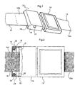
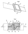
- FIG. 7 and 8 A embodiment of the indicating device according to the invention is shown in Figures 7 and 8 , in which parts and elements identical or corresponding to those of the preceding figures have been attributed the same reference numerals.
- a cylinder 20 extending transversely with respect to the strap 12 is again provided in this embodiment and is mounted in the casing 16 of the indicating device 10 so as to be rotatable about its own axis.
- the strap 12 is not divided into a first branch and a second branch but is formed as a continuous branch which extends through the casing 16, for example, extending along a pair of guide slots 18a and 18b, and engages with the cylinder 20 passing through a diametral slot 26 formed in the cylinder.
- a locking member 28 is advantageously provided to enable the device 10 to be fixed in a predetermined position along the strap 12 and is formed, for example, as a pin adapted to press the strap 12 against a surface of the guide slot 18a.
- the pin can be operated by the user by means of a slide 30.
- the operating principle is similar to that described with reference to the embodiment of Figures 5 and 6 .
- the cylinder 20 is held in a first angular position (shown in Figure 8 ) by the resilient force of a spring (not shown), as long as the force tensioning the strap 12 is below a predetermined value. Above this value, on the contrary, the cylinder 20 rotates about its own axis until it reaches a final angular position corresponding to the correct value of the force tensioning the strap.
- a slide 20 which extends transversely with respect to the strap 12 is again provided in this case and is mounted inside the casing 16 so as to be slidable in a perpendicular or inclined direction with respect to the plane of the strap 12.
- the strap 12 is formed as a continuous branch which extends through the casing 16 and is wrapped around a substantially semicylindrical upper surface of the slide 20.
- a pin-like locking member 28 is again provided in this case and can be operated by the user by means of a slide 30 to enable the device 10 to be fixed in a given position along the strap 12.
- the slide 20 which is subject to the resilient force of a spring 22, keeps the strap 12 clamped against an upper wall of the casing 16 (as shown in Figure 9 ) as long as the force tensioning the strap 12 is below a predetermined value. Above this value, on the contrary, the slide 20 is moved downwards until it reaches a final position which is indicative of the correct tensioning condition of the strap 12.
Claims (5)
- Dispositif indicateur (10) destiné à indiquer la tension correcte de la sangle de retenue (12) d'un dispositif de sécurité, en particulier d'un siège pour enfant de véhicule automobile, le dispositif comprenant :- un élément mobile (20) fonctionnant associé à la sangle (12) de façon à se déplacer vers une position donnée, qui est indicatrice de la condition de tension correcte, par suite de la force de traction exercée sur la sangle (12) ;- des moyens élastiques (22) destinés à exercer, sur l'élément mobile (20), une action opposée à celle exercée par la force de traction sur la sangle (12) de façon à empêcher l'élément mobile (20) d'atteindre ladite position tant que la force de traction exercée sur la sangle (12) est inférieure à une valeur prédéterminée donnée, et- des moyens d'affichage (24 ; G, R) destinés à fournir un signal indicateur de la condition de tension correcte de la sangle (12) quand l'élément mobile (20) est dans ladite position ;- un boîtier (16) à l'intérieur duquel l'élément mobile (20) est monté, ladite sangle de retenue (12) formant une branche continue s'étendant à travers ledit boîtier (16) ;caractérisé en ce que ledit élément mobile (20) est un cylindre, qui s'étend dans la direction transversale par rapport à ladite sangle (12), tourne autour de son propre axe vers ladite position à l'encontre de l'action desdits moyens élastiques, et comporte une fente diamétrale (26) dans laquelle pénètre ladite sangle de retenue (12).
- Dispositif selon la revendication 1, caractérisé en ce que ledit boîtier (16) comprend une paire de fentes de guidage (18a, 18b) placées sur des côtés opposés dudit élément mobile et dans lesquelles pénètre de manière coulissante ladite sangle de retenue (12).
- Dispositif selon la revendication 1 ou 2, caractérisé en ce qu'il comprend en outre un élément de blocage (28) pour fixer le dispositif (10) dans une position prédéterminée le long de ladite sangle de retenue (12).
- Dispositif selon les revendications 2 et 3, caractérisé en ce que ledit élément de blocage comprend un ergot (28) adapté pour presser ladite sangle de retenue (12) contre une surface d'une desdites fentes de guidage (18a).
- Dispositif selon l'une quelconque des revendications précédentes, caractérisé en ce que lesdits moyens d'affichage comprennent au moins une fenêtre (24) formée dans une paroi du boîtier (16) et au moins un symbole graphique (G) qui est indicateur de la condition de tension correcte de la sangle (12), et qui est prévu sur l'élément mobile (20) de manière à être visible à travers la fenêtre (24) quand l'élément mobile (20) est dans ladite position de tension correcte.
Applications Claiming Priority (2)
| Application Number | Priority Date | Filing Date | Title |
|---|---|---|---|
| IT000007A ITTO20040007A1 (it) | 2004-01-09 | 2004-01-09 | Dispositivo di segnalazione del corretto tensionamento di un nastro di ritenuta di un dispositivo di sicurezza. |
| ITTO20040007 | 2004-01-09 |
Publications (2)
| Publication Number | Publication Date |
|---|---|
| EP1552993A1 EP1552993A1 (fr) | 2005-07-13 |
| EP1552993B1 true EP1552993B1 (fr) | 2008-02-13 |
Family
ID=34587020
Family Applications (1)
| Application Number | Title | Priority Date | Filing Date |
|---|---|---|---|
| EP04425259A Expired - Lifetime EP1552993B1 (fr) | 2004-01-09 | 2004-04-08 | Dispositif pour indiquer une tension correcte d'une ceinture de sécurité |
Country Status (6)
| Country | Link |
|---|---|
| EP (1) | EP1552993B1 (fr) |
| AT (1) | ATE385932T1 (fr) |
| DE (1) | DE602004011747T2 (fr) |
| ES (1) | ES2300732T3 (fr) |
| IT (1) | ITTO20040007A1 (fr) |
| PT (1) | PT1552993E (fr) |
Cited By (2)
| Publication number | Priority date | Publication date | Assignee | Title |
|---|---|---|---|---|
| DE102010014167A1 (de) | 2010-03-19 | 2011-12-15 | Polycontact Ag | Gurtspannungsüberwachung |
| WO2021262649A1 (fr) * | 2020-06-26 | 2021-12-30 | Radio Systems Corporation | Collier pour animal de compagnie |
Families Citing this family (6)
| Publication number | Priority date | Publication date | Assignee | Title |
|---|---|---|---|---|
| GB0410185D0 (en) | 2004-05-07 | 2004-06-09 | Britax Excelsior | Tension indicator |
| DE102004036781B4 (de) * | 2004-07-29 | 2008-09-25 | Hs Products Engineering Gmbh | Kindersitz |
| FI126165B (en) * | 2013-06-11 | 2016-07-29 | Pulseon Oy | Strap for a portable heart rate monitor and portable heart rate monitor |
| AU2014224164B2 (en) * | 2013-09-13 | 2018-08-16 | Britax Childcare Pty Ltd | A belt tension indicator and a child restraint incorporating a belt tension indicator |
| US10897963B2 (en) | 2018-06-18 | 2021-01-26 | Indiana Mills & Manufacturing, Inc. | Tilt-lock adjuster with tension indicator |
| CN114801917A (zh) * | 2021-01-29 | 2022-07-29 | 宝钜瑞士股份有限公司 | 指示装置、安全带装置及儿童安全载具 |
Family Cites Families (6)
| Publication number | Priority date | Publication date | Assignee | Title |
|---|---|---|---|---|
| US5160186A (en) * | 1990-03-27 | 1992-11-03 | Indiana Mills And Manufacturing Inc. | Low profile web adjuster |
| US7862124B2 (en) * | 1998-08-18 | 2011-01-04 | Indiana Mills And Manufacturing, Inc. | Web adjuster and coupling |
| US6554318B2 (en) * | 2000-01-12 | 2003-04-29 | Delphi Technologies, Inc. | Seat belt tension sensor |
| US6400145B1 (en) * | 2000-05-04 | 2002-06-04 | Breed Automotive Technology, Inc. | Seat belt tension sensor, methods of integration and attachment |
| JP4592991B2 (ja) * | 2001-03-28 | 2010-12-08 | 古河電気工業株式会社 | シートベルト連結部材 |
| US6854415B2 (en) * | 2001-06-29 | 2005-02-15 | Finecard International Limited | Seat belt tension sensing device |
-
2004
- 2004-01-09 IT IT000007A patent/ITTO20040007A1/it unknown
- 2004-04-08 PT PT04425259T patent/PT1552993E/pt unknown
- 2004-04-08 DE DE602004011747T patent/DE602004011747T2/de not_active Expired - Lifetime
- 2004-04-08 EP EP04425259A patent/EP1552993B1/fr not_active Expired - Lifetime
- 2004-04-08 AT AT04425259T patent/ATE385932T1/de not_active IP Right Cessation
- 2004-04-08 ES ES04425259T patent/ES2300732T3/es not_active Expired - Lifetime
Cited By (2)
| Publication number | Priority date | Publication date | Assignee | Title |
|---|---|---|---|---|
| DE102010014167A1 (de) | 2010-03-19 | 2011-12-15 | Polycontact Ag | Gurtspannungsüberwachung |
| WO2021262649A1 (fr) * | 2020-06-26 | 2021-12-30 | Radio Systems Corporation | Collier pour animal de compagnie |
Also Published As
| Publication number | Publication date |
|---|---|
| DE602004011747T2 (de) | 2009-02-05 |
| ITTO20040007A1 (it) | 2004-04-09 |
| ATE385932T1 (de) | 2008-03-15 |
| EP1552993A1 (fr) | 2005-07-13 |
| DE602004011747D1 (de) | 2008-03-27 |
| PT1552993E (pt) | 2008-04-22 |
| ES2300732T3 (es) | 2008-06-16 |
Similar Documents
| Publication | Publication Date | Title |
|---|---|---|
| EP1723012B1 (fr) | Indication de la tension d'une sangle | |
| US20090025193A1 (en) | Belt Latch for a Safety Belt | |
| US5220713A (en) | Apparatus for use with a safety belt | |
| US4688849A (en) | Child passenger securing apparatus for use in vehicle | |
| US4757579A (en) | Buckle for child-restraining devices | |
| US7513530B2 (en) | Seatbelt apparatus | |
| US20080251002A1 (en) | Tension Indicator | |
| EP1552993B1 (fr) | Dispositif pour indiquer une tension correcte d'une ceinture de sécurité | |
| WO2012105762A2 (fr) | Languette de verrouillage de ceinture et ceinture de sécurité comprenant cette languette | |
| EP3156288B1 (fr) | Dispositif de retenue des occupants d'un véhicule | |
| US20060053903A1 (en) | Web tension indicator | |
| AU609896B2 (en) | A seat belt retractor | |
| US8382160B2 (en) | Belt latch for a safety belt | |
| JPH0214218B2 (fr) | ||
| US9096194B2 (en) | Seatbelt retractor | |
| CN112566815A (zh) | 具有张力指示器的倾斜锁定调节器 | |
| WO2012105761A2 (fr) | Languette de verrouillage de ceinture et ceinture de sécurité comprenant cette languette | |
| US6416003B1 (en) | Belt reel for a belt retractor of a vehicle occupant restraint system | |
| KR101148166B1 (ko) | 차량용 안전벨트의 버클 홀스위치 | |
| EP1896302B1 (fr) | Indicateur de tension de courroie | |
| EP0063086A1 (fr) | Agencement de ceinture de sécurité | |
| WO2018056084A1 (fr) | Languette et dispositif de ceinture de sécurité | |
| KR0114527Y1 (ko) | 시트벨트 압박감 완화장치가 내설된 자동차의 리트랙터 | |
| KR200322237Y1 (ko) | 차량용 시트벨트의 자동 해제장치 | |
| KR200213499Y1 (ko) | 어린이용 안전밸트가 구비된 차량용 시트 |
Legal Events
| Date | Code | Title | Description |
|---|---|---|---|
| PUAI | Public reference made under article 153(3) epc to a published international application that has entered the european phase |
Free format text: ORIGINAL CODE: 0009012 |
|
| AK | Designated contracting states |
Kind code of ref document: A1 Designated state(s): AT BE BG CH CY CZ DE DK EE ES FI FR GB GR HU IE IT LI LU MC NL PL PT RO SE SI SK TR |
|
| AX | Request for extension of the european patent |
Extension state: AL HR LT LV MK |
|
| 17P | Request for examination filed |
Effective date: 20060111 |
|
| AKX | Designation fees paid |
Designated state(s): AT BE BG CH CY CZ DE DK EE ES FI FR GB GR HU IE IT LI LU MC NL PL PT RO SE SI SK TR |
|
| 17Q | First examination report despatched |
Effective date: 20061117 |
|
| GRAP | Despatch of communication of intention to grant a patent |
Free format text: ORIGINAL CODE: EPIDOSNIGR1 |
|
| GRAS | Grant fee paid |
Free format text: ORIGINAL CODE: EPIDOSNIGR3 |
|
| GRAA | (expected) grant |
Free format text: ORIGINAL CODE: 0009210 |
|
| AK | Designated contracting states |
Kind code of ref document: B1 Designated state(s): AT BE BG CH CY CZ DE DK EE ES FI FR GB GR HU IE IT LI LU MC NL PL PT RO SE SI SK TR |
|
| REG | Reference to a national code |
Ref country code: GB Ref legal event code: FG4D |
|
| REG | Reference to a national code |
Ref country code: CH Ref legal event code: EP |
|
| REG | Reference to a national code |
Ref country code: IE Ref legal event code: FG4D |
|
| REF | Corresponds to: |
Ref document number: 602004011747 Country of ref document: DE Date of ref document: 20080327 Kind code of ref document: P |
|
| REG | Reference to a national code |
Ref country code: PT Ref legal event code: SC4A Free format text: AVAILABILITY OF NATIONAL TRANSLATION Effective date: 20080410 |
|
| REG | Reference to a national code |
Ref country code: ES Ref legal event code: FG2A Ref document number: 2300732 Country of ref document: ES Kind code of ref document: T3 |
|
| PG25 | Lapsed in a contracting state [announced via postgrant information from national office to epo] |
Ref country code: FI Free format text: LAPSE BECAUSE OF FAILURE TO SUBMIT A TRANSLATION OF THE DESCRIPTION OR TO PAY THE FEE WITHIN THE PRESCRIBED TIME-LIMIT Effective date: 20080213 |
|
| PG25 | Lapsed in a contracting state [announced via postgrant information from national office to epo] |
Ref country code: AT Free format text: LAPSE BECAUSE OF FAILURE TO SUBMIT A TRANSLATION OF THE DESCRIPTION OR TO PAY THE FEE WITHIN THE PRESCRIBED TIME-LIMIT Effective date: 20080213 |
|
| ET | Fr: translation filed | ||
| PG25 | Lapsed in a contracting state [announced via postgrant information from national office to epo] |
Ref country code: BE Free format text: LAPSE BECAUSE OF FAILURE TO SUBMIT A TRANSLATION OF THE DESCRIPTION OR TO PAY THE FEE WITHIN THE PRESCRIBED TIME-LIMIT Effective date: 20080213 Ref country code: PL Free format text: LAPSE BECAUSE OF FAILURE TO SUBMIT A TRANSLATION OF THE DESCRIPTION OR TO PAY THE FEE WITHIN THE PRESCRIBED TIME-LIMIT Effective date: 20080213 Ref country code: SI Free format text: LAPSE BECAUSE OF FAILURE TO SUBMIT A TRANSLATION OF THE DESCRIPTION OR TO PAY THE FEE WITHIN THE PRESCRIBED TIME-LIMIT Effective date: 20080213 |
|
| PG25 | Lapsed in a contracting state [announced via postgrant information from national office to epo] |
Ref country code: SE Free format text: LAPSE BECAUSE OF FAILURE TO SUBMIT A TRANSLATION OF THE DESCRIPTION OR TO PAY THE FEE WITHIN THE PRESCRIBED TIME-LIMIT Effective date: 20080513 Ref country code: SK Free format text: LAPSE BECAUSE OF FAILURE TO SUBMIT A TRANSLATION OF THE DESCRIPTION OR TO PAY THE FEE WITHIN THE PRESCRIBED TIME-LIMIT Effective date: 20080213 Ref country code: CZ Free format text: LAPSE BECAUSE OF FAILURE TO SUBMIT A TRANSLATION OF THE DESCRIPTION OR TO PAY THE FEE WITHIN THE PRESCRIBED TIME-LIMIT Effective date: 20080213 Ref country code: DK Free format text: LAPSE BECAUSE OF FAILURE TO SUBMIT A TRANSLATION OF THE DESCRIPTION OR TO PAY THE FEE WITHIN THE PRESCRIBED TIME-LIMIT Effective date: 20080213 |
|
| PG25 | Lapsed in a contracting state [announced via postgrant information from national office to epo] |
Ref country code: MC Free format text: LAPSE BECAUSE OF NON-PAYMENT OF DUE FEES Effective date: 20080430 Ref country code: RO Free format text: LAPSE BECAUSE OF FAILURE TO SUBMIT A TRANSLATION OF THE DESCRIPTION OR TO PAY THE FEE WITHIN THE PRESCRIBED TIME-LIMIT Effective date: 20080213 |
|
| REG | Reference to a national code |
Ref country code: CH Ref legal event code: PL |
|
| PLBE | No opposition filed within time limit |
Free format text: ORIGINAL CODE: 0009261 |
|
| STAA | Information on the status of an ep patent application or granted ep patent |
Free format text: STATUS: NO OPPOSITION FILED WITHIN TIME LIMIT |
|
| 26N | No opposition filed |
Effective date: 20081114 |
|
| PG25 | Lapsed in a contracting state [announced via postgrant information from national office to epo] |
Ref country code: EE Free format text: LAPSE BECAUSE OF FAILURE TO SUBMIT A TRANSLATION OF THE DESCRIPTION OR TO PAY THE FEE WITHIN THE PRESCRIBED TIME-LIMIT Effective date: 20080213 Ref country code: LI Free format text: LAPSE BECAUSE OF NON-PAYMENT OF DUE FEES Effective date: 20080430 Ref country code: CH Free format text: LAPSE BECAUSE OF NON-PAYMENT OF DUE FEES Effective date: 20080430 |
|
| PG25 | Lapsed in a contracting state [announced via postgrant information from national office to epo] |
Ref country code: IE Free format text: LAPSE BECAUSE OF NON-PAYMENT OF DUE FEES Effective date: 20080408 Ref country code: BG Free format text: LAPSE BECAUSE OF FAILURE TO SUBMIT A TRANSLATION OF THE DESCRIPTION OR TO PAY THE FEE WITHIN THE PRESCRIBED TIME-LIMIT Effective date: 20080513 |
|
| PG25 | Lapsed in a contracting state [announced via postgrant information from national office to epo] |
Ref country code: CY Free format text: LAPSE BECAUSE OF FAILURE TO SUBMIT A TRANSLATION OF THE DESCRIPTION OR TO PAY THE FEE WITHIN THE PRESCRIBED TIME-LIMIT Effective date: 20080213 |
|
| PG25 | Lapsed in a contracting state [announced via postgrant information from national office to epo] |
Ref country code: IT Free format text: LAPSE BECAUSE OF NON-PAYMENT OF DUE FEES Effective date: 20080408 |
|
| PG25 | Lapsed in a contracting state [announced via postgrant information from national office to epo] |
Ref country code: HU Free format text: LAPSE BECAUSE OF FAILURE TO SUBMIT A TRANSLATION OF THE DESCRIPTION OR TO PAY THE FEE WITHIN THE PRESCRIBED TIME-LIMIT Effective date: 20080814 Ref country code: LU Free format text: LAPSE BECAUSE OF NON-PAYMENT OF DUE FEES Effective date: 20080408 |
|
| PG25 | Lapsed in a contracting state [announced via postgrant information from national office to epo] |
Ref country code: TR Free format text: LAPSE BECAUSE OF FAILURE TO SUBMIT A TRANSLATION OF THE DESCRIPTION OR TO PAY THE FEE WITHIN THE PRESCRIBED TIME-LIMIT Effective date: 20080213 |
|
| PG25 | Lapsed in a contracting state [announced via postgrant information from national office to epo] |
Ref country code: GR Free format text: LAPSE BECAUSE OF FAILURE TO SUBMIT A TRANSLATION OF THE DESCRIPTION OR TO PAY THE FEE WITHIN THE PRESCRIBED TIME-LIMIT Effective date: 20080514 |
|
| PGRI | Patent reinstated in contracting state [announced from national office to epo] |
Ref country code: IT Effective date: 20110616 |
|
| REG | Reference to a national code |
Ref country code: FR Ref legal event code: PLFP Year of fee payment: 13 |
|
| REG | Reference to a national code |
Ref country code: FR Ref legal event code: PLFP Year of fee payment: 14 |
|
| REG | Reference to a national code |
Ref country code: FR Ref legal event code: PLFP Year of fee payment: 15 |
|
| PGFP | Annual fee paid to national office [announced via postgrant information from national office to epo] |
Ref country code: NL Payment date: 20190426 Year of fee payment: 16 |
|
| PGFP | Annual fee paid to national office [announced via postgrant information from national office to epo] |
Ref country code: PT Payment date: 20190401 Year of fee payment: 16 Ref country code: DE Payment date: 20190531 Year of fee payment: 16 Ref country code: IT Payment date: 20190401 Year of fee payment: 16 Ref country code: ES Payment date: 20190524 Year of fee payment: 16 |
|
| PGFP | Annual fee paid to national office [announced via postgrant information from national office to epo] |
Ref country code: FR Payment date: 20190426 Year of fee payment: 16 |
|
| PGFP | Annual fee paid to national office [announced via postgrant information from national office to epo] |
Ref country code: GB Payment date: 20190429 Year of fee payment: 16 |
|
| REG | Reference to a national code |
Ref country code: DE Ref legal event code: R119 Ref document number: 602004011747 Country of ref document: DE |
|
| REG | Reference to a national code |
Ref country code: NL Ref legal event code: MM Effective date: 20200501 |
|
| PG25 | Lapsed in a contracting state [announced via postgrant information from national office to epo] |
Ref country code: DE Free format text: LAPSE BECAUSE OF NON-PAYMENT OF DUE FEES Effective date: 20201103 Ref country code: PT Free format text: LAPSE BECAUSE OF NON-PAYMENT OF DUE FEES Effective date: 20201008 Ref country code: FR Free format text: LAPSE BECAUSE OF NON-PAYMENT OF DUE FEES Effective date: 20200430 |
|
| GBPC | Gb: european patent ceased through non-payment of renewal fee |
Effective date: 20200408 |
|
| PG25 | Lapsed in a contracting state [announced via postgrant information from national office to epo] |
Ref country code: NL Free format text: LAPSE BECAUSE OF NON-PAYMENT OF DUE FEES Effective date: 20200501 |
|
| PG25 | Lapsed in a contracting state [announced via postgrant information from national office to epo] |
Ref country code: GB Free format text: LAPSE BECAUSE OF NON-PAYMENT OF DUE FEES Effective date: 20200408 |
|
| REG | Reference to a national code |
Ref country code: ES Ref legal event code: FD2A Effective date: 20210831 |
|
| PG25 | Lapsed in a contracting state [announced via postgrant information from national office to epo] |
Ref country code: ES Free format text: LAPSE BECAUSE OF NON-PAYMENT OF DUE FEES Effective date: 20200409 |
|
| PG25 | Lapsed in a contracting state [announced via postgrant information from national office to epo] |
Ref country code: IT Free format text: LAPSE BECAUSE OF NON-PAYMENT OF DUE FEES Effective date: 20200408 |