EP1552802B1 - Procede de realisation d'element de presentation - Google Patents
Procede de realisation d'element de presentation Download PDFInfo
- Publication number
- EP1552802B1 EP1552802B1 EP03788011A EP03788011A EP1552802B1 EP 1552802 B1 EP1552802 B1 EP 1552802B1 EP 03788011 A EP03788011 A EP 03788011A EP 03788011 A EP03788011 A EP 03788011A EP 1552802 B1 EP1552802 B1 EP 1552802B1
- Authority
- EP
- European Patent Office
- Prior art keywords
- web
- machine direction
- layer web
- outer layer
- nonwoven fabric
- Prior art date
- Legal status (The legal status is an assumption and is not a legal conclusion. Google has not performed a legal analysis and makes no representation as to the accuracy of the status listed.)
- Expired - Lifetime
Links
- 238000000034 method Methods 0.000 title claims description 54
- 239000004745 nonwoven fabric Substances 0.000 claims description 71
- 238000005304 joining Methods 0.000 claims description 28
- 238000005520 cutting process Methods 0.000 claims description 26
- 239000002250 absorbent Substances 0.000 claims description 23
- 230000002209 hydrophobic effect Effects 0.000 claims description 22
- 239000002985 plastic film Substances 0.000 claims description 18
- 229920006255 plastic film Polymers 0.000 claims description 18
- 239000002131 composite material Substances 0.000 claims description 5
- 239000004831 Hot glue Substances 0.000 description 21
- 239000000853 adhesive Substances 0.000 description 10
- 230000001070 adhesive effect Effects 0.000 description 10
- 230000002745 absorbent Effects 0.000 description 8
- 239000000835 fiber Substances 0.000 description 4
- 238000004519 manufacturing process Methods 0.000 description 4
- 239000000463 material Substances 0.000 description 4
- 238000007789 sealing Methods 0.000 description 4
- 239000002245 particle Substances 0.000 description 3
- 229920000642 polymer Polymers 0.000 description 3
- 235000013580 sausages Nutrition 0.000 description 3
- 239000004698 Polyethylene Substances 0.000 description 2
- 239000000203 mixture Substances 0.000 description 2
- -1 polyethylene Polymers 0.000 description 2
- 229920000573 polyethylene Polymers 0.000 description 2
- 229920003002 synthetic resin Polymers 0.000 description 2
- 239000000057 synthetic resin Substances 0.000 description 2
- 229920001169 thermoplastic Polymers 0.000 description 2
- 239000004416 thermosoftening plastic Substances 0.000 description 2
- 239000004743 Polypropylene Substances 0.000 description 1
- 239000007788 liquid Substances 0.000 description 1
- 229920002647 polyamide Polymers 0.000 description 1
- 229920000728 polyester Polymers 0.000 description 1
- 229920006149 polyester-amide block copolymer Polymers 0.000 description 1
- 229920000098 polyolefin Polymers 0.000 description 1
- 229920001155 polypropylene Polymers 0.000 description 1
- 239000000126 substance Substances 0.000 description 1
Images


Classifications
-
- A—HUMAN NECESSITIES
- A61—MEDICAL OR VETERINARY SCIENCE; HYGIENE
- A61F—FILTERS IMPLANTABLE INTO BLOOD VESSELS; PROSTHESES; DEVICES PROVIDING PATENCY TO, OR PREVENTING COLLAPSING OF, TUBULAR STRUCTURES OF THE BODY, e.g. STENTS; ORTHOPAEDIC, NURSING OR CONTRACEPTIVE DEVICES; FOMENTATION; TREATMENT OR PROTECTION OF EYES OR EARS; BANDAGES, DRESSINGS OR ABSORBENT PADS; FIRST-AID KITS
- A61F13/00—Bandages or dressings; Absorbent pads
- A61F13/15—Absorbent pads, e.g. sanitary towels, swabs or tampons for external or internal application to the body; Supporting or fastening means therefor; Tampon applicators
- A61F13/15577—Apparatus or processes for manufacturing
- A61F13/15699—Forming webs by bringing together several webs, e.g. by laminating or folding several webs, with or without additional treatment of the webs
-
- A—HUMAN NECESSITIES
- A61—MEDICAL OR VETERINARY SCIENCE; HYGIENE
- A61F—FILTERS IMPLANTABLE INTO BLOOD VESSELS; PROSTHESES; DEVICES PROVIDING PATENCY TO, OR PREVENTING COLLAPSING OF, TUBULAR STRUCTURES OF THE BODY, e.g. STENTS; ORTHOPAEDIC, NURSING OR CONTRACEPTIVE DEVICES; FOMENTATION; TREATMENT OR PROTECTION OF EYES OR EARS; BANDAGES, DRESSINGS OR ABSORBENT PADS; FIRST-AID KITS
- A61F13/00—Bandages or dressings; Absorbent pads
- A61F13/15—Absorbent pads, e.g. sanitary towels, swabs or tampons for external or internal application to the body; Supporting or fastening means therefor; Tampon applicators
- A61F13/15577—Apparatus or processes for manufacturing
- A61F13/15585—Apparatus or processes for manufacturing of babies' napkins, e.g. diapers
- A61F13/15593—Apparatus or processes for manufacturing of babies' napkins, e.g. diapers having elastic ribbons fixed thereto; Devices for applying the ribbons
-
- A—HUMAN NECESSITIES
- A61—MEDICAL OR VETERINARY SCIENCE; HYGIENE
- A61F—FILTERS IMPLANTABLE INTO BLOOD VESSELS; PROSTHESES; DEVICES PROVIDING PATENCY TO, OR PREVENTING COLLAPSING OF, TUBULAR STRUCTURES OF THE BODY, e.g. STENTS; ORTHOPAEDIC, NURSING OR CONTRACEPTIVE DEVICES; FOMENTATION; TREATMENT OR PROTECTION OF EYES OR EARS; BANDAGES, DRESSINGS OR ABSORBENT PADS; FIRST-AID KITS
- A61F13/00—Bandages or dressings; Absorbent pads
- A61F13/15—Absorbent pads, e.g. sanitary towels, swabs or tampons for external or internal application to the body; Supporting or fastening means therefor; Tampon applicators
- A61F13/15577—Apparatus or processes for manufacturing
- A61F13/15617—Making absorbent pads from fibres or pulverulent material with or without treatment of the fibres
- A61F13/15634—Making fibrous pads between sheets or webs
-
- A—HUMAN NECESSITIES
- A61—MEDICAL OR VETERINARY SCIENCE; HYGIENE
- A61F—FILTERS IMPLANTABLE INTO BLOOD VESSELS; PROSTHESES; DEVICES PROVIDING PATENCY TO, OR PREVENTING COLLAPSING OF, TUBULAR STRUCTURES OF THE BODY, e.g. STENTS; ORTHOPAEDIC, NURSING OR CONTRACEPTIVE DEVICES; FOMENTATION; TREATMENT OR PROTECTION OF EYES OR EARS; BANDAGES, DRESSINGS OR ABSORBENT PADS; FIRST-AID KITS
- A61F13/00—Bandages or dressings; Absorbent pads
- A61F13/15—Absorbent pads, e.g. sanitary towels, swabs or tampons for external or internal application to the body; Supporting or fastening means therefor; Tampon applicators
- A61F13/15577—Apparatus or processes for manufacturing
- A61F13/15707—Mechanical treatment, e.g. notching, twisting, compressing, shaping
- A61F13/15723—Partitioning batts; Cutting
-
- A—HUMAN NECESSITIES
- A61—MEDICAL OR VETERINARY SCIENCE; HYGIENE
- A61F—FILTERS IMPLANTABLE INTO BLOOD VESSELS; PROSTHESES; DEVICES PROVIDING PATENCY TO, OR PREVENTING COLLAPSING OF, TUBULAR STRUCTURES OF THE BODY, e.g. STENTS; ORTHOPAEDIC, NURSING OR CONTRACEPTIVE DEVICES; FOMENTATION; TREATMENT OR PROTECTION OF EYES OR EARS; BANDAGES, DRESSINGS OR ABSORBENT PADS; FIRST-AID KITS
- A61F13/00—Bandages or dressings; Absorbent pads
- A61F13/15—Absorbent pads, e.g. sanitary towels, swabs or tampons for external or internal application to the body; Supporting or fastening means therefor; Tampon applicators
- A61F13/15577—Apparatus or processes for manufacturing
- A61F13/15804—Plant, e.g. involving several steps
-
- A—HUMAN NECESSITIES
- A61—MEDICAL OR VETERINARY SCIENCE; HYGIENE
- A61F—FILTERS IMPLANTABLE INTO BLOOD VESSELS; PROSTHESES; DEVICES PROVIDING PATENCY TO, OR PREVENTING COLLAPSING OF, TUBULAR STRUCTURES OF THE BODY, e.g. STENTS; ORTHOPAEDIC, NURSING OR CONTRACEPTIVE DEVICES; FOMENTATION; TREATMENT OR PROTECTION OF EYES OR EARS; BANDAGES, DRESSINGS OR ABSORBENT PADS; FIRST-AID KITS
- A61F13/00—Bandages or dressings; Absorbent pads
- A61F13/15—Absorbent pads, e.g. sanitary towels, swabs or tampons for external or internal application to the body; Supporting or fastening means therefor; Tampon applicators
- A61F13/45—Absorbent pads, e.g. sanitary towels, swabs or tampons for external or internal application to the body; Supporting or fastening means therefor; Tampon applicators characterised by the shape
- A61F13/49—Absorbent pads, e.g. sanitary towels, swabs or tampons for external or internal application to the body; Supporting or fastening means therefor; Tampon applicators characterised by the shape specially adapted to be worn around the waist, e.g. diapers, nappies
- A61F13/496—Absorbent pads, e.g. sanitary towels, swabs or tampons for external or internal application to the body; Supporting or fastening means therefor; Tampon applicators characterised by the shape specially adapted to be worn around the waist, e.g. diapers, nappies in the form of pants or briefs
-
- A—HUMAN NECESSITIES
- A61—MEDICAL OR VETERINARY SCIENCE; HYGIENE
- A61F—FILTERS IMPLANTABLE INTO BLOOD VESSELS; PROSTHESES; DEVICES PROVIDING PATENCY TO, OR PREVENTING COLLAPSING OF, TUBULAR STRUCTURES OF THE BODY, e.g. STENTS; ORTHOPAEDIC, NURSING OR CONTRACEPTIVE DEVICES; FOMENTATION; TREATMENT OR PROTECTION OF EYES OR EARS; BANDAGES, DRESSINGS OR ABSORBENT PADS; FIRST-AID KITS
- A61F13/00—Bandages or dressings; Absorbent pads
- A61F13/15—Absorbent pads, e.g. sanitary towels, swabs or tampons for external or internal application to the body; Supporting or fastening means therefor; Tampon applicators
- A61F13/84—Accessories, not otherwise provided for, for absorbent pads
- A61F2013/8497—Accessories, not otherwise provided for, for absorbent pads having decorations or indicia means
-
- Y—GENERAL TAGGING OF NEW TECHNOLOGICAL DEVELOPMENTS; GENERAL TAGGING OF CROSS-SECTIONAL TECHNOLOGIES SPANNING OVER SEVERAL SECTIONS OF THE IPC; TECHNICAL SUBJECTS COVERED BY FORMER USPC CROSS-REFERENCE ART COLLECTIONS [XRACs] AND DIGESTS
- Y10—TECHNICAL SUBJECTS COVERED BY FORMER USPC
- Y10T—TECHNICAL SUBJECTS COVERED BY FORMER US CLASSIFICATION
- Y10T156/00—Adhesive bonding and miscellaneous chemical manufacture
- Y10T156/10—Methods of surface bonding and/or assembly therefor
- Y10T156/1052—Methods of surface bonding and/or assembly therefor with cutting, punching, tearing or severing
- Y10T156/1084—Methods of surface bonding and/or assembly therefor with cutting, punching, tearing or severing of continuous or running length bonded web
-
- Y—GENERAL TAGGING OF NEW TECHNOLOGICAL DEVELOPMENTS; GENERAL TAGGING OF CROSS-SECTIONAL TECHNOLOGIES SPANNING OVER SEVERAL SECTIONS OF THE IPC; TECHNICAL SUBJECTS COVERED BY FORMER USPC CROSS-REFERENCE ART COLLECTIONS [XRACs] AND DIGESTS
- Y10—TECHNICAL SUBJECTS COVERED BY FORMER USPC
- Y10T—TECHNICAL SUBJECTS COVERED BY FORMER US CLASSIFICATION
- Y10T156/00—Adhesive bonding and miscellaneous chemical manufacture
- Y10T156/10—Methods of surface bonding and/or assembly therefor
- Y10T156/1089—Methods of surface bonding and/or assembly therefor of discrete laminae to single face of additional lamina
- Y10T156/1092—All laminae planar and face to face
- Y10T156/1093—All laminae planar and face to face with covering of discrete laminae with additional lamina
- Y10T156/1095—Opposed laminae are running length webs
-
- Y—GENERAL TAGGING OF NEW TECHNOLOGICAL DEVELOPMENTS; GENERAL TAGGING OF CROSS-SECTIONAL TECHNOLOGIES SPANNING OVER SEVERAL SECTIONS OF THE IPC; TECHNICAL SUBJECTS COVERED BY FORMER USPC CROSS-REFERENCE ART COLLECTIONS [XRACs] AND DIGESTS
- Y10—TECHNICAL SUBJECTS COVERED BY FORMER USPC
- Y10T—TECHNICAL SUBJECTS COVERED BY FORMER US CLASSIFICATION
- Y10T156/00—Adhesive bonding and miscellaneous chemical manufacture
- Y10T156/10—Methods of surface bonding and/or assembly therefor
- Y10T156/1089—Methods of surface bonding and/or assembly therefor of discrete laminae to single face of additional lamina
- Y10T156/1092—All laminae planar and face to face
- Y10T156/1097—Lamina is running length web
Definitions
- This invention relates to a process for attaching, in front and rear waist regions of a disposable garment such as a diaper comprising an outer sheet and a liquid-absorbent inner panel attached to the outer sheet, indicator elements which are visually recognizable from the exterior of the garment.
- WO 9827906 discloses methods for making absorbent articles with separate leg cuffs and waist pieces, including applying selected material to an absorbent article web sausage. More particularly, the methods include cutting a waist opening in the web sausage and applying a waist piece to cover the waist opening. The methods further include cutting leg cut-outs on each side of the web sausage and applying leg cuffs to cover the leg cut-outs.
- JP 2001054536 discloses a disposable diaper formed in such a manner that a pattern can be imparted only to the portion of the diaper at a low cost even when the patterns of, for example, multicolor printing is used.
- the pattern is printed on a sheet of a square shape which is affixed to the inner side of one exterior sheet of the diaper. This pattern sheet is made visible through the external sheet.
- a method for manufacturing an absorbent article comprising the steps of continuously feeding out a long, extensible, continuous member from a predetermined position, cutting the continuous member into lengths each equivalent to a length of one sheet of the absorbent article at a predetermined position, and fixedly arranging the cut continuous member at a predetermined position of the absorbent article, wherein a predetermined pattern is preliminarily printed on the continuous member at a printing pitch shorter than the cutting length of the continuous member, and the speed for feeding out is controlled such that the predetermined pattern is located at a predetermined part of the cut continuous member, thereby obtaining the absorbent article in which the predetermined pattern is arranged at a predetermined position.
- WO 0045767 discloses a process and apparatus for registering a plurality of discrete components to a continuously moving first layer of material which produces a disposable absorbent garment with improved alignment of the components on the first layer of material.
- the first layer has a plurality of reference marks positioned thereon.
- Various devices are used to compare distances between the reference marks to distances between corresponding components and synchronize a feed rate of the components to a feed rate of the first layer. After adhering the components to the first layer, the positions of the components relative to the reference marks are once again checked and, if necessary, the set point for the feed rate of the components is adjusted.
- Japanese Patent Application Publication No. 2001-54536A discloses a pull-on disposable article including a patterned sheet and a process for making the same.
- This diaper comprises a liquid-impervious backsheet lying on the side facing away from a wearer's body (outer layer web), a liquid-pervious topsheet (inner layer web) lying on the side facing the wearer's body, and a liquid-absorbent core interposed between these sheets.
- This article has a front waist region, a rear waist region, a crotch region extending between these waist regions, a waist-opening and a pair of leg-openings.
- the patterned sheet adapted to be visually recognizable from the exterior of the article is attached to an inner surface of the outer sheet.
- the process for making this diaper comprises a step of attaching the patterned sheet in which the patterned sheet having an area smaller than the outer sheet is attached to the inner surface of the outer sheet at a predetermined location, a step of securing the core in which the core is secured to the inner surface of the outer sheet and a step of joining the sheets in which the inner sheet is placed upon and joined with the upper surface of the core.
- a plurality of the patterned sheets are successively fed onto the inner surface of the outer sheet so as to be spaced one from another by a predetermined dimension in a longitudinal direction of the outer sheet and then these patterned sheets are attached to the outer sheet by means of a hot melt adhesive.
- a plurality of the patterned sheets must be individually fed onto and attached to the inner surface of the outer sheet with each pair of the patterned sheets being spaced apart from each other by a predetermined dimension in a transverse dimension. Feeding and attaching of these patterned sheets inevitably doubles time and labor and require the additional device as well as steps associated with such feeding as well as such attaching. Consequently, it is impossible to manufacture the diapers at a low cost.
- a process for attaching, in front and rear regions of a disposable garment (1A) which comprises an outer sheet and a liquid-absorbent inner panel attached to said outer sheet, indicator elements which are visually recognizable from an exterior of said garment said process is characterized by the steps of:
- the improvement according to the present invention is characterized in that the process comprising the steps of: feeding a plurality of liquid-absorbent cores each having front and rear end zones and an intermediate zone and running in a machine direction onto an inner surface of one of a continuous first outer layer web and a continuous inner layer web running in the machine direction, while feeding a plurality of indication sheets each extending in said machine direction and having said indicator elements in front and rear halves thereof, respectively, at regular intervals in said machine direction onto an outer surface of said first outer layer web; placing said intermediate zone of said core between each pair of said indication sheets adjacent to each other in said machine direction so that said rear half of a front one of said indication sheets adjacent to each other in said machine direction is placed upon said front end zone of said core, and said front half of a rear one of said indication sheets adjacent to each other in said machine direction (X) is placed upon said rear end zone of said core; joining said indication sheet to said first outer layer web, joining said core to at least one of said inner layer web and said first outer layer web, and joining inner surfaces of
- Fig. 1 is a partially cut away perspective view showing a wearing article 1A made by a process for attaching the indicator element as will be described later and Fig. 2 is an exploded perspective view showing the article 1A of Fig. 1 .
- a waist-surrounding direction is indicated by an arrow L
- a longitudinal direction is indicated by an arrow M
- a leg-surrounding direction is indicated by an arrow N (in Fig. 1 alone).
- Inner surfaces of a fibrous nonwoven fabric layer U1 forming an outer sheet 2, fibrous nonwoven fabric layers U2, U3 forming an inner panel 3, a plastic film F2 and an indication sheet 13 refers to surfaces thereof facing a liquid-absorbent core C and expression “outer surfaces” thereof refers to surfaces facing away from the core C.
- the article 1A is of pants-type and disposable after use.
- the article 1A comprises a substantially liquid-impervious outer sheet 2 and a liquid-absorbent inner panel 3 attached to the inner side of the outer sheet 2.
- the article 1A is composed of front and rear waist regions 4, 6 and a crotch region 5 extending between these waist regions 4; 6.
- the article 1A has a waist-surrounding upper end zone 7 extending in the front and rear waist regions 4, 6 in the waist-surrounding direction, transversely opposite waist's lateral zones 8 extending in the front and rear waist regions 4, 6 in the longitudinal direction and transversely opposite legs' lateral zones 9 extending in the crotch region 5 in the leg-surrounding direction.
- the legs' lateral zones 9 describe circular arcs which are convex inwardly of the article 1A as viewed in the waist-surrounding direction.
- the article 1A has a generally hourglass-like planar shape when the article 1A is developed.
- the waist's lateral zones 8 are overlaid and joined together by means of plural heat-sealing lines 10 arranged intermittently in the longitudinal direction.
- the article 1A has a waist-hole 11 and a pair of leg-holes 12 below the waist-hole 11.
- the front and rear waist regions 4, 6 are provided in respective transversely middle zones thereof with an indication sheet 13 having indicator elements 14 adapted to be visually recognized from an exterior of the article 1A.
- Each of the indicator elements 14 comprises an illustration of a bear' s face printed on the indication sheet 13.
- the indicator element 14 is not limited to such an illustration but may be in the form of pattern, letters or figures.
- the front waist region 4 is provided in its transversely middle zone with the indication sheet 13 printed with an illustration while the rear waist region 6 is provided in its transversely middle zone with the indication sheet 13 printed with letters. It is also possible to provide the front waist region 4 in its transversely middle zone with the indication sheet 13 printed with an illustration of a bear' s face and to provide the rear waist region 6 in its transversely middle zone with the indication sheet 13 printed with an illustration of a horse' face.
- the outer sheet 2 is formed by the moisture-permeable but hydrophobic fibrous nonwoven fabric U1.
- the indication sheet 13 is formed by a moisture-permeable but liquid-impervious plastic film F1. Alternatively, the indication sheet 13 may be formed by a moisture-permeable but hydrophobic fibrous nonwoven fabric.
- the waist-surrounding upper end zone 7 is provided with a band-like waist elastic member 16 (second stretchable elastic member) extending in the waist-surrounding direction attached thereto so as to be contractible.
- the elastic member 16 comprises band-like non-woven fabric layers and a plurality of stretchable elastic members which are wrapped up in and secured to the non-woven fabric layer in a stretched state and is attached to the inner surface of the outer sheet 2.
- the panel 3 has a generally rectangular shape and extends over the crotch region 5 into the front and rear waist regions 4, 6.
- the panel 3 is formed by the moisture-permeable but hydrophobic fibrous nonwoven fabric layer U2 (first outer layer web) lying on a side facing away from a wearer's body, the moisture-permeable but liquid-impervious plastic film F2 (second outer layer web), the moisture-permeable and hydrophilic fibrous nonwoven fabric layer U3 (inner layer web) lying on a side facing the wearer's body and a liquid-absorbent core C interposed between these nonwoven fabric layers U2, U3 (See Fig. 2 ).
- the panel 3 has longitudinally opposite end zones 17 extending in the waist-surrounding direction and transversely opposite side edge zones 18 extending in the longitudinal direction. Portions of the nonwoven fabric layers U2, U3 extending outward beyond a periphery of the core C have respective inner surfaces overlaid and joined together.
- a plurality of leg elastic members 19 are attached to the side edge zones 18 of the panel 3 so that these elastic members 19 may extend in the longitudinal direction and be contractible in this direction.
- the leg elastic members 19 are interposed between the nonwoven fabric layers U2, U3 and secured to inner surfaces of these nonwoven fabric layers U2, U3.
- the leg elastic members 19 may be interposed between the nonwoven fabric layer U2 and the film F2 and secured to the inner and outer surfaces of these layer U2 and film F2.
- the panel 3 is attached to the inner surface of the outer sheet 2 by securing an outer surface of the film F2 to the inner surface of the outer sheet 2 by means of a hot melt adhesive (not shown).
- the nonwoven fabric layer U2 and the film F2 respectively have their areas slightly larger than that of a lower surface of the core C and cover an entire lower surface of the core C.
- the nonwoven fabric layer U3 has its area slightly larger than that of an upper surface of the core C and covers the entire upper surface of the core C.
- the nonwoven fabric layer U2 has its inner surface secured to the lower surface of the core C by means of a hot melt adhesive (not shown).
- the nonwoven fabric U2 and the film F2 respectively have their outer and inner surfaces joined together by means of a hot melt adhesive (not shown).
- the nonwoven fabric layer U3 has its inner surface secured to the upper surface of the core C by means of a hot melt adhesive (not shown).
- the indication sheet 13 is interposed between the nonwoven fabric layer U2 and the film F2 and has its inner surface joined to an outer surface of the nonwoven fabric layer U2 by means of a hot melt adhesive (not shown).
- the film F2 and the indication sheet 13 are left free from each other.
- the core C comprises a mixture of fluff pulp and super-absorbent polymer particles or a mixture of fluff pulp, super-absorbent polymer particles and thermoplastic synthetic resin fibers, in any case, compressed to a desired thickness.
- the core C is entirely wrapped with a liquid-pervious sheet such as a tissue paper or a hydrophilic fibrous nonwoven fabric layer in order to prevent the core C from getting out of its initial shape and/or to prevent the polymer particles from falling off from the core C.
- the adhesive is applied on the entire inner and outer surfaces of the nonwoven fabric layer U2, the entire inner surface of the nonwoven fabric layer U3 and the entire outer surface of the film F2. It is also possible to coat the entire inner surface of the film F2 with an adhesive. In this case, the outer surface of the indication sheet 13 is joined to the inner surface of the film F2.
- the pattern in which the adhesive is applied on the nonwoven fabric layers U2, U3 and the film F2 is preferably selected from the group consisting of spiral-, zigzag-, dot-and stripe-patterns. Application of the adhesive in such patterns defines the adhesive-coated zones and the adhesive-free zones in the nonwoven fabric layers U2, U3 and the film F2.
- Fig. 3 is a perspective view schematically illustrating an embodiment of the process for attaching the indicator element
- Fig. 4 is a perspective view schematically illustrating the steps subsequent to the steps in the process illustrated in Fig. 3
- Fig. 5 is a perspective view schematically illustrating the steps subsequent to the steps in the process illustrated in Fig. 4 .
- a machine direction is indicated by an arrow x
- a transverse (cross) direction is indicated by an arrow Y.
- the article 1A of Fig. 1 is manufactured and the indicator element 14 is attached in the front and rear waist regions 4, 6 of the article 1A through the successive steps as will be described.
- Step of feeding members S1 In the step S1 of feeding members, a plurality of indication sheets 13 each extending in the machine direction are fed at regular intervals onto an outer surface of a continuous first outer layer web 30 while a plurality of the liquid absorbent cores C each extending in the machine direction are fed at regular intervals onto an inner surface of the first outer layer web 30.
- the first outer layer web 30 continuously extends in the machine direction and is running forward at a constant speed in the machine direction.
- the first outer layer web 30 is formed by the moisture-permeable but hydrophobic fibrous nonwoven fabric layer U2.
- the indication sheet 13 is formed by the moisture-permeable but liquid-impervious plastic film F1.
- the indication sheet 13 is in form of a rectangle, of which the long sides extend in the machine direction, and has a front half 13a and a rear half 13b.
- the indication sheet 13 is provided in the front and rear halves 13a, 13b with a pair of the indicator elements 14.
- the indicator elements 14 comprise illustrations 15 of bears' faces printed on an outer surface of the indication sheet 13. These illustrations 15 are in mirror image relationship with each other as viewed in the machine direction.
- the core C has an hourglass-like planar shape and has a front end zone C1, a rear end zone C3 and an intermediate zone C2 extending between these end zones C1, C3. Transverse dimensions of the indication sheet 13 and the core C are smaller than that of the first outer layer web 30.
- Step of placing members S2 In the step of placing members S2, the intermediate zone C2 of the core C is placed between each pair of the indication sheets 13 adjacent to each other in the machine direction; the rear half 13b of the indication sheet A13, that is, the front one of these adjacent indication sheets 13 as viewed in the machine direction, is placed upon the front end zone C1 of the core C; and the front half 13a of the indication sheet B13, that is, the rear one of these adjacent indication sheets 13 as viewed in the machine direction, is placed upon the rear end zone C3 of the core C.
- These indication sheets 13 are arranged at regular intervals in the machine direction in a transversely middle zone 30a of the first outer layer web 30 on its outer surface.
- the cores C are arranged at regular intervals in the machine direction in the transversely middle zone 30a of the first outer layer web 30 on its inner surface.
- the illustration 15 printed on the rear half 13b of the indication sheet 13 lies in the front end zone C1 of the core C and the illustration 15 printed on the front half 13a of the indication sheet 13 lies in the rear end zones C3 of the core C.
- Step of joining members S3 In the step of joining members S3, the indication sheet 13 is joined to the outer surface of the first outer layer web 30 by means of a hot melt adhesive (not shown) and the lower surface of the core C is joined to the inner surface of the first outer layer web 30 by means of a hot melt adhesive (not shown).
- first stretchable elastic members 19 leg elastic members
- leg elastic members are attached in a stretched state to the inner surface of the outer layer web 30 (step of attaching leg elastic members S7).
- These elastic members 19 lie on both sides of the core C and extend in the machine direction along transversely opposite side edges 30b of the outer layer web 30 so as to describe substantially straight lines.
- an inner surface of a continuous inner layer web 31 is placed upon the inner surface of the first outer layer web 30 and an inner surface of a continuous second outer layer web 32 is placed upon the outer surface of the first outer layer web 30.
- the first outer layer web 30 and the inner layer web 31 have respective inner surfaces joined together by means of a hot melt adhesive (not shown).
- the upper surface of the core C and the first stretchable elastic members 19 are attached to the inner surface of the inner layer web 31.
- the outer surface of the first outer layer web 30 and the inner surface of the second outer layer web 32 are joined together by means of a hot melt adhesive (not shown) (step of joining of the second outer layer web S8).
- the indication sheet 13 and the second outer layer web 32 are left free from each other.
- the inner layer web 31 and the second outer layer web 32 travel forward at the same speed as the first outer layer web 30 in the machine direction as indicated by an arrow X1.
- the inner layer web 31 is formed by a moisture-permeable but hydrophobic fibrous nonwoven fabric layer U3.
- the second outer layer web 32 is formed by a moisture-permeable but 5 liquid-impervious plastic film F2.
- the adhesive is applied on the entire inner and outer surfaces of the first outer layer web 30 and on the entire inner surface of the inner layer web 31 in spiral-, zigzag-, dot- or stripe-pattern.
- step of joining members S3 it is possible to join the first stretchable elastic members 19 in a stretched state to one of the outer surface of the first outer layer web 30, the inner surface of the inner layer web 31 and the inner surface of the second outer layer web 32. It is possible to eliminate the second outer layer web 32 from the step of joining members S3. It is also possible to attach the elastic members 19 to the inner surface of the first outer layer web 30 in a stretched state, in any one of the step of feeding members S1 and the step of placing members S2. Furthermore, it is possible to join the 20 second outer layer web 32, in any one of the step of feeding members S1 and the step of placing members S2, to the outer surface of the first outer layer web 30.
- Step of forming panels S4 In the step of forming panels S4, the first and second outer layer webs 30, 32, the inner layer web 31 and the indication sheet 13 are cut along each first cutting line K1 to obtain a plurality of the inner panels 3 arranged in the machine direction.
- the first cutting line K1 extends in the transverse (cross) direction between each pair of the cores C adjacent to each other in the machine direction.
- the indication sheet 13 is divided into the front half 13a and the rear half 13b.
- the inner panel 3 has longitudinally opposite end zones 17 extending in the transverse (cross) direction and transversely opposite side edge zones 18 extending in the machine direction.
- Step of joining panels S5 In the step of joining panels S5, the inner panels 3 arranged in the machine direction are successively turned round as indicated by an arrow Y2 approximately by 90°, and then, these inner panels 3 are placed at regular intervals on the inner surface of the continuous outer web 33 destined to be the outer sheet 2. After that, a transversely middle zone 33a is cut away from the portion of the outer web 33 extending between each pair of the inner panels 3 adjacent to each other in the machine direction to form a plurality of openings 34 arranged at regular intervals in the machine direction. Each of these openings 34 has a spindle-shape which is long in the transverse (cross) direction. After the inner panel 3 turned round, the longitudinally opposite end zones 17 extend in the machine direction and the transversely opposite side edge zones 18 extend in the transverse direction.
- the outer surface of the second outer layer web 32 and the inner surface of the outer web 33 are joined to each other by means of a hot melt adhesive (not shown).
- the adhesive is applied on the entire outer surface of the second outer layer web 32 in spiral-, zigzag-, dot- or striped-pattern.
- the outer web 33 continuously extends in the machine direction and runs forward in the machine direction at a constant speed.
- the outer web 33 is formed by a moisture-permeable but hydrophobic fibrous nonwoven fabric layer U1.
- Each of the inner panels 3 lie between each pair of the adjacent openings 34 of the outer web 33 so that these inner panels 3 are arranged on the inner surface of the outer web 33 at regular intervals in the machine direction.
- band-like second stretchable elastic members 16 are attached in a stretched state to the inner surface of the outer web 33 (step of attaching waist elastic members S9).
- the elastic members 16 lie on both sides of the panel 3 and extend in the machine direction along the transversely opposite sides 33b of the outer web 33 so as to describe substantially straight lines.
- the elastic member 16 comprises band-like fibrous nonwoven fabric layers placed upon each other and a plurality of stretchable elastic members interposed between and secured in a stretched state to these nonwoven fabric layers.
- the outer web 33 may be previously formed with a plurality of the openings 34 arranged at regular intervals in the machine direction.
- the inner panel 3 will lie on the inner surface of the outer web 33 between each pair of the adjacent openings 34.
- the openings 34 can be formed by cutting away the transversely middle zones 33a from the outer web 33.
- Step of forming articles S6 In the step of forming articles S6, the outer web 33 is cut along each second cutting line K2 so as to obtain a plurality of the articles 1A arranged in the machine direction.
- the second cutting line K2 lies between each pair of the inner panels 3 adjacent to each other and extends in the transverse direction so as to divide the opening 34 in halves.
- the article 1A has a generally hourglass-like planar shape and has the front waist region 4, the rear waist region 6 and the crotch region 5 extending between these waist regions 4, 6.
- the article 1A may be folded along a fold guiding line D extending in the machine direction and bisecting a transverse dimension of the outer web 33 as viewed in the transverse direction with the inner panel 3 inside and the waist's lateral zones 8 of the front and rear waist regions 4, 6 overlaid may be joined together by means of the heat-sealing lines 10 to form the article 1A in pants-type.
- Fig. 6 is a partially cut away perspective view showing the wearing article 1B according to another embodiment obtained by the method for attaching indicator elements as will be described below and Fig. 7 is an exploded perspective view showing the article 1B showing in Fig. 6 .
- a waist-surrounding direction is indicated by an arrow L
- a longitudinal direction is indicated by an arrow M
- a leg-surrounding direction is indicated by an arrow N (in Fig. 6 alone).
- the article 1B is of pants-type similar to the article 1A shown in Fig. 1 and disposable after use.
- the article 1B comprises the substantially liquid-impervious outer sheet 2 and the liquid-absorbent inner panel 3 attached to the inner side of the outer sheet 2.
- the article 1B is composed of front and rear waist regions 4, 6, a crotch region 5 extending between these waist regions 4, 6, a waist-surrounding upper end zone 7, transversely opposite waist's lateral zones 8 and transversely opposite legs' lateral zones 9.
- the waist's lateral zones 8 are overlaid and joined together by means of a plurality of heat-sealing lines 10 arranged intermittently in the longitudinal direction.
- the article 1B has a waist-hole 11 and a pair of leg-holes 12 below the waist-hole 11.
- the front and rear waist regions 4, 6 are provided in respective transversely middle zones thereof with an indication sheet 13 having indicator elements 14 adapted to be visually recognized from an exterior of the article 1B.
- Each of the indicator elements 14 comprises an illustration of a bear' s face printed on the indication sheet 13.
- the outer sheet 2 is formed by the moisture-permeable but hydrophobic fibrous nonwoven fabric layer U1 and the moisture-permeable liquid-impervious plastic film F3 laminated on each other.
- the nonwoven fabric layer U1 and the film F3 are joined together by means of a hot melt adhesive (not shown).
- the indication sheet 13 is formed by a moisture-permeable liquid-impervious plastic film F1.
- the waist-surrounding upper end zone 7 is provided with band-like waist elastic member 16 (second stretchable elastic member) attached thereto so as to be contractible.
- the legs' lateral zones 9 are provided with leg elastic members 119 attached thereto in a stretched state. These elastic members 16, 119 are interposed between the nonwoven fabric layer U1 and the film F3 forming together the outer sheet 2 and secured to the surfaces thereof opposed to each other.
- the panel 3 extends over the crotch region 5 into the front and rear waist regions 4, 6.
- the panel 3 is formed by the moisture-permeable but hydrophobic fibrous nonwoven fabric layer U2 (first outer layer web) lying on a side facing away from the wearer's body, the moisture-permeable but hydrophilic fibrous nonwoven fabric layer U3 (inner layer web) lying on a side facing the wearer's body and a liquid-absorbent core C interposed between these nonwoven fabric layers U2, U3 (See Fig. 7 ).
- the panel 3 has longitudinally opposite end zones 17 extending in the waist-surrounding direction and transversely opposite side edge zones 18 extending in the longitudinal direction. Portions of the nonwoven fabric layers U2, U3 extending outward beyond a periphery of the core C have respective inner surfaces overlaid and joined together.
- the panel 3 is attached to the inner surface of the outer sheet 2 by securing an outer surface of the nonwoven fabric layer U2 to the inner surface of the film F3 by means of a hot melt adhesive (not shown).
- nonwoven fabric layers U2, U3 respectively have their areas slightly larger than those of the upper and lower surfaces of the core C and cover the entire upper and lower surfaces of the core C.
- the nonwoven fabric layers U2, U3 respectively have their inner surfaces secured to the upper and lower surfaces of the core C by means of a hot melt adhesive (not shown).
- the indication sheet 13 has its inner surface secured to the outer surface of the nonwoven fabric layer U2 by means of a hot melt adhesive (not shown).
- the adhesive is applied on the entire inner and outer surfaces of the nonwoven fabric layer U2, the entire inner surface of the nonwoven fabric layer U3 and the entire outer surface of the film F3.
- the pattern in which the adhesive is applied on the nonwoven fabric layers U2, U3 and the film F3 is preferably selected from the group consisting of spiral-, zigzag-, dot- and stripe-patterns.
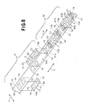
- Fig. 8 is a perspective-view schematically illustrating another embodiment of the process for attaching the indicator element
- Fig. 9 is a perspective view schematically illustrating the steps subsequent to the steps in the process illustrated in Fig. 8
- Fig. 10 is a perspective view schematically illustrating the steps subsequent to the steps in the process illustrated in Fig. 9 .
- a machine direction is indicated by an arrow X and a transverse (cross) direction is indicated by an arrow Y.
- the article 1B of Fig. 6 is manufactured and the indicator elements 13 are attached in the front and rear waist regions 4, 6 of the article 1B through successive steps as will be described.
- Step of feeding members S1 In the step of feeding members S1, a plurality of indication sheets 13 each extending in the machine direction are fed at regular intervals onto an outer surface of a continuous first outer layer web 30 while a plurality of the liquid-absorbent cores C each extending in the machine direction are fed at regular intervals onto an inner surface of the outer layer web 30.
- the outer layer web 30 is formed by the moisture-permeable but hydrophobic fibrous nonwoven fabric layer U2.
- the indication sheet 13 is formed by the moisture-permeable but liquid-impervious plastic film F1.
- Each of the indication sheets 13 has a front half 13a and a rear half 13b in which the indication sheet 13 is provided with a pair of the indicator elements 14.
- the indicator elements 14 comprise illustration of bear's faces printed on the outer surface of the indication sheet 13. These illustrations are in mirror image relationship with each other in the machine direction.
- the core C has, as viewed in the machine direction, a front end zone C1, a rear end zone C3 and an intermediate zone C2 extending between these end zones C1, C3.
- Step of placing members S2 In the step of placing members S2, the intermediate zone C2 of the core C is placed between each pair of the indication sheets 13 adjacent to each other in the machine direction; the rear half 13b of the indication sheet A13, that is, the front one of these adjacent indication sheets 13 as viewed in the machine direction, is placed upon the front end zone C1 of the core C; and the front half 13a of the indication sheet B13, that is, the rear one of these adjacent indication sheets 13 as viewed in the machine direction, is placed upon the rear end zone C3 of the core C.
- the indication sheets 13 are arranged at regular intervals in the machine direction in a transversely middle zone 30a on its outer surface.
- the cores C are arranged at regular intervals in the machine direction in the transversely middle zone 30a of the outer layer web 30 on its inner surface.
- the illustration 15 printed on the rear half 13b of the indication sheet 13 lies in the front end zone C1 of the core C and the illustration 15 printed on the front half 13a of the indication sheet 13 lies in the rear end zone C3 of the core C.
- Step of joining members S3 In the step of joining members S3, the indication sheet 13 is joined to the outer surface of the outer layer web 30 by means of a hot melt adhesive (not shown) and the lower surface of the core C is joined to the inner surface of the outer layer web 30 by means of a hot melt adhesive (not shown). After the members have been joined, the inner surface of the outer layer web 30 is placed upon an inner surface of the continuous inner layer web 31 and the inner surfaces of these webs 30, 31 are joined together by means of a hot melt adhesive (not shown). At the same time, the upper surface of the core C is attached to the inner surface of the inner layer web 31.
- a hot melt adhesive not shown
- the inner layer web 31 is formed by the moisture-permeable and hydrophilic fibrous nonwoven fabric layer U3.
- the adhesive is applied on the entire inner and outer surfaces of the outer layer web 30 and the entire inner surface of the inner layer web 31 in spiral-, zigzag-, dot- or stripe-pattern.
- Step of S4 In the step of forming panels S4, the outer layer web 30, the inner layer web 31 and the indication sheet 13 are cut along each first cutting line K1 to obtain a plurality of the inner panels 3 arranged in the machine direction.
- the first cutting line K1 extends in the transverse (cross) direction between each pair of the cores C adjacent to each other in the machine direction.
- the indication sheet 13 is divided into the front half 13a and the rear half 13b.
- the inner panel 3 has longitudinally opposite end zones 17 extending in the transverse (cross) direction and transversely opposite side edge zones 18 extending in the machine direction.
- Step of joining panels S5 In the step of joining panels S5, after the inner panels 3 arranged in the machine direction are successively turned round as indicated by an arrow Y2 approximately by 90°, and then, these inner panels 3 are placed at regular intervals on the inner surface of the continuous outer web 33. In the step of joining panels S5, the outer surface of the outer layer web 30 and the inner surface of the outer web 33 are joined together by means of a hot melt adhesive (not shown).
- the outer web 33 is formed by the moisture-permeable but hydrophobic fibrous nonwoven fabric layer U1 and the moisture-permeable but liquid-impervious plastic film F3 laminated on each other.
- the outer web 33 has a plurality of openings 34 arranged in the machine direction at regular intervals.
- the nonwoven fabric layer U1 and the film F3 opposed to each other are joined together by means of a hot melt adhesive (not shown).
- Each of these openings 34 has a spindle-shape which is relatively long in the transverse (cross) direction and the opening 34 is formed by cutting a corresponding portion away from the transversely middle zones 33a of the outer web 33.
- a plurality of stretchable elastic members 119 are attached in a stretched state to the periphery of the opening 34. These elastic members 119 are interposed-between the nonwoven fabric layer U1 and the film F3 and attached to the surfaces thereof opposed to each other.
- the inner panel 3 is located between each pair of the adjacent openings 34 of the outer web 33 so that the inner panels 3 are arranged on the inner surface of the outer web 33 at regular intervals in the machine direction.
- a plurality of second stretchable elastic members 16 are attached in a stretched state to the outer web 33 by means of a hot melt adhesive (not shown) (step of attaching waist elastic members 59).
- These elastic members 16 lie on both sides of the panel 3 and extend in the machine direction along transversely opposite side edges 33b of the outer web 33 so as to describe substantially straight lines.
- These elastic members 16 are interposed between the nonwoven fabric layer U1 and the film F3 and attached to the surfaces thereof opposed to each other.
- Step of forming articles S6 In the step of forming articles S6, the outer web 33 is cut along each second cutting line K2 to obtain a plurality of the articles 1B arranged in the machine direction.
- the second cutting line K2 extends in the transverse (cross) direction between each pair of the adjacent-inner panels 3.
- the article 1B has, in the transverse (cross) direction, a front waist region 4, a rear waist region 6 and a crotch region 5 extending between these two waist regions 4, 6.
- the article 1B may be folded along a fold guiding line D extending in the machine direction and bisecting a dimension of the outer web 33 as viewed in the transverse (cross) direction with the inner panel 3 inside and the waist's lateral zones 8 of the front and rear waist regions 4, 6 overlaid may be joined together by means of the heat-sealing lines 10 to form the article 1B in pants-type.
- first outer layer web 30 by a moisture-permeable but liquid-impervious plastic film. It is possible to form the second outer layer web 32 by a moisture-permeable but hydrophobic fibrous nonwoven fabric layer. It is also possible to form the outer web 33 by a composite nonwoven fabric layer comprising two layers of moisture-permeable but hydrophobic fibrous nonwoven fabric laminated with each other.
- a stock material for the fibrous nonwoven fabric layers U1, U2, U3 may be selected from the group consisting of those obtained by spun lace-, needle punch-, melt blown-, thermal bond-, spun bond-, chemical bond- and air through-processes.
- the component fibers of the nonwoven fabric layers U1, U2, U3 may be selected from the group consisting of polyolefin-, polyester- and polyamide-based fibers and core-and-sheath or side-by-side conjugated fibers of polyethylene/polypropylene or polyethylene/polyester.
- the plastic films F1, F2, F3 are preferably made of polyolefin-based thermoplastic synthetic resin.
- the present invention is applicable to, in addition to the pull-on disposable articles 1A, 1B having its front and rear waist regions 4, 6 previously connected with each other, also to an open-type disposable wearing article having its front and rear waist regions connected with each other immediately before put on the wearer's body.
- the step of forming articles includes no step of folding the article and, instead of this, a target tape strip may be attached to the outer surface of the outer web in the front waist region of the article and a pair of tape fasteners adapted to be anchored on the target tape strip may be attached to the waist's lateral zones in the rear waist region, respectively.
- the process according to this invention for attaching the indicator element is primarily characterized in that the indication sheet having a pair of indicator elements on the front and rear halves, respectively, is divided in two so that the indicator elements can be attached to each of the front and rear regions of the article all at once in the course of manufacturing a plurality of the articles arranged in the machine direction.
- This process makes it unnecessary to use means as well as steps for separately attaching the individual indicator elements to the front and rear waist regions. In this way, the indicator elements can be continuously attached to the front and rear regions of the articles at a high speed, on one hand, and the manufacturing cost can be reduced, on the other hand.
- the indication sheet having a pair of the illustrations printed on the indication sheet are in the mirror image relationship with each other in the machine direction and therefore there is no possibility that one of these illustrations respectively formed on the front and rear regions might be placed upside down with respect to the other illustration.
Landscapes
- Health & Medical Sciences (AREA)
- Engineering & Computer Science (AREA)
- Life Sciences & Earth Sciences (AREA)
- Animal Behavior & Ethology (AREA)
- Public Health (AREA)
- Heart & Thoracic Surgery (AREA)
- Vascular Medicine (AREA)
- Epidemiology (AREA)
- Veterinary Medicine (AREA)
- General Health & Medical Sciences (AREA)
- Biomedical Technology (AREA)
- Manufacturing & Machinery (AREA)
- Mechanical Engineering (AREA)
- Botany (AREA)
- Absorbent Articles And Supports Therefor (AREA)
- Orthopedics, Nursing, And Contraception (AREA)
- Professional, Industrial, Or Sporting Protective Garments (AREA)
Claims (11)
- Procédé pour fixer, dans les régions avant et arrière d'un vêtement jetable (1A) qui comprend une feuille externe (2) et un panneau interne (3) absorbant les liquides fixé à ladite feuille externe (2), des éléments indicateurs (14) qui sont visuellement reconnaissables de l'extérieur dudit vêtement, ledit procédé est caractérisé par les étapes suivantes :alimenter une pluralité de coeurs (C) absorbant les liquides ayant chacun des zones avant et arrière d'extrémité (C1, C3) et une zone intermédiaire (C2) et défilant dans une direction de machine (X) sur une surface interne d'une première bande continue de couche externe (30) et une bande continue interne (31) défilant dans la direction de machine (X), tout en alimentant une pluralité de feuilles d'indication (13) s'étendant chacune dans ladite direction de machine (X) et ayant lesdits éléments indicateurs (14) aux moitiés avant et arrière (13a, 13b) de ceux-ci, respectivement, à des intervalles réguliers dans ladite direction de machine (X) sur une surface externe de ladite première bande de couche externe (30) ;placer ladite zone intermédiaire (C2) dudit coeur (C) entre chaque paire de dites feuilles d'indication (13) adjacentes l'une à l'autre dans ladite direction de machine (X) de telle sorte qu'une moitié arrière (13b) de l'une des feuilles avant d'indication (13) adjacentes l'une à l'autre dans ladite direction de machine (X) est placée sur ladite zone d'extrémité avant (C1) dudit coeur (C), et ladite moitié avant d'une des feuilles d'indication (13) adjacentes les unes aux autres dans ladite direction de machine (X) est placée sur ladite zone d'extrémité arrière (C3) dudit coeur (C);relier ladite feuille d'indication (13) à ladite première bande de couche externe (30), reliant ledit coeur (C) à au moins une dite bande de couche interne (31) et une dite première bande de couche externe (30) et reliant des surfaces intérieures de ladite bande de couche interne (31) et ladite première bande de couche externe (30) par superposition ;former un panneau (3) en coupant lesdites feuilles d'indication (13) conjointement avec -lesdites premières bandes internes et externes de couche (31, 30) dans une direction transversale (Y) entre une paire desdits coeurs (C) adjacents les uns aux autres dans ladite direction de machine (X) de telle sorte que ladite feuille d'indication (13) est divisée en desdites moitiés avant et arrière (13a, 13b) pour obtenir une pluralité desdits panneaux internes (3) disposés dans ladite direction de machine (X) ; etplacer lesdits panneaux internes (3) situés à intervalles réguliers sur une surface intérieure d'une bande continue externe (33) défilant dans ladite direction de machine (X) après que lesdits panneaux intérieurs (3) soient retournés dans la direction transversale (Y) d'environ 90 ° et assemblage de ladite surface externe de ladite première bande de couche externe (30) à la surface de ladite bande externe (33).
- Procédé pour fixer des éléments indicateurs selon la revendication 1, comprenant en outre les étapes consistant à découper ladite bande externe (33) dans une zone médiane transversale (33a) pour former une pluralité d'ouvertures (34) disposées à intervalles réguliers dans ladite direction de machine (X), puis à placer lesdits panneaux Internes (3) entre chaque paire desdites ouvertures (34) adjacentes les unes aux autres, et à couper ladite bande externe (33) dans ladite direction transversale (Y) entre chaque paire desdits panneaux internes (3) adjacents les uns aux autres pour former une pluralité desdits vêtements (1A) disposés dans ladite direction de machine (X).
- Procédé pour fixer des éléments indicateurs selon la revendication 1, comprenant en outre les étapes consistant à couper une zone médiane transversale (33a) de ladite bande externe (33) s'étendant entre chaque paire desdits panneaux intérieurs (3) adjacents les uns aux autres pour former une pluralité d'ouvertures (34) disposées à intervalles réguliers dans ladite direction de machine (X) ; et à couper ladite bande externe (33) dans ladite direction transversale entre chaque paire desdits panneaux internes (3) adjacents les uns aux autres pour former une pluralité desdits vêtements (1A) disposés dans ladite direction de machine (X).
- Procédé pour fixer des éléments indicateurs selon l'une quelconque des revendications 1 à 3, comprenant en outre les étapes consistant à placer une surface intérieure d'une seconde bande continue externe de couche (32) défilant dans ladite direction de machine (X) sur ladite surface externe de ladite première bande externe de couche (30) et relier ladite première bande externe de couche (30) à ladite seconde bande externe de couche (32), couper les feuilles d'indication (13) en même temps que lesdites première et seconde bandes externes de couche (30, 32) et ladite bande interne de couche (31) dans ladite direction transversale entre chaque paire desdits coeurs (C) adjacents les uns aux autres dans ladite direction de machine (X), et relier une surface externe de ladite seconde bande externe de couche (32) à ladite surface interne de ladite bande externe (33).
- Procédé pour fixer des éléments indicateurs selon l'une quelconque des revendications 1 à 4, comprenant en outre l'étape de fixation de premiers éléments élastiques étirables (19) se trouvant des deux côtés desdits coeurs (C) et s'étendant dans ladite direction de machine (X) dans un état étiré à l'une des surfaces internes de ladite première bande externe de couche (30) et la surface interne de ladite bande interne de couche (31).
- Procédé pour fixer les éléments indicateurs selon l'une quelconque des revendications 1 à 4, qui comprend l'étape consistant à fixer lesdits première éléments élastiques extensibles (19) reposant sur les deux côtés desdits coeurs (C) et s'étendant dans ladite direction de machine (X) dans un état étiré en direction de l'une desdites premières surfaces internes de ladite première bande externe de couche (30) et ladite surface interne de ladite surface interne de ladite seconde bande externe de couche (32).
- Procédé pour fixer les éléments indicateurs selon l'une quelconque des revendications 1 à 6, comprenant en outre l'étape consistant à fixer des seconds éléments élastiques extensibles (16) placés des deux côtés de ladite bande externe (33) et s'étendant dans ladite direction de machine (X) dans un état étiré à ladite bande externe (33).
- Procédé pour fixer les éléments indicateurs selon l'une quelconque des revendications 2 à 7, dans lequel lesdites première et seconde bandes de couche externes (30, 32) sont formées par l'une des matières suivantes(i) un tissu non tissé fibreux hydrophobe et perméable à l'humidité(ii) un film plastique imperméable aux liquides et perméable à l'humidité, et ladite bande interne de couche (31) est formée par un tissu non tissé fibreux hydrophile.
- Procédé pour fixer les éléments indicateurs selon l'une quelconque des revendications 1 à 8, dans lequel ladite bande de couche externe (30) est formée par l'une des matières suivantes(i) un tissu non tissé fibreux hydrophobe et perméable à l'humidité,(ii) un tissu composite non tissé se composant de couches de tissu non tissé fibreux perméables à l'humidité mais hydrophobes, laminées les unes aux autres et(iii) une feuille composite composée d'un tissu non tissé fibreux hydrophobe perméable à l'humidité et d'un film plastique perméable à l'humidité mais imperméable aux liquides, laminés les uns aux autres.
- Procédé pour fixer les éléments indicateurs selon l'une quelconque des revendications 1 à 9, dans lequel ladite feuille d'indication (13) est formée par l'une des matières suivantes(i) un tissu non-tissé fibreux hydrophobe mais perméable à l'humidité, et(ii) un film plastique perméable à l'humidité mais imperméable aux liquides.
- Procédé pour fixer les éléments indicateurs selon l'une quelconque des revendications 1 à 10, dans lequel lesdits éléments indicateurs (14) comprennent une paire d'illustrations (15) imprimées sur lesdites moitiés avant et arrière (13a, 13b) de ladite feuille d'indication (13) et adjacente l'une de l'autre dans ladite direction de machine (X).
Applications Claiming Priority (3)
| Application Number | Priority Date | Filing Date | Title |
|---|---|---|---|
| JP2002236947A JP4116840B2 (ja) | 2002-08-15 | 2002-08-15 | 表示要素形成方法 |
| JP2002236947 | 2002-08-15 | ||
| PCT/JP2003/009261 WO2004016209A1 (fr) | 2002-08-15 | 2003-07-22 | Procede de realisation d'element de presentation |
Publications (3)
| Publication Number | Publication Date |
|---|---|
| EP1552802A1 EP1552802A1 (fr) | 2005-07-13 |
| EP1552802A4 EP1552802A4 (fr) | 2008-03-19 |
| EP1552802B1 true EP1552802B1 (fr) | 2012-09-05 |
Family
ID=31884426
Family Applications (1)
| Application Number | Title | Priority Date | Filing Date |
|---|---|---|---|
| EP03788011A Expired - Lifetime EP1552802B1 (fr) | 2002-08-15 | 2003-07-22 | Procede de realisation d'element de presentation |
Country Status (9)
| Country | Link |
|---|---|
| US (1) | US7189301B2 (fr) |
| EP (1) | EP1552802B1 (fr) |
| JP (1) | JP4116840B2 (fr) |
| KR (1) | KR100619556B1 (fr) |
| CN (1) | CN1303962C (fr) |
| AU (1) | AU2003248092B2 (fr) |
| BR (1) | BR0313573A (fr) |
| CA (1) | CA2494910C (fr) |
| WO (1) | WO2004016209A1 (fr) |
Families Citing this family (27)
| Publication number | Priority date | Publication date | Assignee | Title |
|---|---|---|---|---|
| JP4116839B2 (ja) * | 2002-08-15 | 2008-07-09 | ユニ・チャーム株式会社 | 表示要素形成方法 |
| JP4704826B2 (ja) | 2004-08-31 | 2011-06-22 | ユニ・チャーム株式会社 | 使い捨てパンツ型着用物品の製造方法 |
| JP4551193B2 (ja) | 2004-11-19 | 2010-09-22 | ユニ・チャーム株式会社 | 使い捨てパンツ型着用物品の製造方法 |
| US8007484B2 (en) | 2005-04-01 | 2011-08-30 | Curt G. Joa, Inc. | Pants type product and method of making the same |
| US20070142800A1 (en) * | 2005-12-20 | 2007-06-21 | The Procter & Gamble Company | Disposable absorbent articles having a partially visible graphic |
| JP4726673B2 (ja) * | 2006-03-28 | 2011-07-20 | 花王株式会社 | パンツ型吸収性物品及びその製造方法 |
| US7766887B2 (en) * | 2006-11-13 | 2010-08-03 | The Procter & Gamble Company | Method for making reusable disposable article |
| WO2009064224A1 (fr) * | 2007-11-14 | 2009-05-22 | Sca Hygiene Products Ab | Procédé de production d'un vêtement absorbant, et vêtement absorbant produit selon le procédé |
| RU2437641C1 (ru) * | 2007-11-14 | 2011-12-27 | Ска Хайджин Продактс Аб | Способ изготовления поглощающего предмета одежды и поглощающий предмет одежды, изготовленный в соответствии с данным способом |
| RU2441634C1 (ru) * | 2007-11-14 | 2012-02-10 | Ска Хайджин Продактс Аб | Способ изготовления поглощающего предмета одежды и поглощающий предмет одежды, изготовленный в соответствии с данным способом |
| WO2009064225A1 (fr) * | 2007-11-14 | 2009-05-22 | Sca Hygiene Products Ab | Procédé de production d'un vêtement absorbant, et vêtement absorbant produit selon le procédé |
| JP5513167B2 (ja) * | 2009-03-02 | 2014-06-04 | ユニ・チャーム株式会社 | コンベア装置及び吸収性物品の製造方法 |
| US8927801B2 (en) | 2009-04-13 | 2015-01-06 | The Procter & Gamble Company | Absorbent articles comprising wetness indicators |
| JP5237323B2 (ja) * | 2010-04-23 | 2013-07-17 | 株式会社瑞光 | パンツタイプ着用物品の製造方法 |
| USD676132S1 (en) | 2010-07-13 | 2013-02-12 | The Procter & Gamble Company | Absorbent article with a pattern |
| US8996410B2 (en) | 2010-07-13 | 2015-03-31 | The Procter & Gamble Company | Method of selling absorbent articles bearing similar and/or related graphics |
| US9398987B2 (en) | 2010-07-27 | 2016-07-26 | The Procter & Gamble Company | Method of printing graphics on absorbent-articles |
| IN2015DN00557A (fr) * | 2012-08-01 | 2015-06-26 | Procter & Gamble | |
| KR20160122742A (ko) * | 2014-02-18 | 2016-10-24 | 쥐디엠 에스.피.에이. | 흡수성 위생 용품을 성형하기 위한 기계 및 방법 |
| US20160038353A1 (en) * | 2014-08-07 | 2016-02-11 | The Procter & Gamble Company | Selection guide and array of absorbent articles |
| US10517773B2 (en) * | 2014-12-18 | 2019-12-31 | The Procter & Gamble Plaza | Apparatuses and methods for making absorbent articles |
| US20160175168A1 (en) * | 2014-12-18 | 2016-06-23 | The Procter & Gamble Company | Assembled Absorbent Article Components with Graphics Having Aligned Low Intensity Zones |
| JP6244495B1 (ja) * | 2016-08-31 | 2017-12-06 | ユニ・チャーム株式会社 | 吸収性物品に係るシート状部材の製造方法、及び製造装置 |
| JP6351686B2 (ja) | 2016-10-21 | 2018-07-04 | 大王製紙株式会社 | パンツタイプ使い捨ておむつ |
| JP6351685B2 (ja) | 2016-10-21 | 2018-07-04 | 大王製紙株式会社 | パンツタイプ使い捨ておむつ |
| JP6404297B2 (ja) | 2016-10-21 | 2018-10-10 | 大王製紙株式会社 | パンツタイプ使い捨ておむつ |
| JP6503428B2 (ja) | 2017-09-27 | 2019-04-17 | 大王製紙株式会社 | パンツタイプ使い捨ておむつ |
Family Cites Families (11)
| Publication number | Priority date | Publication date | Assignee | Title |
|---|---|---|---|---|
| JPH02234760A (ja) * | 1989-03-09 | 1990-09-17 | Uni Charm Corp | 使い捨て着用物品の製造方法 |
| JP3156251B2 (ja) * | 1990-10-26 | 2001-04-16 | 花王株式会社 | 使い捨て吸収性物品の製造方法 |
| JP3606297B2 (ja) * | 1996-10-21 | 2005-01-05 | 株式会社リブドゥコーポレーション | 使い捨ておむつの製造方法および該方法で得られた使い捨ておむつ |
| US6017406A (en) * | 1996-12-20 | 2000-01-25 | Kimberly-Clark Worldwide, Inc. | Methods for making absorbent articles with separate leg cuffs and waist pieces |
| US6652686B1 (en) * | 1999-02-08 | 2003-11-25 | Kimberly-Clark Worldwide, Inc. | Processes and apparatus for making disposable absorbent articles |
| JP3351763B2 (ja) * | 1999-07-19 | 2002-12-03 | 花王株式会社 | 吸収性物品の製造方法 |
| JP2001054536A (ja) * | 1999-08-20 | 2001-02-27 | Uni Charm Corp | 模様シートを有する使い捨ておむつおよびその製造方法 |
| US6558499B1 (en) * | 2000-01-21 | 2003-05-06 | Paragon Trade Brands, Inc. | Disposable absorbent article having graphics and process for making |
| US6788803B2 (en) * | 2001-12-14 | 2004-09-07 | Paragon Trade Brands, Inc. | Methods and systems for making disposable absorbent article having graphics |
| JP4116839B2 (ja) * | 2002-08-15 | 2008-07-09 | ユニ・チャーム株式会社 | 表示要素形成方法 |
| US7172667B2 (en) * | 2003-09-30 | 2007-02-06 | Tyco Healthcare Retail Services Ag | System and method for incorporating graphics into absorbent articles |
-
2002
- 2002-08-15 JP JP2002236947A patent/JP4116840B2/ja not_active Expired - Fee Related
-
2003
- 2003-07-22 KR KR1020057002482A patent/KR100619556B1/ko not_active Expired - Fee Related
- 2003-07-22 BR BR0313573-0A patent/BR0313573A/pt not_active IP Right Cessation
- 2003-07-22 EP EP03788011A patent/EP1552802B1/fr not_active Expired - Lifetime
- 2003-07-22 WO PCT/JP2003/009261 patent/WO2004016209A1/fr not_active Ceased
- 2003-07-22 CN CNB038190893A patent/CN1303962C/zh not_active Expired - Fee Related
- 2003-07-22 AU AU2003248092A patent/AU2003248092B2/en not_active Ceased
- 2003-07-22 CA CA002494910A patent/CA2494910C/fr not_active Expired - Fee Related
-
2004
- 2004-12-20 US US11/015,867 patent/US7189301B2/en not_active Expired - Lifetime
Also Published As
| Publication number | Publication date |
|---|---|
| CA2494910A1 (fr) | 2004-02-26 |
| KR100619556B1 (ko) | 2006-09-06 |
| EP1552802A4 (fr) | 2008-03-19 |
| CN1674847A (zh) | 2005-09-28 |
| AU2003248092A1 (en) | 2004-03-03 |
| WO2004016209A1 (fr) | 2004-02-26 |
| JP2004073428A (ja) | 2004-03-11 |
| CN1303962C (zh) | 2007-03-14 |
| JP4116840B2 (ja) | 2008-07-09 |
| US7189301B2 (en) | 2007-03-13 |
| US20050103436A1 (en) | 2005-05-19 |
| AU2003248092B2 (en) | 2007-10-18 |
| BR0313573A (pt) | 2005-07-12 |
| EP1552802A1 (fr) | 2005-07-13 |
| KR20060027788A (ko) | 2006-03-28 |
| CA2494910C (fr) | 2007-10-30 |
Similar Documents
| Publication | Publication Date | Title |
|---|---|---|
| EP1552802B1 (fr) | Procede de realisation d'element de presentation | |
| EP1366734B1 (fr) | Procédée pour le positionnement d'éléments indicateurs | |
| EP1366735B1 (fr) | Procédée pour le positionnement d'éléments indicateurs | |
| US7160408B2 (en) | Process for making a disposable diaper | |
| CA2187366C (fr) | Procede de fabrication de couche-culotte ou de culotte hygienique, et article produit | |
| USRE42478E1 (en) | Method of manufacturing a pants-type diaper of a sanitary panty, and one such absorbent article | |
| EP2688538B1 (fr) | Procédé de fabrication d'articles absorbants ayant une ceinture montée | |
| EP1205171A2 (fr) | Couche-culotte jetable | |
| EP1537842B1 (fr) | Article vestimentaire jetable | |
| EP2283797B1 (fr) | Article d'habillement en forme de culotte et son procédé de fabrication | |
| CA2360242C (fr) | Couche jetable a ceinture elastique avec dispositif de retenue des dechets | |
| EP1547560B1 (fr) | Procede de formation d'un element orne de motifs |
Legal Events
| Date | Code | Title | Description |
|---|---|---|---|
| PUAI | Public reference made under article 153(3) epc to a published international application that has entered the european phase |
Free format text: ORIGINAL CODE: 0009012 |
|
| 17P | Request for examination filed |
Effective date: 20050314 |
|
| AK | Designated contracting states |
Kind code of ref document: A1 Designated state(s): AT BE BG CH CY CZ DE DK EE ES FI FR GB GR HU IE IT LI LU MC NL PT RO SE SI SK TR |
|
| AX | Request for extension of the european patent |
Extension state: AL LT LV MK |
|
| DAX | Request for extension of the european patent (deleted) | ||
| A4 | Supplementary search report drawn up and despatched |
Effective date: 20080215 |
|
| 17Q | First examination report despatched |
Effective date: 20080603 |
|
| REG | Reference to a national code |
Ref country code: DE Ref legal event code: R079 Ref document number: 60342041 Country of ref document: DE Free format text: PREVIOUS MAIN CLASS: A61F0013514000 Ipc: A61F0013150000 |
|
| RIC1 | Information provided on ipc code assigned before grant |
Ipc: A61F 13/15 20060101AFI20111104BHEP Ipc: A61F 13/514 20060101ALI20111104BHEP Ipc: A61F 13/496 20060101ALI20111104BHEP |
|
| GRAP | Despatch of communication of intention to grant a patent |
Free format text: ORIGINAL CODE: EPIDOSNIGR1 |
|
| GRAS | Grant fee paid |
Free format text: ORIGINAL CODE: EPIDOSNIGR3 |
|
| GRAA | (expected) grant |
Free format text: ORIGINAL CODE: 0009210 |
|
| AK | Designated contracting states |
Kind code of ref document: B1 Designated state(s): AT BE BG CH CY CZ DE DK EE ES FI FR GB GR HU IE IT LI LU MC NL PT RO SE SI SK TR |
|
| REG | Reference to a national code |
Ref country code: GB Ref legal event code: FG4D |
|
| REG | Reference to a national code |
Ref country code: CH Ref legal event code: EP |
|
| REG | Reference to a national code |
Ref country code: AT Ref legal event code: REF Ref document number: 573746 Country of ref document: AT Kind code of ref document: T Effective date: 20120915 |
|
| REG | Reference to a national code |
Ref country code: IE Ref legal event code: FG4D |
|
| REG | Reference to a national code |
Ref country code: DE Ref legal event code: R096 Ref document number: 60342041 Country of ref document: DE Effective date: 20121031 |
|
| REG | Reference to a national code |
Ref country code: SE Ref legal event code: TRGR |
|
| REG | Reference to a national code |
Ref country code: AT Ref legal event code: MK05 Ref document number: 573746 Country of ref document: AT Kind code of ref document: T Effective date: 20120905 |
|
| REG | Reference to a national code |
Ref country code: NL Ref legal event code: VDEP Effective date: 20120905 |
|
| PG25 | Lapsed in a contracting state [announced via postgrant information from national office to epo] |
Ref country code: FI Free format text: LAPSE BECAUSE OF FAILURE TO SUBMIT A TRANSLATION OF THE DESCRIPTION OR TO PAY THE FEE WITHIN THE PRESCRIBED TIME-LIMIT Effective date: 20120905 Ref country code: CY Free format text: LAPSE BECAUSE OF FAILURE TO SUBMIT A TRANSLATION OF THE DESCRIPTION OR TO PAY THE FEE WITHIN THE PRESCRIBED TIME-LIMIT Effective date: 20120905 Ref country code: AT Free format text: LAPSE BECAUSE OF FAILURE TO SUBMIT A TRANSLATION OF THE DESCRIPTION OR TO PAY THE FEE WITHIN THE PRESCRIBED TIME-LIMIT Effective date: 20120905 |
|
| PG25 | Lapsed in a contracting state [announced via postgrant information from national office to epo] |
Ref country code: SI Free format text: LAPSE BECAUSE OF FAILURE TO SUBMIT A TRANSLATION OF THE DESCRIPTION OR TO PAY THE FEE WITHIN THE PRESCRIBED TIME-LIMIT Effective date: 20120905 Ref country code: GR Free format text: LAPSE BECAUSE OF FAILURE TO SUBMIT A TRANSLATION OF THE DESCRIPTION OR TO PAY THE FEE WITHIN THE PRESCRIBED TIME-LIMIT Effective date: 20121206 |
|
| PG25 | Lapsed in a contracting state [announced via postgrant information from national office to epo] |
Ref country code: NL Free format text: LAPSE BECAUSE OF FAILURE TO SUBMIT A TRANSLATION OF THE DESCRIPTION OR TO PAY THE FEE WITHIN THE PRESCRIBED TIME-LIMIT Effective date: 20120905 Ref country code: EE Free format text: LAPSE BECAUSE OF FAILURE TO SUBMIT A TRANSLATION OF THE DESCRIPTION OR TO PAY THE FEE WITHIN THE PRESCRIBED TIME-LIMIT Effective date: 20120905 Ref country code: ES Free format text: LAPSE BECAUSE OF FAILURE TO SUBMIT A TRANSLATION OF THE DESCRIPTION OR TO PAY THE FEE WITHIN THE PRESCRIBED TIME-LIMIT Effective date: 20121216 Ref country code: BE Free format text: LAPSE BECAUSE OF FAILURE TO SUBMIT A TRANSLATION OF THE DESCRIPTION OR TO PAY THE FEE WITHIN THE PRESCRIBED TIME-LIMIT Effective date: 20120905 Ref country code: CZ Free format text: LAPSE BECAUSE OF FAILURE TO SUBMIT A TRANSLATION OF THE DESCRIPTION OR TO PAY THE FEE WITHIN THE PRESCRIBED TIME-LIMIT Effective date: 20120905 Ref country code: RO Free format text: LAPSE BECAUSE OF FAILURE TO SUBMIT A TRANSLATION OF THE DESCRIPTION OR TO PAY THE FEE WITHIN THE PRESCRIBED TIME-LIMIT Effective date: 20120905 |
|
| PG25 | Lapsed in a contracting state [announced via postgrant information from national office to epo] |
Ref country code: PT Free format text: LAPSE BECAUSE OF FAILURE TO SUBMIT A TRANSLATION OF THE DESCRIPTION OR TO PAY THE FEE WITHIN THE PRESCRIBED TIME-LIMIT Effective date: 20130107 Ref country code: SK Free format text: LAPSE BECAUSE OF FAILURE TO SUBMIT A TRANSLATION OF THE DESCRIPTION OR TO PAY THE FEE WITHIN THE PRESCRIBED TIME-LIMIT Effective date: 20120905 |
|
| PLBE | No opposition filed within time limit |
Free format text: ORIGINAL CODE: 0009261 |
|
| STAA | Information on the status of an ep patent application or granted ep patent |
Free format text: STATUS: NO OPPOSITION FILED WITHIN TIME LIMIT |
|
| PG25 | Lapsed in a contracting state [announced via postgrant information from national office to epo] |
Ref country code: DK Free format text: LAPSE BECAUSE OF FAILURE TO SUBMIT A TRANSLATION OF THE DESCRIPTION OR TO PAY THE FEE WITHIN THE PRESCRIBED TIME-LIMIT Effective date: 20120905 Ref country code: BG Free format text: LAPSE BECAUSE OF FAILURE TO SUBMIT A TRANSLATION OF THE DESCRIPTION OR TO PAY THE FEE WITHIN THE PRESCRIBED TIME-LIMIT Effective date: 20121205 |
|
| 26N | No opposition filed |
Effective date: 20130606 |
|
| PG25 | Lapsed in a contracting state [announced via postgrant information from national office to epo] |
Ref country code: IT Free format text: LAPSE BECAUSE OF FAILURE TO SUBMIT A TRANSLATION OF THE DESCRIPTION OR TO PAY THE FEE WITHIN THE PRESCRIBED TIME-LIMIT Effective date: 20120905 |
|
| REG | Reference to a national code |
Ref country code: DE Ref legal event code: R097 Ref document number: 60342041 Country of ref document: DE Effective date: 20130606 |
|
| PG25 | Lapsed in a contracting state [announced via postgrant information from national office to epo] |
Ref country code: MC Free format text: LAPSE BECAUSE OF FAILURE TO SUBMIT A TRANSLATION OF THE DESCRIPTION OR TO PAY THE FEE WITHIN THE PRESCRIBED TIME-LIMIT Effective date: 20120905 |
|
| REG | Reference to a national code |
Ref country code: CH Ref legal event code: PL |
|
| REG | Reference to a national code |
Ref country code: IE Ref legal event code: MM4A |
|
| PG25 | Lapsed in a contracting state [announced via postgrant information from national office to epo] |
Ref country code: CH Free format text: LAPSE BECAUSE OF NON-PAYMENT OF DUE FEES Effective date: 20130731 Ref country code: LI Free format text: LAPSE BECAUSE OF NON-PAYMENT OF DUE FEES Effective date: 20130731 |
|
| PG25 | Lapsed in a contracting state [announced via postgrant information from national office to epo] |
Ref country code: IE Free format text: LAPSE BECAUSE OF NON-PAYMENT OF DUE FEES Effective date: 20130722 |
|
| PG25 | Lapsed in a contracting state [announced via postgrant information from national office to epo] |
Ref country code: TR Free format text: LAPSE BECAUSE OF FAILURE TO SUBMIT A TRANSLATION OF THE DESCRIPTION OR TO PAY THE FEE WITHIN THE PRESCRIBED TIME-LIMIT Effective date: 20120905 |
|
| PG25 | Lapsed in a contracting state [announced via postgrant information from national office to epo] |
Ref country code: HU Free format text: LAPSE BECAUSE OF FAILURE TO SUBMIT A TRANSLATION OF THE DESCRIPTION OR TO PAY THE FEE WITHIN THE PRESCRIBED TIME-LIMIT; INVALID AB INITIO Effective date: 20030722 Ref country code: LU Free format text: LAPSE BECAUSE OF NON-PAYMENT OF DUE FEES Effective date: 20130722 |
|
| REG | Reference to a national code |
Ref country code: FR Ref legal event code: PLFP Year of fee payment: 14 |
|
| REG | Reference to a national code |
Ref country code: FR Ref legal event code: PLFP Year of fee payment: 15 |
|
| REG | Reference to a national code |
Ref country code: FR Ref legal event code: PLFP Year of fee payment: 16 |
|
| PGFP | Annual fee paid to national office [announced via postgrant information from national office to epo] |
Ref country code: FR Payment date: 20180612 Year of fee payment: 16 |
|
| PGFP | Annual fee paid to national office [announced via postgrant information from national office to epo] |
Ref country code: DE Payment date: 20180710 Year of fee payment: 16 |
|
| PGFP | Annual fee paid to national office [announced via postgrant information from national office to epo] |
Ref country code: SE Payment date: 20180710 Year of fee payment: 16 Ref country code: GB Payment date: 20180718 Year of fee payment: 16 |
|
| REG | Reference to a national code |
Ref country code: DE Ref legal event code: R119 Ref document number: 60342041 Country of ref document: DE |
|
| REG | Reference to a national code |
Ref country code: SE Ref legal event code: EUG |
|
| GBPC | Gb: european patent ceased through non-payment of renewal fee |
Effective date: 20190722 |
|
| PG25 | Lapsed in a contracting state [announced via postgrant information from national office to epo] |
Ref country code: GB Free format text: LAPSE BECAUSE OF NON-PAYMENT OF DUE FEES Effective date: 20190722 Ref country code: DE Free format text: LAPSE BECAUSE OF NON-PAYMENT OF DUE FEES Effective date: 20200201 Ref country code: SE Free format text: LAPSE BECAUSE OF NON-PAYMENT OF DUE FEES Effective date: 20190723 |
|
| PG25 | Lapsed in a contracting state [announced via postgrant information from national office to epo] |
Ref country code: FR Free format text: LAPSE BECAUSE OF NON-PAYMENT OF DUE FEES Effective date: 20190731 |