EP1552174B1 - Verbindung für fadenschneider mit flexibler welle - Google Patents
Verbindung für fadenschneider mit flexibler welle Download PDFInfo
- Publication number
- EP1552174B1 EP1552174B1 EP03751908A EP03751908A EP1552174B1 EP 1552174 B1 EP1552174 B1 EP 1552174B1 EP 03751908 A EP03751908 A EP 03751908A EP 03751908 A EP03751908 A EP 03751908A EP 1552174 B1 EP1552174 B1 EP 1552174B1
- Authority
- EP
- European Patent Office
- Prior art keywords
- connector
- drive
- input area
- area
- angle
- Prior art date
- Legal status (The legal status is an assumption and is not a legal conclusion. Google has not performed a legal analysis and makes no representation as to the accuracy of the status listed.)
- Expired - Lifetime
Links
- 230000005540 biological transmission Effects 0.000 claims description 4
- HCHKCACWOHOZIP-UHFFFAOYSA-N Zinc Chemical compound [Zn] HCHKCACWOHOZIP-UHFFFAOYSA-N 0.000 claims description 3
- 239000011701 zinc Substances 0.000 claims description 3
- 229910052725 zinc Inorganic materials 0.000 claims description 3
- 238000012986 modification Methods 0.000 description 2
- 230000004048 modification Effects 0.000 description 2
- 230000004075 alteration Effects 0.000 description 1
- 230000008878 coupling Effects 0.000 description 1
- 238000010168 coupling process Methods 0.000 description 1
- 238000005859 coupling reaction Methods 0.000 description 1
- 238000003780 insertion Methods 0.000 description 1
- 230000037431 insertion Effects 0.000 description 1
- 230000007257 malfunction Effects 0.000 description 1
- 238000000034 method Methods 0.000 description 1
- 239000007787 solid Substances 0.000 description 1
- 238000012546 transfer Methods 0.000 description 1
Images


Classifications
-
- A—HUMAN NECESSITIES
- A01—AGRICULTURE; FORESTRY; ANIMAL HUSBANDRY; HUNTING; TRAPPING; FISHING
- A01D—HARVESTING; MOWING
- A01D34/00—Mowers; Mowing apparatus of harvesters
- A01D34/01—Mowers; Mowing apparatus of harvesters characterised by features relating to the type of cutting apparatus
- A01D34/412—Mowers; Mowing apparatus of harvesters characterised by features relating to the type of cutting apparatus having rotating cutters
- A01D34/416—Flexible line cutters
-
- F—MECHANICAL ENGINEERING; LIGHTING; HEATING; WEAPONS; BLASTING
- F16—ENGINEERING ELEMENTS AND UNITS; GENERAL MEASURES FOR PRODUCING AND MAINTAINING EFFECTIVE FUNCTIONING OF MACHINES OR INSTALLATIONS; THERMAL INSULATION IN GENERAL
- F16C—SHAFTS; FLEXIBLE SHAFTS; ELEMENTS OR CRANKSHAFT MECHANISMS; ROTARY BODIES OTHER THAN GEARING ELEMENTS; BEARINGS
- F16C1/00—Flexible shafts; Mechanical means for transmitting movement in a flexible sheathing
- F16C1/02—Flexible shafts; Mechanical means for transmitting movement in a flexible sheathing for conveying rotary movements
- F16C1/08—End connections
-
- F—MECHANICAL ENGINEERING; LIGHTING; HEATING; WEAPONS; BLASTING
- F16—ENGINEERING ELEMENTS AND UNITS; GENERAL MEASURES FOR PRODUCING AND MAINTAINING EFFECTIVE FUNCTIONING OF MACHINES OR INSTALLATIONS; THERMAL INSULATION IN GENERAL
- F16D—COUPLINGS FOR TRANSMITTING ROTATION; CLUTCHES; BRAKES
- F16D1/00—Couplings for rigidly connecting two coaxial shafts or other movable machine elements
- F16D1/10—Quick-acting couplings in which the parts are connected by simply bringing them together axially
- F16D1/101—Quick-acting couplings in which the parts are connected by simply bringing them together axially without axial retaining means rotating with the coupling
-
- F—MECHANICAL ENGINEERING; LIGHTING; HEATING; WEAPONS; BLASTING
- F16—ENGINEERING ELEMENTS AND UNITS; GENERAL MEASURES FOR PRODUCING AND MAINTAINING EFFECTIVE FUNCTIONING OF MACHINES OR INSTALLATIONS; THERMAL INSULATION IN GENERAL
- F16D—COUPLINGS FOR TRANSMITTING ROTATION; CLUTCHES; BRAKES
- F16D1/00—Couplings for rigidly connecting two coaxial shafts or other movable machine elements
- F16D1/10—Quick-acting couplings in which the parts are connected by simply bringing them together axially
- F16D2001/102—Quick-acting couplings in which the parts are connected by simply bringing them together axially the torque is transmitted via polygon shaped connections
-
- Y—GENERAL TAGGING OF NEW TECHNOLOGICAL DEVELOPMENTS; GENERAL TAGGING OF CROSS-SECTIONAL TECHNOLOGIES SPANNING OVER SEVERAL SECTIONS OF THE IPC; TECHNICAL SUBJECTS COVERED BY FORMER USPC CROSS-REFERENCE ART COLLECTIONS [XRACs] AND DIGESTS
- Y10—TECHNICAL SUBJECTS COVERED BY FORMER USPC
- Y10T—TECHNICAL SUBJECTS COVERED BY FORMER US CLASSIFICATION
- Y10T403/00—Joints and connections
- Y10T403/55—Member ends joined by inserted section
- Y10T403/551—Externally bridged
-
- Y—GENERAL TAGGING OF NEW TECHNOLOGICAL DEVELOPMENTS; GENERAL TAGGING OF CROSS-SECTIONAL TECHNOLOGIES SPANNING OVER SEVERAL SECTIONS OF THE IPC; TECHNICAL SUBJECTS COVERED BY FORMER USPC CROSS-REFERENCE ART COLLECTIONS [XRACs] AND DIGESTS
- Y10—TECHNICAL SUBJECTS COVERED BY FORMER USPC
- Y10T—TECHNICAL SUBJECTS COVERED BY FORMER US CLASSIFICATION
- Y10T403/00—Joints and connections
- Y10T403/70—Interfitted members
- Y10T403/7098—Non-circular rod section is joint component
Definitions
- This invention pertains to the art of apparatuses for flexible drive shafts for rotary power tools and more particularly to a flexible drive shaft with a connector that allows interchange of driven working ends.
- Flexible shafts comprise basic elements of power transmission and are designed to transmit power or control from a driving element to an element to be driven. Transmission may be over, under, or around obstacles or objects where transmission by solid shafts would be impractical or impossible.
- a wire mandrel In a typical rotatable flexible shaft, a wire mandrel has a plurality of layers of closely coiled wire wound thereover, each of the layers being successively wound over another in alternately opposing directions, i.e., right or left-hand lay.
- This shaft is usually covered by a flexible casing, metallic or covered, and a clearance between the shaft and casing is provided in order that the shaft may rotate freely within the casing.
- Rotatable flexible shafts are of two basic types--power driven and remotely controlled. Power driven flexible shafts are designed primarily for motor-driven or highspeed operation in one direction. Remote control flexible shafts, on the other hand, are designed primarily for hand-operated control in either direction.
- Power driven flexible shafts have two general classes of application--those in which there is relative movement between the driving and driven elements, and the curvature and twisting of the shaft is continually changing, as when, for example, a driven element such as a portable grinding tool is continuously moved about the workpiece by an operator and those in which the shaft operates in a given position and the curve, or curves, of the shaft remain substantially fixed, as in the coupling arrangement of the present invention wherein a shaft is used to transmit torque from a motor to a trimmer, for example.
- a fitting is permanently affixed to each end of the flexible shaft and the fitting suitably respectively connected to the output shaft of the motor and input shaft of the driven member.
- connection One problem with existing flexible drive shaft connections is the tendency for the connection to "strip" or break with use. Another problem with the existing connection designs is that it is difficult to effectively and completely insert the working member into the connection. This causes improper performance of the combination and can result in damage to the connection and/or drive shaft.
- the present invention provides for a flexible drive shaft with an improved connector connection for rotary power tools.
- the invention provides a drive shaft connector according to claim 1.
- the ratio of D 1 to D 2 is in the range from about 1:0.3125 to about 1:1.25, and the ratio of W 1 to W 2 is in the range from about 1:1.8 to about 1:3.2.
- the ratio of D 1 to D 2 is about 1:0.55 and the ratio of W 1 to W 2 is about 1:2.11.
- W 1 is about 5.21 mm (0.205 inches.)
- W 2 is about 10.97 mm (0.432 inches).
- D 1 is at least 10.16 mm (0.4 inches.)
- D 2 is at least 3.175 mm (0.125 inches), but not more than 12.7 mm (0.5 inches).
- the connector is made of zinc.
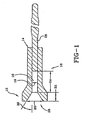
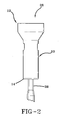
- FIGURES 1, 2, and 5 show a new and improved connector 10 for a flexible shaft (not shown), wherein the connector 10 has a drive area 16, an input area 26, a longitudinal axis 78, first end 12, and second end 14.
- the drive area 16 has a depth D 1 24.
- the input area 26 has a first end 52, a second end 54, a depth D 2 22, a width W 2 20, and a width W 1 18, with width W 2 20 being measured the first end 52, and the width W 1 18 being measured at the second end 54.
- the width W 2 20 is wider than the width W 1 18, and wider than the flexible shaft (not shown) for easier insertion of the flexible shaft.
- the connector 10 is connected to the drive shaft 28 at second end 14.
- the width W 1 18 is at least about 0.205 inches
- the width W 2 20 is between about 0.372 inches and about 0.654 inches.
- the depth D 1 24 is at least about 0.4 inches
- the depth D 2 22 is between about 0.125 inches and about 0.5 inches.
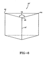
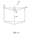
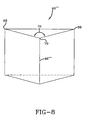
- the input area 26 has four sides 40, 40', 40", 40"', width W 2 20, drive opening 50, an angle ⁇ 1 30, and an angle ⁇ 2 38.
- Side 40 has an apex 46, a point a 32, point b 34, and point c 36.
- the angle ⁇ 2 38 created by points a, b, and c 32, 34, 36 is between 162° and 174°.
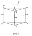
- FIGURE 4 shows side 40 of the input area 26.
- the side 40, at point b 34 is angled away from the center of the input area 26.
- the side 40, at point b 34 slopes downwardly from point b 34 to point e 58. This angle at points b, e 34, 58 is angle ⁇ 1 30.
- side 40' has point a 32, point g 62, point h 64, and angle ⁇ 3 72.
- Points a, g, and h 32, 62, 64 form angle ⁇ 3 72, which in this embodiment is between 162° and 174°.
- Side 40" has point h 64, point i 66, point j 68, and angle ⁇ 4 74.
- Points h, i, and j 64, 66, 68 form angle ⁇ 4 74, which in this embodiment is between 162° and 174°.
- Side 40''' has point j 68, point k 70, point c 36, and angle ⁇ 5 76.
- Points j, k, and c 68, 70, 36 form angle ⁇ 5 76, which in this embodiment is between 162° and 174°.
- Side 40' is connected to side 40 at point a 32 and to side 40" at point h 64, side 40" is connected to side 40''' at point j 68, and side 40''' is connected to side 40 at point c 36.
- Each side 40, 40', 40", 40''' has an angle ⁇ 1 30.
- This angle ⁇ 1 30 for each side 40, 40', 40", 40"' is between 21° and 34° in this embodiment.
- the angle ⁇ 1 30 is measured at points b, g, i, k 34, 62, 66, 70.
- the angle ⁇ 1 30 will increase as the sides 40, 40', 40", 40''' progress from points b, g, i, k 34, 62, 66, 70 to either points a, h, j, c 32, 64, 68, 36 or points c, a, h, j 36, 32, 64, 68, respectively.
- angles ⁇ 1 , ⁇ 2 , ⁇ 3 , ⁇ 4 , ⁇ 5 30, 38, 72, 74, 76 of the sides 40, 40', 40", 40''' allow the associated flexible shaft (not shown) to be easily and completely inserted into the drive area 16, which will prevent the stripping or breaking of the shaft caused by improper connection.
- the shaft When the shaft is inserted into the input area 26, the shaft may be slightly off-center with respect to the drive opening 50. In this case, the shaft would contact one of the sides 40, 40', 40'', 40''.
- the ⁇ 1 , ⁇ 2 , ⁇ 3 , ⁇ 4 , ⁇ 5 30, 38, 72, 74, 76 of the sides 40, 40', 40'', 40''' direct the shaft down into the drive opening 50, thereby ensuring a proper connection.
- the connector 10 is made of zinc, which will prevent breakage or accelerated wear of the connector 10. This also ensures that the torque created by the rotary power tool will be transferred efficiently from the drive shaft 28 to the driven working end (not shown).
- the connection of the connector 10 to the drive shaft 28, in one embodiment, can be a permanent connection. This ensures efficient transfer of the torque, as well as preventing malfunction of the flexible drive shaft/connector interconnection.
Landscapes
- Engineering & Computer Science (AREA)
- General Engineering & Computer Science (AREA)
- Mechanical Engineering (AREA)
- Health & Medical Sciences (AREA)
- Oral & Maxillofacial Surgery (AREA)
- Life Sciences & Earth Sciences (AREA)
- Environmental Sciences (AREA)
- Flexible Shafts (AREA)
- Knives (AREA)
- Shafts, Cranks, Connecting Bars, And Related Bearings (AREA)
Claims (9)
- Antriebswellenanschlußglied, das zur Aufnahme einer flexiblen Antriebswelle eines angetriebenen Elementes zur Kraftübertragung in einem Drehkraftwerkzeug ausgestaltet ist, wobei das Anschlußglied einen Anschlußgliedkörper mit einem ersten offenen Ende und einem mit einer Antriebswelle verbundenen, zweiten Ende aufweist, wobei eine Längsachse so definiert ist, daß sie zwischen dem ersten und dem zweiten Ende verläuft, wobei das Anschlußglied folgendes umfaßt:einen Antriebsbereich; undeinen Eingangsbereich am ersten Ende und benachbart zum Antriebsbereich, der zum Führen der flexiblen Welle des angetriebenen Elementes in den Antriebsbereich ausgestaltet ist, wobei der Eingangsbereich vier im wesentlichen ähnliche Seiten umfaßt, jede Seite einen ersten Punkt (32), einen zweiten Punkt (34), einen dritten Punkt (36) und einen vierten Punkt (58) aufweist, jede Seite eine erste ebene Fläche, die durch den ersten, den zweiten und den vierten Punkt (32, 34 und 58) definiert ist, und eine zweite ebene Fläche umfaßt, die durch den zweiten, dritten und vierten Punkt (34, 36 und 58) definiert ist, dadurch gekennzeichnet, daß die erste und die zweite Fläche an einem Scheitel konvergieren, der jede Seite derart halbiert, daß die erste und die zweite ebene Fläche Spiegelbilder voneinander sind, und der zweite und der vierte Punkt (34 und 58) auf dem Scheitel angeordnet sind, wobei der Scheitel sich nach innen in Richtung des Antriebsbereiches unter einem ersten Winkel bezüglich der Längsachse neigt, und der erste Winkel in einem Bereich zwischen etwa 21° bis etwa 34° liegt, und der erste, der zweite und der dritte Punkt (32, 34 und 36) eine Außenkante des offenen Eingangsbereiches definieren und einen stumpfen, zweiten Winkel bilden, wobei der zweite Winkel im Bereich von etwa 162° bis etwa 174° liegt.
- Anschlußglied nach Anspruch 1, bei dem der erste Winkel etwa 24° ist und der zweite Winkel etwa 168° ist.
- Anschlußglied nach Anspruch 1, bei dem der Antriebsbereich eine Breite (W1) und eine Tiefe (D1) hat und der Eingangsbereich eine Breite (W2) und eine Tiefe (D2) hat, wobei das Verhältnis der Antriebsbereichstiefe (D1) zur Eingangsbereichstiefe (D2) im Bereich von etwa 1:0.3125 bis etwa 1:1.25 liegt und das Verhältnis der Antriebsbereichsbreite (W1) zur Eingangsbereichsbreite (W2) im Bereich von etwa 1:1.8 bis etwa 1:3.2 liegt.
- Anschlußglied nach Anspruch 3, bei dem das Verhältnis der Antriebsbereichstiefe (D1) zur Eingangsbereichstiefe (D2) etwa 1:0.55 ist und das Verhältnis der Antriebsbereichsbreite (W1) zur Eingangsbereichsbreite (W2) etwa 1:2.11 ist.
- Anschlußglied nach Anspruch 4, bei dem die Antriebsbereichsbreite (W1) etwa 5.21 mm (0.205 inches) ist.
- Anschlußglied nach Anspruch 3, bei dem die Eingangsbereichsbreite (W2) etwa 10.97 mm (0.432 inches) ist.
- Anschlußglied nach Anspruch 3, bei dem die Antriebsbereichstiefe (D1) wenigstens 10.16 mm (0.4 inches) ist.
- Anschlußglied nach Anspruch 3, bei dem die Eingangsbereichstiefe (D2) wenigstens 3.175 mm (0.125 inches) ist, jedoch nicht mehr als 12.7 mm (0.5 inches).
- Anschlußglied nach Anspruch 1, bei dem das Anschlußglied aus Zink hergestellt ist.
Applications Claiming Priority (3)
| Application Number | Priority Date | Filing Date | Title |
|---|---|---|---|
| US10/272,383 US7004668B2 (en) | 2002-10-16 | 2002-10-16 | Connector for flex shaft for string trimmer |
| US272383 | 2002-10-16 | ||
| PCT/US2003/026820 WO2004036075A1 (en) | 2002-10-16 | 2003-08-26 | Connector for flex shaft for string trimmer |
Publications (2)
| Publication Number | Publication Date |
|---|---|
| EP1552174A1 EP1552174A1 (de) | 2005-07-13 |
| EP1552174B1 true EP1552174B1 (de) | 2007-01-03 |
Family
ID=32092599
Family Applications (1)
| Application Number | Title | Priority Date | Filing Date |
|---|---|---|---|
| EP03751908A Expired - Lifetime EP1552174B1 (de) | 2002-10-16 | 2003-08-26 | Verbindung für fadenschneider mit flexibler welle |
Country Status (6)
| Country | Link |
|---|---|
| US (1) | US7004668B2 (de) |
| EP (1) | EP1552174B1 (de) |
| AU (1) | AU2003270013A1 (de) |
| BR (1) | BR0315377A (de) |
| DE (1) | DE60310972T2 (de) |
| WO (1) | WO2004036075A1 (de) |
Families Citing this family (13)
| Publication number | Priority date | Publication date | Assignee | Title |
|---|---|---|---|---|
| US20080173000A1 (en) * | 2007-01-23 | 2008-07-24 | Moe Industries | Pto driven implement and interchange system |
| JP4651056B2 (ja) * | 2008-10-28 | 2011-03-16 | 日本航空電子工業株式会社 | アダプタ装置 |
| US8641314B2 (en) * | 2010-02-01 | 2014-02-04 | Hyclone Laboratories, Inc. | Quick coupling for drive shaft |
| US8506198B2 (en) * | 2010-02-01 | 2013-08-13 | Hyclone Laboratories, Inc. | Self aligning coupling for mixing system |
| US8381834B2 (en) * | 2010-02-04 | 2013-02-26 | Robert Bosch Gmbh | Drive system for interconnecting attachment devices and handheld rotary power tools |
| JP2013208678A (ja) * | 2012-03-30 | 2013-10-10 | Hitachi Koki Co Ltd | インパクト工具 |
| USD687270S1 (en) * | 2012-03-30 | 2013-08-06 | Techtronic Outdoor Products Technology Limited | Interface for a connector for a lawn tool |
| USD687684S1 (en) * | 2012-03-30 | 2013-08-13 | Techtronic Outdoor Products Technology Limited | Interface for a connector for a lawn tool |
| BR112017021091A2 (pt) * | 2015-04-02 | 2018-07-03 | Sandvik Intellectual Property Ab | conector multi funcional, cabeça de perfuração e método para perfuração |
| US10660269B2 (en) * | 2018-01-22 | 2020-05-26 | William G. Pendleton | Device for extracting and using auxiliary power |
| CN116352659A (zh) * | 2021-12-28 | 2023-06-30 | 创科无线普通合伙 | 作业工具及其传动系统 |
| US20230234202A1 (en) * | 2022-01-27 | 2023-07-27 | Shukla Medical | Power adapter for a powered tool |
| US20230302620A1 (en) * | 2022-03-28 | 2023-09-28 | Milwaukee Electric Tool Corporation | Rotary power tool |
Family Cites Families (38)
| Publication number | Priority date | Publication date | Assignee | Title |
|---|---|---|---|---|
| US1601099A (en) | 1923-01-24 | 1926-09-28 | Arens Charles | Power-transmitting device |
| US1775402A (en) | 1925-01-26 | 1930-09-09 | Husky Corp | Wrench outfit |
| US1678335A (en) | 1927-02-28 | 1928-07-24 | Mall Tool Company | Flexible shaft |
| US1871528A (en) | 1930-01-17 | 1932-08-16 | White S Dental Mfg Co | Flexible shaft and casing assembly |
| US2319409A (en) | 1940-08-03 | 1943-05-18 | White S Dental Mfg Co | Flexible shaft |
| US2370884A (en) | 1943-08-05 | 1945-03-06 | Smith Joseph Leigh | Flexible shaft |
| US2704005A (en) | 1953-08-07 | 1955-03-15 | Kenneth D Clayson | Torque-transmitting tool having rotat-able housing and bendable but stationary core |
| US2869907A (en) | 1956-07-20 | 1959-01-20 | Deliso John | Socket and rod coupling |
| US2917909A (en) | 1956-09-28 | 1959-12-22 | Josutis Willi | Flexible joints |
| US3440836A (en) | 1967-11-01 | 1969-04-29 | Gen Motors Corp | Flexible cable and casing adaptor tip assembly |
| US3540123A (en) | 1967-12-05 | 1970-11-17 | Kunimi Yamada | Mowing machine |
| US3481156A (en) | 1968-03-29 | 1969-12-02 | Pennsalt Chemicals Corp | Power transmission assembly |
| US3505831A (en) | 1968-07-05 | 1970-04-14 | Skil Corp | Flexible shaft coupler |
| US3855817A (en) | 1972-04-19 | 1974-12-24 | Gates Rubber Co | Flexible shaft |
| US3977078A (en) | 1975-06-17 | 1976-08-31 | Pittinger Jr Charles B | Grass cutting chain saw drive system |
| US4126063A (en) * | 1975-11-14 | 1978-11-21 | Palmer Richard R | Wrench sockets |
| US4057114A (en) | 1976-01-07 | 1977-11-08 | Anderson Paul J | Hand-held ice auger |
| FR2376328A1 (fr) | 1976-12-29 | 1978-07-28 | Jaeger | Dispositif de centrage du carre terminal d'un arbre flexible, dans son embout de raccordement |
| US4126928A (en) | 1977-04-18 | 1978-11-28 | Hoffco, Inc. | Method of making a shaft assembly |
| US4226021A (en) | 1978-10-19 | 1980-10-07 | Hoffco, Inc. | Shaft assembly for lawn trimmer |
| US4242855A (en) | 1979-02-22 | 1981-01-06 | Beaver Jr B Max | Lawn mower auxiliary unit with flexible drive shaft |
| US4286675A (en) | 1979-06-25 | 1981-09-01 | Beaird-Poulan Division Of Emerson Electric Co. | Narrow profile power handle for line trimmer and the like |
| US4451983A (en) | 1979-11-19 | 1984-06-05 | Emerson Electric Co. | Plastic flexible shaft support |
| US4541160A (en) | 1981-02-23 | 1985-09-17 | Roberts Thomas C | Process of using a flexible shaft motor coupling having interchangeable adaptors |
| JPS57186612A (en) * | 1981-05-13 | 1982-11-17 | Yazaki Corp | Coupling device of flexible cable to meter |
| US4416644A (en) * | 1982-02-01 | 1983-11-22 | Pennwalt Corporation | Flexible shaft assembly with universal adapter |
| US4483070A (en) | 1982-09-21 | 1984-11-20 | Joane G. Tannehill | Portable backpacked cutter |
| JPS60190220U (ja) | 1984-05-25 | 1985-12-17 | 株式会社共立 | 直杆形刈払機 |
| US4653254A (en) | 1985-08-27 | 1987-03-31 | Qualls Charles W | Auxiliary power apparatus |
| US5035055A (en) | 1987-05-08 | 1991-07-30 | Mccullough Timothy J | Flexible drive shaft casing |
| US4989323A (en) | 1989-06-05 | 1991-02-05 | Caspro Mechanical Technologies, Inc. | Portable power unit for various power tolls |
| DE8909363U1 (de) | 1989-08-03 | 1989-10-05 | Süddeutsche Kühlerfabrik Julius Fr. Behr GmbH & Co KG, 7000 Stuttgart | Verbindungseinrichtung für Klappen, insbesondere für Klappen einer Belüftungs- oder Klimaanlage für Kraftfahrzeuge |
| US5062734A (en) | 1990-11-08 | 1991-11-05 | Vanzee David G | Shaft coupling device |
| US5215413A (en) * | 1991-07-26 | 1993-06-01 | Westinghouse Electric Corp. | Composite-to-metal shaft joint |
| CA2059839C (en) | 1992-01-22 | 1998-09-29 | Fred Blumentrath | Shaft coupler |
| US6003411A (en) * | 1998-02-02 | 1999-12-21 | Snap-On Tools Company | Cam-lobed salvage tool |
| US6122830A (en) * | 1999-02-08 | 2000-09-26 | Jarzombek; Richard J. | Self-powered device for wearing on the back and for cutting foliage |
| US6626067B1 (en) * | 2000-09-27 | 2003-09-30 | Snap-On Technologies, Inc. | Retention socket geometry variations |
-
2002
- 2002-10-16 US US10/272,383 patent/US7004668B2/en not_active Expired - Fee Related
-
2003
- 2003-08-26 EP EP03751908A patent/EP1552174B1/de not_active Expired - Lifetime
- 2003-08-26 WO PCT/US2003/026820 patent/WO2004036075A1/en not_active Ceased
- 2003-08-26 AU AU2003270013A patent/AU2003270013A1/en not_active Abandoned
- 2003-08-26 DE DE60310972T patent/DE60310972T2/de not_active Expired - Fee Related
- 2003-08-26 BR BR0315377-0A patent/BR0315377A/pt not_active Application Discontinuation
Also Published As
| Publication number | Publication date |
|---|---|
| US20040076467A1 (en) | 2004-04-22 |
| EP1552174A1 (de) | 2005-07-13 |
| AU2003270013A2 (en) | 2004-05-04 |
| AU2003270013A1 (en) | 2004-05-04 |
| DE60310972T2 (de) | 2007-04-19 |
| WO2004036075A1 (en) | 2004-04-29 |
| US7004668B2 (en) | 2006-02-28 |
| BR0315377A (pt) | 2005-08-23 |
| DE60310972D1 (de) | 2007-02-15 |
Similar Documents
| Publication | Publication Date | Title |
|---|---|---|
| EP1552174B1 (de) | Verbindung für fadenschneider mit flexibler welle | |
| EP0365703B1 (de) | Handgeführte Maschine | |
| US4706659A (en) | Flexible connecting shaft for intramedullary reamer | |
| US5911283A (en) | Sectional drive system | |
| US5732432A (en) | Electric toothbrushes | |
| US6401837B1 (en) | Charging type multipurpose combination tool | |
| JP4482303B2 (ja) | 先細チゼル | |
| US5396945A (en) | Drive mechanism for slatted blinds | |
| EP3257643B1 (de) | Staubabsaugbohrer, system und staubsaugeinheit | |
| CA2095399A1 (en) | Apparatus for removing snow and ice | |
| ITPN960001U1 (it) | Dispositivo di bloccaggio per albero di comando | |
| JP2006034813A (ja) | 自走式掃除機 | |
| CN104622534A (zh) | 外科机头 | |
| JPH11285911A (ja) | ドリル工具及び/又はたがね工具 | |
| WO2006001622A1 (en) | Flexible transmission shaft | |
| EP1102913B1 (de) | Drehbares zugspannungselement im bohrloch | |
| US7329189B2 (en) | Flex drive connector | |
| CA2359150A1 (en) | Torque-transmitting arrangement | |
| US11185963B2 (en) | Hand-held power tool and mechanical striking mechanism | |
| JP4090484B2 (ja) | 曲折用アタッチメントおよびこれを装着してなる携帯型刈払機 | |
| EP3909526A2 (de) | Werkzeugantriebsanordnung | |
| US7156628B2 (en) | Wobblestick with helix | |
| US2446964A (en) | Sewer mole | |
| CN215534193U (zh) | 一种蛇骨组和蛇骨管 | |
| US1977224A (en) | Handle and cable housing for electric devices |
Legal Events
| Date | Code | Title | Description |
|---|---|---|---|
| PUAI | Public reference made under article 153(3) epc to a published international application that has entered the european phase |
Free format text: ORIGINAL CODE: 0009012 |
|
| 17P | Request for examination filed |
Effective date: 20050428 |
|
| AK | Designated contracting states |
Kind code of ref document: A1 Designated state(s): AT BE BG CH CY CZ DE DK EE ES FI FR GB GR HU IE IT LI LU MC NL PT RO SE SI SK TR |
|
| AX | Request for extension of the european patent |
Extension state: AL LT LV MK |
|
| DAX | Request for extension of the european patent (deleted) | ||
| RBV | Designated contracting states (corrected) |
Designated state(s): DE FR GB |
|
| GRAP | Despatch of communication of intention to grant a patent |
Free format text: ORIGINAL CODE: EPIDOSNIGR1 |
|
| GRAS | Grant fee paid |
Free format text: ORIGINAL CODE: EPIDOSNIGR3 |
|
| GRAA | (expected) grant |
Free format text: ORIGINAL CODE: 0009210 |
|
| AK | Designated contracting states |
Kind code of ref document: B1 Designated state(s): DE FR GB |
|
| REG | Reference to a national code |
Ref country code: GB Ref legal event code: FG4D |
|
| REF | Corresponds to: |
Ref document number: 60310972 Country of ref document: DE Date of ref document: 20070215 Kind code of ref document: P |
|
| ET | Fr: translation filed | ||
| PLBE | No opposition filed within time limit |
Free format text: ORIGINAL CODE: 0009261 |
|
| STAA | Information on the status of an ep patent application or granted ep patent |
Free format text: STATUS: NO OPPOSITION FILED WITHIN TIME LIMIT |
|
| 26N | No opposition filed |
Effective date: 20071005 |
|
| PGFP | Annual fee paid to national office [announced via postgrant information from national office to epo] |
Ref country code: FR Payment date: 20080710 Year of fee payment: 6 |
|
| PGFP | Annual fee paid to national office [announced via postgrant information from national office to epo] |
Ref country code: GB Payment date: 20080814 Year of fee payment: 6 |
|
| PGFP | Annual fee paid to national office [announced via postgrant information from national office to epo] |
Ref country code: DE Payment date: 20080930 Year of fee payment: 6 |
|
| GBPC | Gb: european patent ceased through non-payment of renewal fee |
Effective date: 20090826 |
|
| REG | Reference to a national code |
Ref country code: FR Ref legal event code: ST Effective date: 20100430 |
|
| PG25 | Lapsed in a contracting state [announced via postgrant information from national office to epo] |
Ref country code: DE Free format text: LAPSE BECAUSE OF NON-PAYMENT OF DUE FEES Effective date: 20100302 Ref country code: FR Free format text: LAPSE BECAUSE OF NON-PAYMENT OF DUE FEES Effective date: 20090831 |
|
| PG25 | Lapsed in a contracting state [announced via postgrant information from national office to epo] |
Ref country code: GB Free format text: LAPSE BECAUSE OF NON-PAYMENT OF DUE FEES Effective date: 20090826 |