EP1552048B1 - Method for holding a weft yarn, jet weaving machine comprising a clamping device for the weft yarn, particularly serving to carry out this method, and cartridge provided in the form of an exchangeable modular unit for placing inside the mixing tube of a jet weaving machine - Google Patents
Method for holding a weft yarn, jet weaving machine comprising a clamping device for the weft yarn, particularly serving to carry out this method, and cartridge provided in the form of an exchangeable modular unit for placing inside the mixing tube of a jet weaving machine Download PDFInfo
- Publication number
- EP1552048B1 EP1552048B1 EP03750289A EP03750289A EP1552048B1 EP 1552048 B1 EP1552048 B1 EP 1552048B1 EP 03750289 A EP03750289 A EP 03750289A EP 03750289 A EP03750289 A EP 03750289A EP 1552048 B1 EP1552048 B1 EP 1552048B1
- Authority
- EP
- European Patent Office
- Prior art keywords
- lamellar
- mixing tube
- jet loom
- clamping
- clamping parts
- Prior art date
- Legal status (The legal status is an assumption and is not a legal conclusion. Google has not performed a legal analysis and makes no representation as to the accuracy of the status listed.)
- Expired - Lifetime
Links
- 238000000034 method Methods 0.000 title claims description 28
- 238000009941 weaving Methods 0.000 title abstract description 9
- 210000003205 muscle Anatomy 0.000 claims abstract description 56
- 238000003780 insertion Methods 0.000 claims abstract description 29
- 230000037431 insertion Effects 0.000 claims abstract description 29
- 230000009471 action Effects 0.000 claims description 17
- 230000008878 coupling Effects 0.000 claims description 17
- 238000010168 coupling process Methods 0.000 claims description 17
- 238000005859 coupling reaction Methods 0.000 claims description 17
- 238000010276 construction Methods 0.000 claims description 6
- 230000000694 effects Effects 0.000 claims description 5
- 238000003825 pressing Methods 0.000 claims description 3
- 239000012858 resilient material Substances 0.000 claims description 3
- 239000007769 metal material Substances 0.000 claims description 2
- 230000000295 complement effect Effects 0.000 claims 1
- 239000000463 material Substances 0.000 claims 1
- 230000013011 mating Effects 0.000 claims 1
- 238000007664 blowing Methods 0.000 description 7
- 230000008901 benefit Effects 0.000 description 5
- 238000007789 sealing Methods 0.000 description 4
- 239000007787 solid Substances 0.000 description 4
- 239000013013 elastic material Substances 0.000 description 3
- 238000009434 installation Methods 0.000 description 3
- 230000006835 compression Effects 0.000 description 2
- 238000007906 compression Methods 0.000 description 2
- 238000005299 abrasion Methods 0.000 description 1
- 238000004026 adhesive bonding Methods 0.000 description 1
- 230000002411 adverse Effects 0.000 description 1
- 238000005219 brazing Methods 0.000 description 1
- 238000005520 cutting process Methods 0.000 description 1
- 238000006073 displacement reaction Methods 0.000 description 1
- 239000000428 dust Substances 0.000 description 1
- 230000002349 favourable effect Effects 0.000 description 1
- 230000010354 integration Effects 0.000 description 1
- 230000003993 interaction Effects 0.000 description 1
- 239000002184 metal Substances 0.000 description 1
- 239000000203 mixture Substances 0.000 description 1
- 229920001296 polysiloxane Polymers 0.000 description 1
- 230000008569 process Effects 0.000 description 1
- 230000002250 progressing effect Effects 0.000 description 1
- 230000000717 retained effect Effects 0.000 description 1
- 238000000926 separation method Methods 0.000 description 1
- 230000035939 shock Effects 0.000 description 1
- 210000002105 tongue Anatomy 0.000 description 1
- 238000003466 welding Methods 0.000 description 1
Images


Classifications
-
- D—TEXTILES; PAPER
- D03—WEAVING
- D03D—WOVEN FABRICS; METHODS OF WEAVING; LOOMS
- D03D47/00—Looms in which bulk supply of weft does not pass through shed, e.g. shuttleless looms, gripper shuttle looms, dummy shuttle looms
- D03D47/28—Looms in which bulk supply of weft does not pass through shed, e.g. shuttleless looms, gripper shuttle looms, dummy shuttle looms wherein the weft itself is projected into the shed
- D03D47/30—Looms in which bulk supply of weft does not pass through shed, e.g. shuttleless looms, gripper shuttle looms, dummy shuttle looms wherein the weft itself is projected into the shed by gas jet
- D03D47/3026—Air supply systems
- D03D47/3053—Arrangements or lay out of air supply systems
-
- B—PERFORMING OPERATIONS; TRANSPORTING
- B65—CONVEYING; PACKING; STORING; HANDLING THIN OR FILAMENTARY MATERIAL
- B65H—HANDLING THIN OR FILAMENTARY MATERIAL, e.g. SHEETS, WEBS, CABLES
- B65H63/00—Warning or safety devices, e.g. automatic fault detectors, stop-motions ; Quality control of the package
- B65H63/08—Warning or safety devices, e.g. automatic fault detectors, stop-motions ; Quality control of the package responsive to delivery of a measured length of material, completion of winding of a package, or filling of a receptacle
- B65H63/088—Clamping device
-
- D—TEXTILES; PAPER
- D03—WEAVING
- D03D—WOVEN FABRICS; METHODS OF WEAVING; LOOMS
- D03D47/00—Looms in which bulk supply of weft does not pass through shed, e.g. shuttleless looms, gripper shuttle looms, dummy shuttle looms
- D03D47/28—Looms in which bulk supply of weft does not pass through shed, e.g. shuttleless looms, gripper shuttle looms, dummy shuttle looms wherein the weft itself is projected into the shed
- D03D47/30—Looms in which bulk supply of weft does not pass through shed, e.g. shuttleless looms, gripper shuttle looms, dummy shuttle looms wherein the weft itself is projected into the shed by gas jet
- D03D47/3006—Construction of the nozzles
- D03D47/3013—Main nozzles
-
- D—TEXTILES; PAPER
- D03—WEAVING
- D03D—WOVEN FABRICS; METHODS OF WEAVING; LOOMS
- D03D47/00—Looms in which bulk supply of weft does not pass through shed, e.g. shuttleless looms, gripper shuttle looms, dummy shuttle looms
- D03D47/34—Handling the weft between bulk storage and weft-inserting means
-
- B—PERFORMING OPERATIONS; TRANSPORTING
- B65—CONVEYING; PACKING; STORING; HANDLING THIN OR FILAMENTARY MATERIAL
- B65H—HANDLING THIN OR FILAMENTARY MATERIAL, e.g. SHEETS, WEBS, CABLES
- B65H2555/00—Actuating means
- B65H2555/10—Actuating means linear
- B65H2555/11—Actuating means linear pneumatic, e.g. inflatable elements
-
- B—PERFORMING OPERATIONS; TRANSPORTING
- B65—CONVEYING; PACKING; STORING; HANDLING THIN OR FILAMENTARY MATERIAL
- B65H—HANDLING THIN OR FILAMENTARY MATERIAL, e.g. SHEETS, WEBS, CABLES
- B65H2701/00—Handled material; Storage means
- B65H2701/30—Handled filamentary material
- B65H2701/31—Textiles threads or artificial strands of filaments
Definitions
- the invention relates to a method for holding and releasing a weft thread in the region of the main blowing nozzle of a jet loom, in particular air jet loom, wherein the weft is clamped before its entry in a shed formed by warp sheds in the direction of entry to an injector of the Hauptblasdüse and released shortly before its entry.
- the invention also relates to a jet loom, in particular air jet loom with multicolor weft insertion for carrying out the method, with at least one Hauptblasdüse comprising an injector with subsequent mixing tube, and with a clamping device for clamping a weft thread in the mixing tube or directly at the outlet opening of the mixing tube.
- DE 32 00 638 A1 discloses a method and a jet loom of this type as known.
- the clamping device is arranged in the region of the outlet end of the mixing tube, in which the weft thread passes into the shed.
- the clamping device may consist of a slide which is displaceable transversely to the longitudinal direction of the mixing tube as a lifting member and clamps the weft thread located in the mixing tube between the passage opening of the slide and the inner wall of the mixing tube.
- Another embodiment provides a transversely displaceable punch which presses the weft thread against the inner wall of the mixing tube.
- a further embodiment of the known clamping device is provided, according to which a portion of the mixing tube is formed as an elastic intermediate piece.
- the intermediate piece is to be compressed by two diametrically opposed lifting members, when they are moved against each other.
- the weft thread is clamped by the compressed elastic intermediate piece.
- the weft thread is displaced laterally during clamping, that is no longer in the central longitudinal axis of the mixing tube. Also in the third embodiment, this phenomenon is to be feared because only two lifting members are provided for compressing the elastic intermediate piece, the compression is therefore not strict can be centrally symmetric. A position of the weft thread outside the longitudinal center of the mixing tube prepares difficulties in the subsequent entry of the weft thread in the shed.
- EP 0 022 226 B1 deals with another known jet loom in which a mechanical clamping device is also provided with a mechanical drive.
- a mechanical clamping device is also provided with a mechanical drive.
- a solid support on which slides in the weft thread passes.
- a spiral spring is arranged, whose inner end is rotated by an axis which is parallel to the axis of the mixing tube. The spiral is thus clamped in a plane transverse to the weft.
- Her free end presses elastically yielding the weft against the mentioned solid support.
- the axis which rotates the spiral is driven by means of two rotary levers via a shaft fixedly connected to the machine frame.
- the known clamping device according to EP 0 022 226 B1 has several weak points. Namely, if the resilient end of the spiral pushes the weft yarn against the solid support surface only with slight pressure, so the yarn is spared. But there is a risk that the resilient end of the spiral will be taken laterally and bent over time. In a more stable design of the resilient end or a solid guide the entire spiral, however, is to be feared that the weft thread is damaged during clamping. In addition, even in this embodiment, a central guidance of the weft thread in the longitudinal axis of the mixing tube is not guaranteed.
- the invention is therefore the object of the above-mentioned method and said jet loom to modify such that it is possible to keep the weft with as little or no holding air behind the injector in a gentle way and centrally stretched, with a space-saving and possible vibration-free design with a compact multiple arrangement of Hauptblasdüsen and mixing tubes is possible and the holding device works wear-free and reliable over long periods of operation.
- the invention also includes a specified in the claims 26 to 28 cartridge as a replaceable unit for insertion into the mixing tube of a jet loom.
- This cartridge according to the invention is based on advantageous structural details that characterize the inventive jet loom.
- the solution according to the invention with regard to the method thus consists according to claim 1 in a method for holding and releasing a weft thread in the region of the main blowing nozzle of a jet loom, in particular air jet loom, wherein the weft before its entry in a formed by warp shed in the insertion direction after an injector of the main blowing nozzle clamped and only shortly before its entry is released, and wherein the clamping and releasing of the weft thread by the spring against each other laying, aligned in the entry direction of the weft free ends of two lamellar clamping parts, of which at least one lamellar clamping member in its position by controllable means opposite the other lamellar clamping part is adjustable.
- the inventively provided lamellar clamping parts whose free ends are resiliently against each other and are aligned in the insertion direction of the weft thread, form reliable clamping parts of low mass, which can be controlled inertia and precise.
- a self-centering effect is achieved, because the weft thread, so to speak, pulls the lamellar clamping parts into the middle of the longitudinal axis of the mixing tube.
- the lamellar clamping parts are also controlled by simple means. Since the moving masses of the clamping parts are very small, there are no transverse vibrations or other mechanical shocks.
- the lamellar clamp members may be connected by piezoelectric means.
- the adjustability can be achieved by the force of at least one acting on a lamellar clamping member electromagnetic means.
- the two mentioned means for adjusting the lamellar clamping parts allow an exact yet compact design of the control device.
- this solution according to the invention thus has the already mentioned advantages that come about through the lamellar clamping parts.
- they are integrated into a pneumatic or hydraulic muscle actuated by a pressure medium.
- a flexible and elastic pipe section causes the clamping and is actuated from the outside by mechanical members
- a flexible and elastic member namely the pneumatic or hydraulic muscle
- the mechanical members namely lamellar clamping parts
- the pressure medium acts from the outside under pressure on the pneumatic or hydraulic muscle.
- the pneumatic or hydraulic muscle controlled from the outside under negative pressure and / or is pressurized from the inside with overpressure can also be provided that the pneumatic or hydraulic muscle controlled from the outside under negative pressure and / or is pressurized from the inside with overpressure.
- the clamping effect is canceled very quickly, so that unnecessary friction phenomena between the weft on the one hand and the lamellar clamping parts or the muscle itself are avoided on the other hand.
- the method according to the invention corresponding jet loom is specified in the claim 7.
- This relates to a jet loom, in particular air jet loom with multicolor weft insertion for performing the method according to one of claims 1 to 6, with at least one Hauptblasdüse comprising an injector with subsequent mixing tube, with a clamping device for clamping a weft thread in the mixing tube or directly at the outlet opening of Mixing tube, wherein the clamping device has two blade-like clamping parts whose free, aligned in the insertion direction of the weft threads resiliently against each other and lead the weft thread between them, and with control devices, by the position of at least one of the two lamellar clamping parts relative to the other lamellar clamping part is adjustable.
- the method according to claim 4 corresponding preferred jet loom according to the invention is the subject of claim 16.
- This thus comprises a jet loom, with a Hauptblasdüse comprising an injector with subsequent mixing tube, with a clamping device for the weft, which serves as a central closure with a pneumatic or hydraulic muscle is formed and arranged in the mixing tube or directly at the outlet opening of the mixing tube, with a surrounding the pneumatic or hydraulic muscle chamber, which is acted upon by a pressure medium, and with two in the pneumatic or hydraulic hydraulic muscle integrated lamellar clamping parts made of elastic material, between the free, aligned in the entry direction of the weft ends of the weft thread is guided, in such an arrangement that in accordance with the pressurization of the pneumatic or hydraulic muscle this either the spring restoring force of the lamellar clamping parts overcomes and whose free projecting into the muscle ends presses against the weft thread clamping or the lifting of the clamping action under the action of the spring restoring force permits.
- the design of the lamellar clamping parts will usually be such that the clamping parts assume an extended position parallel to the longitudinal axis of the mixing tube in the uninfluenced state. But if the pneumatic or hydraulic muscle is compressed by a pressure medium, the free ends of the lamellar clamping parts are pressed inwards against the weft. In the simplest case, it is sufficient if only one of the two clamping parts is displaced, but that results in a lateral displacement of the weft thread.
- claims 16 and 17 are directed to the possibility that the surrounding the pneumatic or hydraulic muscle chamber is formed by the facing ends of two mixing pipe sections, said ends being screwed together by means of a coupling sleeve.
- the claims 18 to 22 show details, according to which the clamping device can be carried out in the chamber in the form of a replaceable component in which a cartridge cage of the pneumatic or hydraulic muscle is pushed in the form of a tube, which then also the two on the cartridge cage attached lamellar clamping parts covered.
- the cartridge cage has perforations in the form of longitudinal slots, through which the clamping parts engage inwards and the muscle is compressed under the action of a pressure medium.
- the cartridge cage has a first and second cone, with which it rests sealingly with the interposition of the hose to corresponding conical inner regions of the first mixing pipe section.
- Claims 23 to 25 are directed to group together several of the injector, mixing tube and clamping device according to claim 15 units to form a built-in module.
- stitch and ring channels are formed for supplying the pressure medium and the hydraulic muscle in the built-in module, even with dense summary of these units results in an advantageous and compact control option for the entry of the weft threads and the clamping devices.
- the claims 26 to 28 are directed to a cartridge as a replaceable unit for insertion into the mixing tube of a jet loom, wherein also advantageous embodiments are listed.
- the second construction according to the invention of the jet loom opens up the possibility of interchangeably arranging the essential parts of the clamping device, ie the lamellar clamping parts and the pneumatic or hydraulic muscle, on the cartridge cage as carrier.
- the correspondingly designed component of the cartridge is therefore a manageable valuable spare and individual part, the inventive significance.
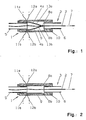
- FIG. 1 and 2 To explain the inventive. Method and the associated jet loom according to a first embodiment of the invention, only the associated clamping device 1 is shown in Figures 1 and 2. It is located in a mixing tube 3.
- the mixing tube 3 connects to the injector of a Hauptblasdüse, not shown in Figure 1, which is located in the illustration of Figure 1 to the left of the mixing tube.
- the injector is used to enter a weft thread 2 by means of blowing air in the shed, which is also not shown in Figure 1 and is located to the right of the mixing tube 3. Before entering the shed, the weft thread 2 is clamped by means of the clamping device 1 in the mixing tube 3.
- the clamping device 1 is arranged between a first mixing pipe section 5 and a second mixing pipe section 6. It has two diametrically opposite on the first mixing tube section 5 arranged lamellar clamping parts 4a, b made of elastic material.
- the free ends 8a, b of the lamellar clamping parts 4a, b are aligned in the insertion direction of the weft thread according to the directional arrow 7 and clamp the weft thread 2 between the mixing pipe sections 5,6 approximately in the plane of the longitudinal center axis of the mixing tube.
- Both clamping parts 4a, b are associated with controllable means.
- the piezoelectric means consist of piezo elements 13a, b, which are connected to the lamellar clamping parts 4a, b.
- the lamellar parts can also be designed as piezo elements themselves.
- the piezo elements 13a, b of the respective lamellar clamping part 4a, b are electrically actuated via lines 11a, b and 12a, b for clamping and releasing the weft thread 2.
- the two lamellar clamping parts 4a, b are enclosed by a chamber 9.
- the housing 10 of the chamber 9 connects the first mixing pipe section 5 axially with the second mixing pipe section 6.
- the lines 11 a, b and 12 a, b to the piezo elements 13 a, b are guided through the housing 10.
- Clamping device 1 between a first mixing pipe section 5 and a second mixing pipe section 6 of the mixing tube 3, wherein the connection takes place axially through the housing 10 of a chamber 9.
- At the first mixing pipe section 5 are again diametrically opposed to each other two lamellar-shaped clamping members 4 a, b arranged from resilient material.
- magnetically-energized magnetic means are provided as magnetic coils 14a, b.
- the operating principle of the clamping device 1 according to FIGS. 3 and 4 is based on the fact that the lamellar clamping parts 4a, b hold the weft thread 2 in a clamping manner due to their spring restoring force when the two magnet coils 14a, b are de-energized (FIG. To release the weft yarn 2, the magnetic forces of the coils 14a, b must overcome the spring restoring force of at least one of the lamellar clamping parts 4a, b and keep the clamping device 1 open for a predetermined period of time.
- the clamping device 1 thus comprises a mixing tube 3 with a first mixing tube section 5 and a second mixing tube section 6.
- the two mixing tube sections 5, 6 are axially connected to one another by the housing 10 of a chamber 9.
- two lamellar clamping parts 4a, b are again arranged on the first mixing pipe section 5.
- the free ends 8 a, b of the clamping parts 4 a, b protrude in the direction of the weft insertion (directional arrow 7) into the chamber 9.
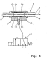
- a central closure in the form of a pneumatic or hydraulic muscle 15 is arranged in the chamber 9 and a central closure in the form of a pneumatic or hydraulic muscle 15 is arranged. It consists of a flexible and elastic material and pressure-tight connects the two mixing pipe sections 5 and 6 with each other.
- the two blade-like clamping parts 4a, b are integrated in the pneumatic or hydraulic muscle and exert on him a spring restoring force that holds the muscle in its initial position. This is shown in Figure 6 and causes the release position in which the weft thread 2 is not clamped.
- the housing 10 of the chamber 9 furthermore has a pressure medium connection 16 which communicates via pressure medium lines 19, 20 and a directional control valve 17 with a pressure source 18.
- FIGS. 5 and 6 The illustration of FIGS. 5 and 6 is rather schematic.
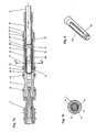
- FIGS. 7a, 7b and 8 show how a clamping device belonging to the invention is realized by technical means.
- Figure 7a shows a longitudinal section through the Hauptblasdüse with a part 5, which acts as a first mixing pipe section 5 and the second mixing pipe section 6.
- a separate housing 10 is omitted for the chamber 9. Rather, the chamber for the pneumatic or hydraulic muscle as part of the first mixing pipe section 5 is formed.
- the second mixing pipe section 6 is a tube on which a coupling sleeve 21 is rotatable and displaceable.
- the coupling sleeve consists in the illustrated embodiment of a plastic and is provided with a threaded portion on which there is an external thread (at 23). With this external thread, the coupling sleeve 21 engages in a receiving opening 22 of the first mixing pipe section 5, which has an enlarged diameter in this area.
- the screw connection between the receiving opening 22 and the coupling sleeve 21 is designated.
- the coupling sleeve 21 has outside a polygonal section, which serves for applying a tool during rotation of the coupling sleeve 21.
- the Polygonal section can be formed for example by flats 40 on an otherwise cylindrical part, see. Fig. 9.
- the clamping device is used with the pneumatic or hydraulic muscle already described.
- the clamping device is designed here in the form of a cartridge. This cartridge consists of the cartridge cage 25, the lamellar clamping parts 4a, b and the tube 31, which serves here as a pneumatic or hydraulic muscle.
- the cartridge cage 25 initially has a short cylindrical guide collar 26, with which it is guided inside in the first mixing tube section 5. Subsequent to the cylindrical guide collar 26 is followed by a first cone 27, which then merges into an elongated cylindrical central portion 28. To the cylindrical central part, a second cone 29 connects. In the cylindrical central portion 28 diametrically opposite two longitudinal slots 30a, b are excluded. In alignment with these longitudinal slots, the two lamellar clamping parts 4a, b are fastened in the remaining area of the cylindrical guide collar. They consist of resilient metal tongues, in any case of a wear-resistant metallic material.
- the lamellar clamping parts 4a, b are narrower than the longitudinal slots 30a, b and can thus be pushed inwardly in the direction of the longitudinal central axis of the cartridge cage through the longitudinal slots. However, under the influence of their spring restoring force, the lamellar clamping parts 4a, b assume a straight-line extended position running parallel to the outer circumference of the cylindrical middle part 28.
- Figure 7b shows that the hose 31 with dissolved clamping device a radial distance from the resilient clamping parts 4a, b complies. This is true at least over most of the width of the clamping parts.
- the lamellar clamping parts are at most with their longitudinal edges slightly on the hose. Since a flat contact of hose and lamellenartigem clamping part is avoided in this way, even a "sticking" of the lamellar clamping parts on the hose does not materialize. As a result, hysteresis phenomena are avoided, and the lamellar clamping parts can be controlled very accurately in time from the release position to the clamping position and vice versa.
- the tube 31 for example, a cylindrical piece of silicone tubing, on the first cone, the cylindrical center part and the second cone on the cartridge cage 25 is pushed. It is then located at a radial distance from the lamellar clamping parts 4a, b.
- the cartridge cage 25 is then inserted - in Figure 7a - in the direction from right to left in the chamber 9 of the first mixing tube section 5 until the cylindrical guide collar engages in a customized cylindrical recess in the first mixing tube section 5.
- the tube 31 covers the first cone 27 and the second cone 29 and is pressed by this against corresponding conical recesses in the first mixing tube section 5.
- a contact pressure is achieved by tightening the coupling sleeve 21, which presses the cartridge cage 25 inwards with the interposition of a sealing ring 24.
- the axial pressing the cartridge cage inwardly into the first mixing tube section causes a sealing compression of the tube 31 in the region of the two cones 27 and 29.
- the cartridge cage 29 is pressed against the end of the second mixing tube section 6, so that this non-rotatably and immovably in the first Mixture pipe section 5 is held.
- the clamping device is now ready for operation.
- the tube 31 is compressed in the chamber 9. He thus applies inwardly to the lamellar clamping parts 4a, b and presses their free ends 8a, b inwardly in the direction of the longitudinal central axis of the mixing tube. A weft thread located in the mixing tube is thereby held in a clamping manner.
- O-rings are referred to, which allow a sealing insertion into a built-in module 30 of the jet looms.
- 35 of the injector located in front of the mixing tube is referred to, which is in two parts in the illustrated embodiment.
- FIGS. 7a, 7b and 8 The advantage of the construction shown in FIGS. 7a, 7b and 8 is that the cartridge consisting of the cartridge cage, the lamellar clamping parts 4a, b and the hose 30 can be quickly removed or replaced at any time. For this purpose, only the coupling sleeve 21 needs to be unscrewed. In the case of clogging by dust, lint or in the case of wear of the lamellar clamping parts can thus be quickly remedied.
- FIG. 8 shows particularly clearly that the cartridge is a compact and relatively simply constructed component.
- FIG. 9 shows in a three-dimensional representation how a plurality of units consisting of injector 35, mixing tube 3 and clamping device 1 can be combined in groups. According to FIG. 9, six such units are combined.
- a built-in module 36 which includes a base part 37 and a mounting plate 38.
- the base part 37 is provided for this purpose with six insertion holes 43 into which the injectors 35 and the injector facing the beginning of the mixing tube is inserted sealingly.
- the mixing tube 3 also consists here of the part of the main blowing nozzle and the second mixing pipe section 6 formed as the first mixing pipe section 5.
- the clamping device 1 in the end region of the first mixing pipe section 5 is inserted in the form of the above-described cartridge with two resilient clamping parts and a pneumatic or hydraulic muscle , Furthermore, it can be seen in FIG. 9 that the coupling sleeves 21 are provided with flats 40, which facilitate the attachment of a tool for rotating the coupling sleeves.
- Figures 10 and 11 show further details of the built-in modules and their installations, in particular details for the supply of the print media.
- the embodiment shown is mainly for air jet looms with pneumatic actuation of the clamping device in question.
- branch channels 39 and annular channels 42 are provided, with which the compressed air or holding air for the weft threads is supplied to the injectors and the mixing tubes.
- 16 again the already explained with reference to Figures 5 and 6 compressed air connection for the operation of the pneumatic muscle is called.
- the O-ring 33 is a separation of those air streams to be supplied to the injector, of those that serve to control the clamping device 1.
Abstract
Description
Die Erfindung betrifft ein Verfahren zum Halten und Freigeben eines Schussfadens im Bereich der Hauptblasdüse einer Düsenwebmaschine, insbesondere Luftdüsenwebmaschine, wobei der Schussfaden vor seinem Eintrag in ein durch Kettfäden gebildetes Webfach in Eintragsrichtung nach einem Injektor der Hauptblasdüse geklemmt und erst kurz vor seinem Eintrag freigegeben wird.The invention relates to a method for holding and releasing a weft thread in the region of the main blowing nozzle of a jet loom, in particular air jet loom, wherein the weft is clamped before its entry in a shed formed by warp sheds in the direction of entry to an injector of the Hauptblasdüse and released shortly before its entry.
Die Erfindung betrifft auch eine Düsenwebmaschine, insbesondere Luftdüsenwebmaschine mit mehrfarbigem Schusseintrag zur Durchführung des Verfahrens, mit zumindest einer Hauptblasdüse, umfassend einen Injektor mit anschließendem Mischrohr, und mit einer Klemmeinrichtung zum Klemmen eines Schussfadens im Mischrohr oder unmittelbar an der Austrittsöffnung des Mischrohrs.The invention also relates to a jet loom, in particular air jet loom with multicolor weft insertion for carrying out the method, with at least one Hauptblasdüse comprising an injector with subsequent mixing tube, and with a clamping device for clamping a weft thread in the mixing tube or directly at the outlet opening of the mixing tube.
Aus der DE 32 00 638 A1 gehen ein Verfahren und eine Düsenwebmaschine dieser Art als bekannt hervor. Dabei schließt an die Hauptblasdüse ein Mischrohr an, in dem sich eine Klemmeinrichtung zum Klemmen des Schussfadens befindet. Die Klemmeinrichtung ist im Bereich des Austrittsendes des Mischrohres angeordnet, in dem der Schussfaden in das Webfach übertritt. Die Klemmeinrichtung kann in einem Schieber bestehen, der quer zur Längsrichtung des Mischrohres als Huborgan verschiebbar ist und den im Mischrohr befindlichen Schussfaden zwischen der Durchtrittsöffnung des Schiebers und der Innenwand des Mischrohres einklemmt. Eine andere Ausführung sieht einen quer verschiebbaren Stempel vor, der den Schussfaden an die Innenwand des Mischrohres drückt. Schließlich ist noch eine weitere Ausführungsform der bekannten Klemmeinrichtung vorgesehen, wonach ein Teilbereich des Mischrohres als elastisches Zwischenstück ausgebildet ist. Das Zwischenstück soll durch zwei einander diametral gegenüberliegende Huborgane zusammengedrückt werden, wenn diese gegeneinander bewegt werden. Der Schussfaden wird dabei durch das zusammengedrückte elastische Zwischenstück eingeklemmt.DE 32 00 638 A1 discloses a method and a jet loom of this type as known. In this case, connects to the Hauptblasdüse a mixing tube in which there is a clamping device for clamping the weft thread. The clamping device is arranged in the region of the outlet end of the mixing tube, in which the weft thread passes into the shed. The clamping device may consist of a slide which is displaceable transversely to the longitudinal direction of the mixing tube as a lifting member and clamps the weft thread located in the mixing tube between the passage opening of the slide and the inner wall of the mixing tube. Another embodiment provides a transversely displaceable punch which presses the weft thread against the inner wall of the mixing tube. Finally, a further embodiment of the known clamping device is provided, according to which a portion of the mixing tube is formed as an elastic intermediate piece. The intermediate piece is to be compressed by two diametrically opposed lifting members, when they are moved against each other. The weft thread is clamped by the compressed elastic intermediate piece.
Bei der ersten und der zweiten Ausführungsform der Klemmeinrichtung dieser bekannten Luftdüsenwebmaschine wird der Schussfaden beim Klemmen seitlich verlagert, befindet sich also nicht mehr in der Mittellängsachse des Mischrohres. Auch bei der dritten Ausführungsform ist diese Erscheinung zu befürchten, weil nur zwei Huborgane zum Zusammendrücken des elastischen Zwischenstücks vorgesehen sind, das Zusammendrücken also nicht streng zentralsymmetrisch erfolgen kann. Eine Lage des Schussfadens außerhalb der Längsmitte des Mischrohres bereitet Schwierigkeiten beim anschließenden Eintrag des Schussfadens in das Webfach.In the first and the second embodiment of the clamping device of this known air-jet weaving machine, the weft thread is displaced laterally during clamping, that is no longer in the central longitudinal axis of the mixing tube. Also in the third embodiment, this phenomenon is to be feared because only two lifting members are provided for compressing the elastic intermediate piece, the compression is therefore not strict can be centrally symmetric. A position of the weft thread outside the longitudinal center of the mixing tube prepares difficulties in the subsequent entry of the weft thread in the shed.
Allen Varianten der Klemmeinrichtung der bekannten Luftdüsenwebmaschine gemäss der DE 32 00 638 A1 ist gemeinsam, dass die Klemmeinrichtung aus mechanischen Stellgliedern besteht und mechanisch betätigt werden muss. Ein mechanischer Antrieb erfordert einen gewissen Einbauraum und kann nicht erschütterungsfrei arbeiten. Es wird zu diesem Stand der Technik auch schon kritisch auf die Möglichkeit von unkontrollierten Schwenkbewegungen hingewiesen, die das freie Ende des Mischrohres beim Betätigen der Fadenklemme durchführen kann. Da insbesondere bei mehrfarbigem Schusseintrag der zur Verfügung stehende Raum für eine größere Anzahl von dicht nebeneinander angeordneten Mischrohren sehr begrenzt ist, kann die bekannte Lösung nicht ohne weiteres in der Praxis durchführbar sein. Zudem schaden mechanische Schwingungen oder Erschütterungen der Mischrohre der präzisen Funktion derartiger Düsenwebmaschinen.All variants of the clamping device of the known air jet loom according to
Die EP 0 022 226 B1 behandelt eine andere bekannte Düsenwebmaschine, bei der ebenfalls eine mechanische Klemmeinrichtung mit einem mechanischen Antrieb vorgesehen ist. Unmittelbar am Ende des Mischrohres befindet sich eine feste Auflage, an der der einzutragende Schussfaden vorbeigleitet. Ferner ist eine Spiralfeder angeordnet, deren inneres Ende durch eine Achse verdreht wird, die parallel zur Achse des Mischrohrs verläuft. Die Spirale wird also in einer Ebene quer zum Schussfaden verspannt. Dabei drückt ihr freies Ende elastisch nachgiebig den Schussfaden gegen die erwähnte feste Auflage. Die Achse, welche die Spirale verdreht, wird mittels zweier Drehhebel über eine fest mit dem Maschinenrahmen verbundene Welle angetrieben. Mit dieser Klemmeinrichtung wird der Schussfaden nach Beendigung des Schusseintrages und vor dem Abschneiden des eingetragenen Schussfadens festgehalten und zu Beginn des nächsten Schusseintrags wieder freigegeben.EP 0 022 226 B1 deals with another known jet loom in which a mechanical clamping device is also provided with a mechanical drive. Immediately at the end of the mixing tube is a solid support on which slides in the weft thread passes. Further, a spiral spring is arranged, whose inner end is rotated by an axis which is parallel to the axis of the mixing tube. The spiral is thus clamped in a plane transverse to the weft. Her free end presses elastically yielding the weft against the mentioned solid support. The axis which rotates the spiral is driven by means of two rotary levers via a shaft fixedly connected to the machine frame. With this clamping device, the weft thread is retained after completion of the weft insertion and before the cutting of the inserted weft thread and released again at the beginning of the next weft insertion.
Die bekannte Klemmeinrichtung gemäß der EP 0 022 226 B1 hat verschiedene Schwachpunkte. Wenn nämlich das federnde Ende der Spirale nur mit leichtem Druck den Schussfaden gegen die feste Auflagefläche drückt, so wird zwar der Faden geschont. Aber es besteht die Gefahr, dass das federnde Ende der Spirale seitlich mitgenommen und auf die Dauer verbogen wird. Bei einer stabileren Ausführung des federnden Endes oder einer soliden Führung der gesamten Spirale ist dagegen zu befürchten, dass der Schussfaden beim Klemmen beschädigt wird. Hinzu kommt noch, dass auch bei dieser Ausführung eine zentrale Führung des Schussfadens in der Längsachse des Mischrohres nicht gewährleistet ist.The known clamping device according to EP 0 022 226 B1 has several weak points. Namely, if the resilient end of the spiral pushes the weft yarn against the solid support surface only with slight pressure, so the yarn is spared. But there is a risk that the resilient end of the spiral will be taken laterally and bent over time. In a more stable design of the resilient end or a solid guide the entire spiral, however, is to be feared that the weft thread is damaged during clamping. In addition, even in this embodiment, a central guidance of the weft thread in the longitudinal axis of the mixing tube is not guaranteed.
Entweder muss nämlich der Schussfaden ständig an der Auflage anliegen, so dass dieser dauernd einer Gleit- und Scheuerbeanspruchung ausgesetzt ist. Oder es besteht ein größerer Abstand zwischen der festen Auflagefläche und dem Schussfaden, dann wird der Schussfaden aber beim Klemmen deutlich seitlich verlagert. Die mechanische Betätigung mittels einer gesonderten Antriebswelle und zweier Drehhebel erfordert zudem sehr viel Platz und kann nicht erschütterungsfrei arbeiten. Eine Mehrfachanordnung von mehreren Hauptblasdüsen und Mischrohren ist daher nur schwer vorstellbar. Ganz sicher sind bei einem derartigen Antrieb Erschütterungen und Querschwingungen unvermeidlich. Eine Steuerung mittels einer Drehwelle ist zudem bauaufwendig.Either the weft thread must constantly rest against the support, so that it is constantly exposed to sliding and abrasion stress. Or there is a greater distance between the fixed support surface and the weft thread, but then the weft thread is displaced significantly laterally during clamping. The mechanical operation by means of a separate drive shaft and two rotary lever also requires a lot of space and can not work vibration-free. A multiple arrangement of several main blowing nozzles and mixing tubes is therefore difficult to imagine. Quite certainly vibrations and transverse vibrations are inevitable in such a drive. A control by means of a rotary shaft is also expensive to build.
Es gehört auch zum fachmännischen Wissen, den Schussfaden im Mischrohr allein durch Halteluft gestreckt zu halten. Dies ist eine sichere Methode, um den Schussfaden genau in der Längsmitte des Mischrohres zu führen, so dass er eine optimale Position für das anschließende Eintragen in das Webfach hat. Da insbesondere beim Weben von Mustern ein einzelner Schussfaden oft längere Zeitintervalle im Mischrohr zu halten ist, erfordert diese Methode, den Schussfaden zu halten, einen dauernden Strom von Halteluft und damit einen erheblichen Energieaufwand. Zudem ist festgestellt worden, dass bestimmte Garne durch das Halten mittels Halteluft modifiziert, d. h. in ihren Eigenschaften nachteilig verändert werden.It is also part of the expert knowledge to keep the weft in the mixing tube stretched by holding air alone. This is a safe method to guide the weft exactly in the longitudinal center of the mixing tube, so that it has an optimal position for subsequent entry into the shed. Since, in particular, when weaving patterns a single weft thread is often to hold longer time intervals in the mixing tube, this method requires to keep the weft thread, a continuous stream of holding air and thus a considerable expenditure of energy. In addition, it has been found that certain yarns are modified by hold-up hold, i. H. be adversely affected in their properties.
Der Erfindung liegt daher die Aufgabe zugrunde, dass eingangs genannte Verfahren und die genannte Düsenwebmaschine derart abzuwandeln, dass es möglich wird, den Schussfaden mit möglichst wenig oder ohne jede Halteluft hinter dem Injektor auf schonende Weise und zentral gestreckt zu halten, wobei eine raumsparende und möglichst erschütterungsfreie Bauweise mit kompakter Mehrfachanordnung von Hauptblasdüsen und Mischrohren möglich wird und die Halteeinrichtung über längere Betriebszeiten verschleißfrei und zuverlässig arbeitet.The invention is therefore the object of the above-mentioned method and said jet loom to modify such that it is possible to keep the weft with as little or no holding air behind the injector in a gentle way and centrally stretched, with a space-saving and possible vibration-free design with a compact multiple arrangement of Hauptblasdüsen and mixing tubes is possible and the holding device works wear-free and reliable over long periods of operation.
Die Lösung dieser Aufgabe hinsichtlich des Verfahrens erfolgt durch die Merkmale des Anspruchs 1. Zu diesem Verfahren gehörende vorteilhafte Ausgestaltungen sind in den Ansprüchen 2 bis 6 angegeben.The solution of this problem with regard to the method is carried out by the features of
Hinsichtlich der Düsenwebmaschine ist die Lösung der genannten Aufgabe im Anspruch 7 enthalten. Vorteilhafte Ausgestaltungen dieser erfindungsgemäßen Düsenwebmaschine sind Gegenstand der Ansprüche 8 bis 25.With regard to the jet loom, the solution of the stated object is contained in
Schließlich gehört zu der Erfindung auch eine in den Ansprüchen 26 bis 28 angegebene Kartusche als auswechselbare Baueinheit zum Einsetzen in das Mischrohr einer Düsenwebmaschine. Diese erfindungsgemäße Kartusche baut auf vorteilhaften konstruktiven Einzelheiten auf, die die erfindungsgemäße Düsenwebmaschine kennzeichnen.Finally, the invention also includes a specified in the
Die erfindungsgemäße Lösung hinsichtlich des Verfahrens besteht somit gemäß Anspruch 1 in einem Verfahren zum Halten und Freigeben eines Schussfadens im Bereich der Hauptblasdüse einer Düsenwebmaschine, insbesondere Luftdüsenwebmaschine, wobei der Schussfaden vor seinem Eintrag in ein durch Kettfäden gebildetes Webfach in Eintragsrichtung nach einem Injektor der Hauptblasdüse geklemmt und erst kurz vor seinem Eintrag freigegeben wird, und wobei das Klemmen und Freigeben des Schussfadens durch die sich federnd gegeneinander legenden, in der Eintragsrichtung des Schussfadens ausgerichteten freien Enden zweier lamellenartiger Klemmteile erfolgt, von denen wenigstens ein lamellenartiges Klemmteil in seiner Lage durch steuerbare Mittel gegenüber dem anderen lamellenartigen Klemmteil verstellbar ist.The solution according to the invention with regard to the method thus consists according to
Die erfindungsgemäß vorgesehenen lamellenartigen Klemmteile, deren freie Enden sich federnd gegeneinander legen und in der Eintragsrichtung des Schussfadens ausgerichtet sind, bilden zuverlässige Klemmteile von geringer Masse, die sich trägheitsarm und exakt steuern lassen. Infolge der Ausrichtung ihrer freien Enden in der Eintragsrichtung des Schussfadens werden sie in ihrer Längsrichtung und damit statisch günstig beansprucht, so dass sie auch bei leichter Ausführung eine erhebliche Klemmkraft ausüben können. Zudem kommt bei einer Ausrichtung in Längsrichtung des Schussfadens eine selbstzentrierende Wirkung zustande, weil der Schussfaden gewissermaßen selbst die lamellenartigen Klemmteile in die Mitte der Längsachse des Mischrohres zieht. Die lamellenartigen Klemmteile sind zudem mit einfachen Mitteln zu steuern. Da die bewegten Massen der Klemmteile sehr gering sind, ergeben sich auch keine Querschwingungen oder andere mechanische Erschütterungen.The inventively provided lamellar clamping parts whose free ends are resiliently against each other and are aligned in the insertion direction of the weft thread, form reliable clamping parts of low mass, which can be controlled inertia and precise. As a result of the orientation of their free ends in the insertion direction of the weft yarn they are stressed in their longitudinal direction and thus statically favorable, so that they can exert a considerable clamping force even with a lighter design. In addition, when aligned in the longitudinal direction of the weft yarn, a self-centering effect is achieved, because the weft thread, so to speak, pulls the lamellar clamping parts into the middle of the longitudinal axis of the mixing tube. The lamellar clamping parts are also controlled by simple means. Since the moving masses of the clamping parts are very small, there are no transverse vibrations or other mechanical shocks.
Zu ihrer Steuerung können die lamellenartigen Klemmteile mit piezoelektrischen Mitteln verbunden sein. Oder die Verstellbarkeit kann durch die Kraft wenigstens eines auf ein lamellenartiges Klemmteil wirkenden elektromagnetischen Mittels erreicht werden.For their control, the lamellar clamp members may be connected by piezoelectric means. Or the adjustability can be achieved by the force of at least one acting on a lamellar clamping member electromagnetic means.
Die beiden genannten Mittel zum Verstellen der lamellenartigen Klemmteile lassen eine exakte und dennoch kompakte Ausführung der Steuerungseinrichtung zu.The two mentioned means for adjusting the lamellar clamping parts allow an exact yet compact design of the control device.
Eine bevorzugte erfindungsgemäße Lösung hinsichtlich des Verfahrens gemäß Anspruch 1 besteht demgegenüber in einem Verfahren zum Halten und Freigeben eines Schussfadens im Bereich der Hauptblasdüse einer Düsenwebmaschine, insbesondere Luftdüsenwebmaschine, wobei der Schussfaden vor seinem Eintrag in ein durch Kettfäden gebildetes Webfach in Eintragsrichtungen nach einem Injektor der Hauptblasdüse geklemmt und erst kurz vor seinem Eintrag freigegeben wird, und wobei das Klemmen und Freigeben des Schussfadens durch die in der Eintragsrichtung des Schussfadens ausgerichteten Enden von zwei lamellenartigen Klemmteilen erfolgt, die in einen durch ein Druckmedium betätigten pneumatischen oder hydraulischen Muskel integriert sind und auf diesen eine Federrückstellkraft ausüben, wobei nach Maßgabe der Druckbeaufschlagung des pneumatischen oder hydraulischen Muskels dieser entweder die Federrückstellkraft der lamellenartigen Klemmteile überwindet und deren freie in den Muskel hineinragende Enden klemmend gegen den Schussfaden drückt oder das Aufheben der Klemmwirkung zulässt.A preferred solution according to the invention with respect to the method according to
Auch diese erfindungsgemäße Lösung weist somit die schon erwähnten Vorteile auf, die durch die lamellenartigen Klemmteile zustande kommen. Sie werden aber in diesem Fall in einen durch ein Druckmedium betätigten pneumatischen oder hydraulischen Muskel integriert. Während bei der eingangs genannten bekannten Klemmeinrichtung ein flexibler und elastischer Rohrabschnitt die Klemmung bewirkt und von außen durch mechanische Glieder betätigt wird, ist bei der Erfindung vorgesehen, dass ein flexibles und elastisches Glied, nämlich der pneumatische oder hydraulische Muskel, die mechanischen Glieder, nämlich die lamellenartigen Klemmteile, verstellt, wenn ein Druckmedium auf den Muskel einwirkt. Im Gegensatz zu der bekannten Lösung kommt hierdurch eine besonders verschleißarme Betriebsweise zustande, weil der Schussfaden nicht mehr mit einem elastischen Wandteil zusammenwirkt, sondern mit den lamellenartigen Klemmteilen, die viel besser der unvermeidlichen Reibung an dem Schussfaden gewachsen sind. Durch die Steuerung mittels eines Druckmediums, insbesondere durch Druckluft, ergeben sich weitere Vorteile hinsichtlich der Steuerung der gesamten Maschine, insbesondere bei Luftdüsenwebmaschinen, bei denen ohnehin Druckluft zur Verfügung steht.Also, this solution according to the invention thus has the already mentioned advantages that come about through the lamellar clamping parts. However, in this case they are integrated into a pneumatic or hydraulic muscle actuated by a pressure medium. While in the above-mentioned known clamping device, a flexible and elastic pipe section causes the clamping and is actuated from the outside by mechanical members, is provided in the invention that a flexible and elastic member, namely the pneumatic or hydraulic muscle, the mechanical members, namely lamellar clamping parts, adjusted when a pressure medium acts on the muscle. In contrast to the known solution, this results in a particularly low-wear mode of operation, because the weft thread no longer cooperates with an elastic wall part, but with the lamellar clamping parts, which are much better the inevitable friction grown on the weft. By controlling by means of a pressure medium, in particular by compressed air, there are further advantages in terms of the control of the entire machine, especially in air jet looms, in which compressed air is available anyway.
Nach einer ersten vorteilhaften Ausgestaltung dieses bevorzugten erfindungsgemäßen Verfahrens wirkt das Druckmedium von außen unter Überdruck auf den pneumatischen oder hydraulischen Muskel ein.According to a first advantageous embodiment of this preferred method according to the invention, the pressure medium acts from the outside under pressure on the pneumatic or hydraulic muscle.
Zur beschleunigten Aufhebung der Klemmwirkung kann aber zusätzlich vorgesehen sein, dass der pneumatische oder hydraulische Muskel von außen gesteuert unter Unterdruck gesetzt und/oder von innen mit Überdruck beaufschlagt wird. Die Klemmwirkung wird dabei sehr schnell aufgehoben, so dass unnötige Reibungserscheinungen zwischen dem Schussfaden einerseits und den lamellenartigen Klemmteilen oder dem Muskel selber andererseits vermieden sind.For accelerated cancellation of the clamping effect but can also be provided that the pneumatic or hydraulic muscle controlled from the outside under negative pressure and / or is pressurized from the inside with overpressure. The clamping effect is canceled very quickly, so that unnecessary friction phenomena between the weft on the one hand and the lamellar clamping parts or the muscle itself are avoided on the other hand.
Die dem erfindungsgemäßen Verfahren entsprechende Düsenwebmaschine ist in dem Anspruch 7 angegeben. Dieser betrifft somit eine Düsenwebmaschine, insbesondere Luftdüsenwebmaschine mit mehrfarbigem Schusseintrag zur Durchführung des Verfahrens nach einem der Ansprüche 1 bis 6, mit zumindest einer Hauptblasdüse, umfassend einen Injektor mit anschließendem Mischrohr, mit einer Klemmeinrichtung zum Klemmen eines Schussfadens im Mischrohr oder unmittelbar an der Austrittsöffnung des Mischrohrs, wobei die Klemmeinrichtung zwei lamellenartige Klemmteile aufweist, deren freie, in der Eintragsrichtung des Schussfadens ausgerichtete Enden sich federnd gegeneinander legen und den Schussfaden zwischen sich führen, und mit Steuereinrichtungen, durch die die Lage wenigstens eines der beiden lamellenartigen Klemmteile gegenüber dem anderen lamellenartigen Klemmteil verstellbar ist.The method according to the invention corresponding jet loom is specified in the
Vorteilhafte Ausgestaltungen dieser erfindungsgemäßen Düsenwebmaschine sind in den Ansprüchen 8 bis 15 angegeben. Die in diesen Ansprüchen vorgeschriebene Steuerung der leichten lamellenartigen Klemmteile, deren freie, in der Eintragsrichtung des Schussfadens ausgerichtete Enden sich federnd gegeneinander legen und den Schussfaden zwischen sich führen, lassen sich vorteilhaft mit einer piezoelektrischen Steuereinrichtung oder einer magnetischen Steuereinrichtung verstellen. Ersichtlich können derartige Steuereinrichtungen sehr trägheitsarm und zeitgenau arbeiten, wobei zudem ihr Bauaufwand und Raumbedarf sehr gering ist. Die Klemmeinrichtung mit piezoelektrischer oder magnetischer Steuerung ist daher für die Mehrfachanordnung in Luftdüsenwebmaschinen zum Weben von Mustern besonders geeignet.Advantageous embodiments of this jet loom according to the invention are specified in claims 8 to 15. The prescribed in these claims control of the light lamellar clamping parts, the free, aligned in the insertion direction of the weft yarn ends resiliently against each other and lead the weft thread between them, can be advantageously adjusted with a piezoelectric control device or a magnetic control device. Obviously, such control devices can work very low in inertia and time, and also their construction cost and space requirements is very low. The clamping device with piezoelectric or magnetic control is therefore particularly suitable for the multiple arrangement in air jet looms for weaving patterns.
Die dem Verfahren gemäß dem Anspruch 4 entsprechende bevorzugte erfindungsgemäße Düsenwebmaschine ist Gegenstand des Anspruchs 16. Dieser umfasst somit eine Düsenwebmaschine, mit einer Hauptblasdüse, umfassend einen Injektor mit anschließendem Mischrohr, mit einer Klemmeinrichtung für den Schussfaden, die als Zentralverschluss mit einem pneumatischen oder hydraulischen Muskel ausgebildet und im Mischrohr oder unmittelbar an der Austrittsöffnung des Mischrohrs angeordnet ist, mit einer den pneumatischen oder hydraulischen Muskel umgebenden Kammer, die durch ein Druckmedium beaufschlagbar ist, und mit zwei in den pneumatischen oder hydraulischen Muskel integrierten lamellenartigen Klemmteilen aus federelastischem Material, zwischen deren freien, in die Eintragsrichtung des Schussfadens ausgerichteten Enden der Schussfaden geführt ist, und zwar in derartiger Anordnung, dass nach Maßgabe der Druckbeaufschlagung des pneumatischen oder hydraulischen Muskels dieser entweder die Federrückstellkraft der lamellenartigen Klemmteile überwindet und deren freie in den Muskel hineinragende Enden klemmend gegen den Schussfaden drückt oder das Aufheben der Klemmwirkung unter der Wirkung der Federrückstellkraft zulässt.The method according to claim 4 corresponding preferred jet loom according to the invention is the subject of
Wie schon beim Verfahren gemäß Anspruch 4 erläutert worden ist, werden hier die Vorteile eines pneumatischen oder hydraulischen Muskels, also eines elastischen Wandabschnittes des Mischrohres, mit denen einer Steuerung durch ein Druckmedium verbunden, wobei auch noch die Vorteile der in den pneumatischen oder hydraulischen Muskel integrierten lamellenartigen Klemmteile hinzukommen. Das unmittelbare Zusammenwirken mit dem Schussfaden erfolgt über die lamellenartigen Klemmteile, die dem Verschleiß durch Reibung am besten gewachsen sind. Sie können durch den pneumatischen oder hydraulischen Muskel sehr vorteilhaft gesteuert werden, wobei insbesondere bei einer Steuerung mittels Druckluft in der Luftdüsenwebmaschine eine kombinierte Gesamtsteuerung allein durch Druckluft möglich ist und zu einer kompakten und nicht zu aufwendigen Bauweise führt. Durch die Integration der lamellenartigen Klemmteile in den Muskel wird dessen Lebensdauer erheblich verlängert.As has already been explained in the method according to claim 4, the advantages of a pneumatic or hydraulic muscle, so an elastic wall portion of the mixing tube, with which a controller connected by a pressure medium, where also the benefits of integrated into the pneumatic or hydraulic muscle added to lamellar clamping parts. The immediate interaction with the weft thread via the lamellar clamping parts, which are best grown by friction wear. They can be controlled very advantageously by the pneumatic or hydraulic muscle, in particular in a control by means of compressed air in the air jet loom, a combined overall control is possible only by compressed air and leads to a compact and not too expensive construction. Through the integration of the lamellar clamping parts in the muscle whose life is considerably extended.
Die Gestaltung der lamellenartigen Klemmteile wird in der Regel derart sein, dass die Klemmteile im unbeeinflussten Zustand eine gestreckte Stellung parallel zur Längsachse des Mischrohres einnehmen. Wird aber der pneumatische oder hydraulische Muskel durch ein Druckmedium zusammengedrückt, so werden die freien Enden der lamellenartigen Klemmteile nach innen gegen den Schussfaden gedrückt. Im einfachsten Fall reicht es aus, wenn nur eines der beiden Klemmteile verlagert wird, wobei sich allerdings eine seitliche Verlagerung des Schussfadens ergibt.The design of the lamellar clamping parts will usually be such that the clamping parts assume an extended position parallel to the longitudinal axis of the mixing tube in the uninfluenced state. But if the pneumatic or hydraulic muscle is compressed by a pressure medium, the free ends of the lamellar clamping parts are pressed inwards against the weft. In the simplest case, it is sufficient if only one of the two clamping parts is displaced, but that results in a lateral displacement of the weft thread.
Es kommt eine nahezu punktweise Berührung der freien Enden der lamellenartigen Klemmteile zustande, wobei sich zwischen ihnen der Schussfaden befindet. Da die lamellenartigen Klemmteile aus federelastischem Material bestehen, bleibt ihre Andrückwirkung an den Schussfaden elastisch nachgiebig, so dass eine zu starke Beanspruchung des Schussfadens ausgeschlossen ist.There is an almost point contact with the free ends of the lamellar clamping parts, with the weft thread between them. Since the lamellar clamping parts are made of resilient material, their pressing action on the weft thread remains elastically yielding, so that excessive stress on the weft thread is excluded.
Vorteilhafte konstruktive Ausgestaltungen der erfindungsgemäßen Düsenwebmaschine gemäß Anspruch 15 sind in den Ansprüchen 16 bis 25 angegeben.Advantageous structural embodiments of the jet loom according to the invention according to claim 15 are specified in
So sind die Ansprüche 16 und 17 auf die Möglichkeit gerichtet, dass die den pneumatischen oder hydraulischen Muskel umgebende Kammer durch die einander zugewandten Enden zweier Mischrohrabschnitte gebildet wird, wobei diese Enden mittels einer Kupplungshülse miteinander verschraubt werden.Thus, claims 16 and 17 are directed to the possibility that the surrounding the pneumatic or hydraulic muscle chamber is formed by the facing ends of two mixing pipe sections, said ends being screwed together by means of a coupling sleeve.
Die Ansprüche 18 bis 22 zeigen Einzelheiten auf, nach denen die Klemmeinrichtung in der Kammer in Form eines auswechselbaren Bauteiles ausgeführt werden kann, bei dem auf einen Kartuschenkäfig der pneumatische oder hydraulische Muskel in Form eines Schlauches aufgeschoben wird, der dann auch die beiden an dem Kartuschenkäfig befestigten lamellenartigen Klemmteile überdeckt. Der Kartuschenkäfig weist hierzu Durchbrechungen in Form von Längsschlitzen auf, durch die hindurch die Klemmteile nach innen greifen und der Muskel unter der Einwirkung eines Druckmediums zusammengedrückt wird. Der Kartuschenkäfig hat dabei einen ersten und zweiten Konus, mit denen er unter Zwischenlage des Schlauches an entsprechenden konischen Innenbereichen des ersten Mischrohrabschnittes dichtend anliegt. Mittels der Kupplungshülse wird der Kartuschenkäfig in seiner Längsrichtung axial gegen den ersten Mischrohrabschnitt gespannt, wodurch zugleich die betriebliche Lagesicherung und Abdichtung des zweiten Mischrohrabschnittes gegenüber dem ersten Mischrohrabschnitt erzielt wird.The
Die Ansprüche 23 bis 25 sind darauf gerichtet, mehrere der aus Injektor, Mischrohr und Klemmeinrichtung gemäß Anspruch 15 bestehenden Einheiten gruppenweise zu einem Einbaumodul zusammenzufassen. Indem dabei Stich- und Ringkanäle zur Zufuhr des Druckmediums und zu dem hydraulischen Muskel in dem Einbaumodul ausgebildet werden, ergibt sich auch bei dichter Zusammenfassung dieser Einheiten eine vorteilhafte und kompakte Steuerungsmöglichkeit für den Eintrag der Schussfäden und die Klemmeinrichtungen.
Schließlich sind die Ansprüche 26 bis 28 auf eine Kartusche als auswechselbare Baueinheit zum Einsetzen in das Mischrohr einer Düsenwebmaschine gerichtet, wobei ebenfalls vorteilhafte Ausgestaltungen aufgeführt sind. Die zweite erfindungsgemäße Bauform der Düsenwebmaschine eröffnet nämlich die Möglichkeit, die wesentlichen Teile der Klemmeinrichtung, d.h. die lamellenartigen Klemmteile und den pneumatischen oder hydraulischen Muskel auf dem Kartuschenkäfig als Träger auswechselbar anzuordnen. Das entsprechend gestaltete Bauteil der Kartusche ist daher ein für sich handhabbares wertvolles Ersatz- und Einzelteil, dem erfinderische Bedeutung zukommt.Finally, the
Die Erfindung wird anschließend anhand von in Zeichnungen dargestellten Ausführungsbeispielen noch näher erläutert. In den Zeichnungen ist das Folgende dargestellt:
- Fig. 1
- zeigt ein erstes Ausführungsbeispiel der Erfindung, wobei ein Schussfaden klemmend gehalten ist.
- Fig. 2
- ist eine der Fig.1 entsprechende Darstellung, wobei die Klemmeinrichtung jedoch gelöst ist.
- Fig. 3
- gibt ein weiteres Ausführungsbeispiel der Erfindung wieder, wobei wieder die Klemmstellung gezeigt ist.
- Fig. 4
- ist eine der Fig.3 entsprechende Darstellung bei gelöster Klemmeinrichtung.
- Fig. 5
- hat eine schematische Darstellung derjenigen Ausführungsform der Erfindung zum Gegenstand, bei der die Klemmeinrichtung durch ein Druckmedium betätigt wird.
- Fig. 6
- entspricht dem Schema der Fig.5, jedoch bei gelöster Klemmeinrichtung .
- Fig. 7a
- zeigt im Längsschnitt
eine den Figuren 5 und 6 entsprechende Klemmeinrichtung in detaillierter technischer Ausführung. - Fig. 7b
- ist ein Querschnitt längs der Linie B-B in Fig. 7a
- In Fig. 8
- ist eine Einzelheit aus den Fig.7a und 7b in perspektivischer Darstellung vergrößert herausgezeichnet.
- Fig. 9
- zeigt die gruppenweise Zusammenfassung mehrerer aus Injektor, Mischrohr und Klemmeinrichtung bestehenden Einheiten zu einem Einbaumodul.
- Fig. 10
- ist ein zu Fig. 9 gehörender senkrechter Teillängsschnitt; und
- Fig. 11
- gibt einen, bezogen auf Fig. 9, waagerecht verlaufenden Teillängsschnitt durch ein Einbaumodul wieder.
- Fig. 1
- shows a first embodiment of the invention, wherein a weft thread is held clamped.
- Fig. 2
- is a representation corresponding to Figure 1, wherein the clamping device is solved, however.
- Fig. 3
- is another embodiment of the invention again, again the clamping position is shown.
- Fig. 4
- is a representation corresponding to Figure 3 with dissolved clamping device.
- Fig. 5
- is a schematic representation of that embodiment of the invention in the object in which the clamping device is actuated by a pressure medium.
- Fig. 6
- corresponds to the scheme of Figure 5, but with dissolved clamping device.
- Fig. 7a
- shows in longitudinal section a Figures 5 and 6 corresponding clamping device in detailed technical design.
- Fig. 7b
- is a cross section along the line BB in Fig. 7a
- In Fig. 8
- is a detail of Figures 7a and 7b drawn out in an enlarged perspective view.
- Fig. 9
- shows the groupwise summary of several consisting of injector, mixing tube and clamping units to a built-in module.
- Fig. 10
- is a belonging to Figure 9 vertical partial longitudinal section. and
- Fig. 11
- is one, based on Fig. 9, horizontally extending partial longitudinal section through a built-in module again.
Zur Erläuterung des erfindungsgemäßen. Verfahrens und der zugehörigen Düsenwebmaschine gemäß einer ersten Ausführungsform der Erfindung ist in den Figuren 1 und 2 nur die dazu gehörende Klemmeinrichtung 1 dargestellt. Sie befindet sich in einem Mischrohr 3. Das Mischrohr 3 schließt an den Injektor einer in Fig.1 nicht dargestellten Hauptblasdüse an, die sich in der Darstellung der Fig.1 links von dem Mischrohr befindet. Der Injektor dient zum Eintragen eines Schussfadens 2 mittels Blasluft in das Webfach, das in Fig.1 gleichfalls nicht dargestellt ist und sich rechts vom Mischrohr 3 befindet. Vor dem Eintrag in das Webfach ist der Schussfaden 2 mittels der Klemmeinrichtung 1 in dem Mischrohr 3 klemmend gehalten.To explain the inventive. Method and the associated jet loom according to a first embodiment of the invention, only the associated
Die Klemmeinrichtung 1 ist zwischen einem ersten Mischrohrabschnitt 5 und einem zweiten Mischrohrabschnitt 6 angeordnet. Sie besitzt zwei einander diametral gegenüberliegend am ersten Mischrohrabschnitt 5 angeordnete lamellenartige Klemmteile 4a,b aus federelastischem Material. Die freien Enden 8a,b der lamellenartigen Klemmteile 4a,b sind in der Eintragsrichtung des Schussfadens, entsprechend dem Richtungspfeil 7 ausgerichtet und klemmen den Schussfaden 2 zwischen den Mischrohrabschnitten 5,6 etwa in der Ebene der Längsmittenachse des Mischrohres 3.The
Beiden Klemmteilen 4a,b sind steuerbare Mittel zugeordnet. Im Falle der Figuren 1 und 2 sind das piezoelektrische Mittel. Sie bestehen aus Piezoelementen 13a,b, die mit den lamellenartigen Klemmteilen 4a,b verbunden sind. Die lamellenartigen Teile können aber auch selbst als Piezoelemente ausgebildet sein. Gemäß den Figuren 1 und 2 werden zum Klemmen und Freigeben des Schussfadens 2 die Piezoelemente 13a,b des jeweiligen lamellenartigen Klemmteils 4a,b über Leitungen 11a,b und 12a,b elektrisch angesteuert.Both clamping
Bei der dargestellten Anordnung der Klemmeinrichtung 1 im Mischrohr 3 sind die beiden lamellenartigen Klemmteile 4a,b von einer Kammer 9 umschlossen. Das Gehäuse 10 der Kammer 9 verbindet den ersten Mischrohrabschnitt 5 axial mit dem zweiten Mischrohrabschnitt 6. Die Leitungen 11a,b und 12a,b zu den Piezoelementen 13a,b sind durch das Gehäuse 10 geführt.In the illustrated arrangement of the
Je nach Richtung der an die Piezoelemente 13a,b angelegten Spannung wird erreicht, dass die lamellenartigen Klemmteile 4a,b den Schussfaden 2 klemmend halten (Fig.1) oder freigeben (Fig.2).Depending on the direction of the voltage applied to the piezoelectric elements 13a, b, it is achieved that the
In den Figuren 3 und 4 sind für diejenigen Teile, die im Vergleich zu den Figuren 1 und 2 unverändert sind, dieselben Bezugsziffern wie vorher verwendet. Auch hier befindet sich dieIn Figs. 3 and 4, the same reference numerals are used for those parts which are unchanged from Figs. 1 and 2 as before. Also here is the
Klemmeinrichtung 1 zwischen einem ersten Mischrohrabschnitt 5 und einem zweiten Mischrohrabschnitt 6 des Mischrohres 3, wobei die Verbindung axial durch das Gehäuse 10 einer Kammer 9 erfolgt. An dem ersten Mischrohrabschnitt 5 sind wieder diametral einander gegenüberliegend zwei lamellenartig ausgebildete Klemmteile 4a,b aus federelastischem Material angeordnet. Abweichend von der Ausbildung gemäß den Figuren 1 und 2 sind bei der Ausführung gemäß den Figuren 3 und 4 jedoch als Magnetspulen 14a,b ausgebildete bestrombare magnetische Mittel vorgesehen.Clamping
Das Funktionsprinzip der Klemmeinrichtung 1 gemäß den Figuren 3 und 4 beruht darauf, dass die lamellenartigen Klemmteile 4a,b auf Grund ihrer Federrückstellkraft den Schussfaden 2 klemmend halten, wenn die beiden Magnetspulen 14a,b stromlos sind (Fig.3). Zum Freigeben des Schussfadens 2 müssen die magnetischen Kräfte der Spulen 14a,b die Federrückstellkraft wenigstens eines der lamellenartigen Klemmteile 4a,b überwinden und die Klemmeinrichtung 1 für eine vorbestimmte Zeitdauer offen halten.The operating principle of the
Gemäß den Figuren 5 und 6 wird das der Erfindung zugrunde liegende Problem auf eine nochmals abgewandelte Weise gelöst. Auch hier sind die gegenüber den vorangegangenen Ausführungsbeispielen unverändert gebliebenen Teile mit denselben Bezugsziffern wie vorher bezeichnet. Die Klemmeinrichtung 1 gemäß den Figuren 5 und 6 umfasst somit ein Mischrohr 3 mit einem ersten Mischrohrabschnitt 5 und einem zweiten Mischrohrabschnitt 6. Die beiden Mischrohrabschnitte 5,6 werden durch das Gehäuse 10 einer Kammer 9 axial miteinander verbunden. In der Kammer sind wieder zwei lamellenartige Klemmteile 4a,b an dem ersten Mischrohrabschnitt 5 angeordnet. Die freien Enden 8a,b der Klemmteile 4a,b ragen in der Richtung des Schusseintrags (Richtungspfeil 7) in die Kammer 9.According to Figures 5 and 6, the problem underlying the invention is solved in a further modified manner. Again, with respect to the previous embodiments remained unchanged parts with the same reference numerals as previously designated. The
Abweichend von den vorangegangenen Ausführungsformen ist bei der Klemmeinrichtung 1 gemäß den Figuren 5 und 6 in der Kammer 9 auch ein Zentralverschluss in der Form eines pneumatischen oder hydraulischen Muskels 15 angeordnet. Er besteht aus einem flexiblen und elastischen Material und verbindet druckdicht die beiden Mischrohrabschnitte 5 und 6 miteinander. Die beiden lamellenartigen Klemmteile 4a,b sind in den pneumatischen oder hydraulischen Muskel integriert und üben auf ihn eine Federrückstellkraft aus, die den Muskel in seiner Ausgangslage hält. Diese ist in Fig.6 dargestellt und bewirkt die Freigabestellung, in der der Schussfaden 2 nicht geklemmt ist.Notwithstanding the preceding embodiments, in the
Das Gehäuse 10 der Kammer 9 weist femer einen Druckmittelanschluss 16 auf, der über Druckmittelleitungen 19,20 und ein Wegeventil 17 mit einer Druckquelle 18 in Verbindung steht.The
Bei Druckbeaufschlagung der den pneumatischen oder hydraulischen Muskel umgebenden Kammer 9 überwindet dieser die Federrückstellkraft der lamellenartigen Klemmteile 4a,b. Das ist bei der in Fig.5 dargestellten Schaltstellung des Wegeventils 18 der Fall. Die freien Enden 8a,b der in den Muskel 15 hineinragenden lamellenartigen Klemmteile 4a,b werden daraufhin gegeneinander gedrückt. Dadurch wird der zwischen ihnen geführte Schussfaden 2 geklemmt. Das Klemmen des Schussfadens 2 kann für eine beliebige Zeitdauer anhalten, so dass ein Ausfädeln eines insbesondere elastischen Schussfadens 2 aus der Hauptdüse bei mustergesteuertem Weben oder bei Unterbrechung des Webprozesses nicht erfolgt.Upon pressurization of the pneumatic or hydraulic
Durch gesteuertes Umschalten des Wegeventils 17 aus der Schaltstellung A in die Schaltstellung B erfolgt eine Druckentlastung des Muskels 15. Aufgrund dessen kommt die Federrückstellkraft der Klemmteile 4a,b zur Wirkung, die den Muskel 15 in seine in Figur 6 dargestellte Ausgangslage zurückführt. Die Rückführung kann dadurch beschleunigt werden, dass in der Schaltstellung B des Wegeventils 17 ein Anschluss an eine Unterdruckquelle, beispielsweise an eine Vakuumpumpe erfolgt. Außerdem kann zugleich das Mischrohr 3 und damit auch der pneumatische oder hydraulische Muskel von innen unter Überdruck gesetzt werden. Hierzu kann die Druckluft dienen, die zum Eintrag des Schussfadens in das Webfach ohnehin zur Verfügung steht.By controlled switching of the
Die Darstellung der Figuren 5 und 6 ist eher schematisch gehalten. In den Figuren 7a, 7b und 8 hingegen ist gezeigt, wie eine zur Erfindung gehörende Klemmeinrichtung mit technischen Mitteln verwirklicht wird.The illustration of FIGS. 5 and 6 is rather schematic. In contrast, FIGS. 7a, 7b and 8 show how a clamping device belonging to the invention is realized by technical means.
Figur 7a zeigt einen Längsschnitt durch die Hauptblasdüse mit einem Teil 5, der als erster Mischrohrabschnitt 5 fungiert und dem zweiten Mischrohrabschnitt 6. Bei dieser Ausführung entfällt ein gesondertes Gehäuse 10 für die Kammer 9. Vielmehr ist die Kammer für den pneumatischen oder hydraulischen Muskel als Teil des ersten Mischrohrabschnittes 5 ausgebildet. Der zweite Mischrohrabschnitt 6 ist ein Rohr, auf dem sich eine Kupplungshülse 21 verdreh- und verschiebbar befindet. Die Kupplungshülse besteht im dargestellten Ausführungsbeispiel aus einem Kunststoff und ist mit einem Gewindeabschnitt versehen, auf dem sich ein Außengewinde (bei 23) befindet. Mit diesem Außengewinde greift die Kupplungshülse 21 in eine Aufnahmeöffnung 22 des ersten Mischrohrabschnittes 5 ein, der in diesem Bereich einen vergrößerten Durchmesser hat. Mit 23 ist die Schraubverbindung zwischen der Aufnahmeöffnung 22 und der Kupplungshülse 21 bezeichnet. In einem Teilbereich ihrer Länge hat die Kupplungshülse 21 außen einen Mehrkantabschnitt, der zum Ansetzen eines Werkzeugs beim Verdrehen der Kupplungshülse 21 dient. Der Mehrkantabschnitt kann z.B. durch Abflachungen 40 an einem sonst zylindrischen Teil gebildet sein, vgl. Fig. 9.Figure 7a shows a longitudinal section through the Hauptblasdüse with a
An die Aufnahmeöffnung 22 des ersten Mischrohrabschnittes 5 schließt nach innen die Kammer 9 an, deren Innendurchmesser gegenüber dem des eigentlichen Mischrohres vergrößert ist. In die Kammer wird die Klemmeinrichtung mit dem schon beschriebenen pneumatischen oder hydraulischen Muskel eingesetzt. Die Klemmeinrichtung ist hier in Form einer Kartusche ausgebildet. Diese Kartusche besteht aus dem Kartuschenkäfig 25, den lamellenartigen Klemmteilen 4a,b und dem Schlauch 31, der hier als pneumatischer oder hydraulischer Muskel dient.At the receiving
In Längsrichtung und in der Darstellung gemäß Figur 7a von links nach rechts fortschreitend hat der Kartuschenkäfig 25 zunächst einen kurzen zylindrischen Führungsbund 26, mit dem er innen in dem ersten Mischrohrabschnitt 5 geführt ist. Anschließend an den zylindrischen Führungsbund 26 folgt ein erster Konus 27, der danach in ein langgestrecktes zylindrisches Mittelteil 28 übergeht. An das zylindrische Mittelteil schließt ein zweiter Konus 29 an. In dem zylindrischen Mittelteil 28 sind einander diametral gegenüberliegend zwei Längsschlitze 30a,b ausgenommen. Fluchtend mit diesen Längsschlitzen sind im verbleibenden Bereich des zylindrischen Führungsbundes die beiden lamellenartigen Klemmteile 4a,b befestigt. Sie bestehen aus federnden Metallzungen, in jedem Fall aus einem verschleißfesten metallischen Werkstoff. Sie werden flach anliegend an dem verbleibenden Bereich des zylindrischen Mittelteils befestigt, beispielsweise durch Hartlöten, Schweißen oder Kleben. Die lamellenartigen Klemmteile 4a,b sind schmäler als die Längsschlitze 30a,b und können somit nach innen in Richtung auf die Längsmittelachse des Kartuschenkäfigs durch die Längsschlitze hindurchgedrückt werden. Unter dem Einfluss ihrer Federrückstellkraft nehmen die lamellenartigen Klemmteile 4a,b jedoch eine geradlinig ausgestreckte, parallel zum Außenumfang des zylindrischen Mittelteils 28 verlaufende Stellung ein.In the longitudinal direction and in the illustration according to FIG. 7 a, progressing from left to right, the
Insbesondere die Figur 7b zeigt, dass der Schlauch 31 bei gelöster Klemmeinrichtung einen radialen Abstand von den federelastischen Klemmteilen 4a,b einhält. Das gilt zumindest über den größten Teil der Breite der Klemmteile gesehen. Die lamellenartigen Klemmteile liegen höchstens mit ihren Längskanten geringfügig an dem Schlauch an. Da auf diese Weise eine flächige Berührung von Schlauch und lamellenartigem Klemmteil vermieden ist, kommt auch ein "Kleben" der lamellenartigen Klemmteile an dem Schlauch nicht zustande. Dadurch werden Hysterese-Erscheinungen vermieden, und die lamellenartigen Klemmteile können zeitlich sehr exakt aus der Freigabestellung in die Klemmstellung und umgekehrt gesteuert werden.In particular, Figure 7b shows that the
Zum Zusammenbau wird der Schlauch 31, beispielsweise ein zylindrisches Schlauchstück aus Silikon, über den ersten Konus, das zylindrische Mittelteil und den zweiten Konus auf den Kartuschenkäfig 25 aufgeschoben. Er befindet sich dann im radialen Abstand von den lamellenartigen Klemmteilen 4a,b. Der Kartuschenkäfig 25 wird sodann - in Figur 7a - in der Richtung von rechts nach links in die Kammer 9 des ersten Mischrohrabschnittes 5 eingeschoben, bis der zylindrische Führungsbund in eine angepasste zylindrische Ausnehmung im ersten Mischrohrabschnitt 5 eingreift. Der Schlauch 31 überdeckt den ersten Konus 27 und den zweiten Konus 29 und wird durch diese gegen entsprechende konische Ausnehmungen im ersten Mischrohrabschnitt 5 gedrückt. Ein Anpressdruck erfolgt durch das Festziehen der Kupplungshülse 21, die mit Zwischenlage eines Dichtringes 24 den Kartuschenkäfig 25 nach innen presst. Das axiale Anpressen das Kartuschenkäfigs nach innen in den ersten Mischrohrabschnitt bewirkt ein dichtendes Zusammenpressen des Schlauches 31 im Bereich der beiden Konen 27 und 29. Zugleich wird dabei der Kartuschenkäfig 29 gegen das Ende des zweiten Mischrohrabschnittes 6 gepresst, so dass dieses unverdrehbar und unverschiebbar im ersten Mischrohrabschnitt 5 festgehalten ist.For assembly, the
Die Klemmeinrichtung ist nunmehr betriebsfertig. Durch Zufuhr von Druckluft über einen oder mehrere Druckmittelanschlüsse 16 wird der Schlauch 31 in der Kammer 9 zusammengedrückt. Er legt sich somit nach innen an die lamellenartigen Klemmteile 4a,b an und drückt deren freie Enden 8a,b nach innen in Richtung auf die Längsmittelachse des Mischrohres. Ein in dem Mischrohr befindlicher Schussfaden wird dadurch klemmend gehalten.The clamping device is now ready for operation. By supplying compressed air via one or more pressure
Mit 32, 33 und 34 sind O-Ringe bezeichnet, die ein dichtendes Einschieben in ein Einbaumodul 30 der Düsenwebmaschinen erlauben. Mit 35 ist der vor dem Mischrohr befindliche Injektor bezeichnet, der im dargestellten Ausführungsbeispiel zweiteilig ist.With 32, 33 and 34 O-rings are referred to, which allow a sealing insertion into a built-in module 30 of the jet looms. With 35 of the injector located in front of the mixing tube is referred to, which is in two parts in the illustrated embodiment.
Der Vorteil der in den Figuren 7a, 7b und 8 dargestellten Bauweise besteht darin, dass die aus dem Kartuschenkäfig, den lamellenartigen Klemmteilen 4a,b und dem Schlauch 30 bestehende Kartusche jederzeit schnell ausgebaut oder ausgewechselt werden kann. Hierzu braucht lediglich die Kupplungshülse 21 losgeschraubt zu werden. Im Falle von Verstopfungen durch Staub, Flusen oder im Falle eines Verschleißes der lamellenartigen Klemmteile kann somit schnell Abhilfe geschaffen werden.The advantage of the construction shown in FIGS. 7a, 7b and 8 is that the cartridge consisting of the cartridge cage, the
Die perspektivische Darstellung gemäß Figur 8 lässt besonders gut erkennen, dass die Kartusche ein kompaktes und verhältnismäßig einfach aufgebautes Bauteil ist.The perspective view according to FIG. 8 shows particularly clearly that the cartridge is a compact and relatively simply constructed component.
in Figur 9 ist in einer räumlichen Darstellung gezeigt, wie mehrere, aus Injektor 35, Mischrohr 3 und Klemmeinrichtung 1 bestehende Einheiten gruppenweise zusammengefasst werden können. Gemäß Figur 9 sind dabei sechs derartige Einheiten zusammengefasst. Zur Zusammenfassung dient ein Einbaumodul 36, das ein Sockelteil 37 und eine Befestigungsplatte 38 umfasst.FIG. 9 shows in a three-dimensional representation how a plurality of units consisting of
Das Sockelteil 37 ist hierzu mit sechs Einschubbohrungen 43 versehen, in die die Injektoren 35 und der dem Injektor zugewandte Anfangsbereich des Mischrohres abdichtend eingeschoben ist. Das Mischrohr 3 besteht auch hier aus dem als ersten Mischrohrabschnitt 5 ausgebildeten Teil der Hauptblasdüse und dem zweiten Mischrohrabschnitt 6. In den Endbereich des ersten Mischrohrabschnittes 5 ist jeweils die Klemmeinrichtung 1 in Form der vorbeschriebenen Kartusche mit zwei federnden Klemmteilen und einem pneumatischen oder hydraulischen Muskel eingeschoben. Femer ist in Figur 9 erkennbar, dass die Kupplungshülsen 21 mit Abflachungen 40 versehen sind, die das Ansetzen eines Werkzeuges zum Verdrehen der Kupplungshülsen erleichtern.The
Gerade bei einer pneumatischen oder hydraulischen Betätigung der Klemmeinrichtung führt das gruppenweise Zusammenfassen der Mischrohre mit ihren Injektoren und Klemmeinrichtungen zu sehr kompakten Einbaumodulen. Somit kann eine größere Anzahl von Hauptdüsen und Mischrohren zum Weben von Mustern, insbesondere Mehrfarbenmustern, leicht auf engem Raum zusammengefasst werden.Especially in the case of a pneumatic or hydraulic actuation of the clamping device, grouping together the mixing tubes with their injectors and clamping devices leads to very compact built-in modules. Thus, a larger number of main nozzles and mixing tubes for weaving patterns, especially multi-color patterns, can be easily gathered in a small space.
Die Figuren 10 und 11 lassen weitere Einzelheiten der Einbaumodule und ihrer Einbauten erkennen, insbesondere Einzelheiten zur Zufuhr der Druckmedien. Die gezeigte Ausführung kommt vor allem für Luftdüsenwebmaschinen mit pneumatischer Betätigung der Klemmeinrichtung in Frage. Hierzu sind Stichkanäle 39 und Ringkanäle 42 vorgesehen, mit denen die Druckluft oder Halteluft für die Schussfäden den Injektoren und den Mischrohren zugeführt wird. Mit 16 ist wieder der schon anhand der Figuren 5 und 6 erläuterte Druckluftanschluss für die Betätigung des pneumatischen Muskels bezeichnet.Figures 10 and 11 show further details of the built-in modules and their installations, in particular details for the supply of the print media. The embodiment shown is mainly for air jet looms with pneumatic actuation of the clamping device in question. For this purpose, branch channels 39 and
Die schon anhand von Figur 7a erwähnten O-Ringe 32, 33 und 34 dichten einmal den ersten Mischrohrabschnitt 5 in den Längsbohrungen 43 des Sockelteils 37 ab. Zudem erfolgt durch den O-Ring 33 eine Trennung derjenigen Luftströme, die dem Injektor zugeführt werden sollen, von denjenigen, die zur Steuerung der Klemmeinrichtung 1 dienen. Die trotz des engen Zusammenbaus gut zugänglichen Kupplungshülsen 21 erlauben auf verhältnismäßig einfache Weise jederzeit den Austausch der Kartuschen mit dem Schlauch 31 und den federelastischen Klemmteilen 4a,b. Falls erforderlich, kann aber auch das gesamte Einbaumodul 36 mit dem im Ausführungsbeispiel dargestellten sechs Einheiten aus Injektor, Klemmeinrichtung und Halterohr ausgebaut werden.The O-
Claims (28)
- Method for holding and releasing a weft thread (2) in the region of the main air nozzle of a jet loom, especially an air jet loom, wherein, before its insertion into a shed formed by warp threads, the weft thread (2) is clamped in the insertion direction after an injector of the main air nozzle, characterised in that the weft thread (2) is released only just before its insertion, in that clamping and release of the weft thread (2) is effected by the free ends of two lamellar clamping parts (4a, b), the free ends lying resiliently against each other and being aligned in the insertion direction of the weft thread (2), the position of at least one lamellar clamping part (4a, b) being adjustable with respect to the other lamellar clamping part (4a, b) by controllable means.
- Method according to claim 1, in which the adjustability is achieved by the force of at least one piezoelectric means connected to one of the lamellar clamping parts (4a, b).
- Method according to claim 1, in which the adjustability is achieved by the force of at least one electromagnetic means acting on a lamellar clamping part (4a, b).
- Method according to claim 1, in which the controllable means comprise a pneumatic or hydraulic muscle (15) activated by a pressure medium, wherein the lamellar clamping parts (4a, b) are integrated in the muscle (15) and exert thereon a resilient restoring force, wherein in proportion to the pressurisation of the pneumatic or hydraulic muscle (15) this either overcomes the resilient restoring force of the lamellar clamping parts (4a, b) and presses their free ends (8a, b) projecting into the muscle (15) towards the weft thread (2) to clamp the same, or allows the clamping action to be terminated.
- Method according to claim 4, in which the clamping action of the lamellar clamping parts (4a, b) comes about through the action of the pressure medium from the outside under high pressure on the pneumatic or hydraulic muscle (15).
- Method according to claim 5, in which for accelerated termination of the clamping action the pneumatic or hydraulic muscle (15) is subjected in a controlled manner to the action of low pressure from the outside and/or is pressurized from the inside with high pressure.
- Jet loom, especially an air jet loom with multicoloured weft insertion, for carrying out the method according to any one of claims 1 to 6, having at least one main air nozzle, comprising an injector with adjoining mixing tube (3), having a clamping device (1) for clamping a weft thread (2) in the mixing tube or directly at the exit opening of the mixing tube (3), characterised in that the clamping device (1) comprises two lamellar clamping parts (4a, b), the free ends (8a, b) of which aligned in the insertion direction of the weft thread (2) lie resiliently against each other and guide the weft thread (2) between them, and having control means by which the position of at least one of the two lamellar clamping parts (4a, b) is adjustable with respect to the other lamellar clamping part (4a, b).
- Jet loom according to claim 7, in which a magnetic control means is associated with at least one lamellar clamping part (4a, b).
- Jet loom according to claim 7, in which at least one lamellar clamping part (4a, b) is in the form of a piezo element.
- Jet loom according to claim 7, in which the lamellar clamping parts (4a, b) are arranged between two mixing tube portions (5, 6) of a mixing tube (3).
- Jet loom according to claim 7, in which the lamellar clamping parts (4a, b) are arranged diametrically opposite with one free end at the exit opening of the mixing tube/mixing tube portion (5 or 6),
- Jet loom according to claim 10, in which the lamellar clamping parts (4a, b) are enclosed by a chamber (9) of a housing (10) joining the mixing tube portions (5, 6) axially together.
- Jet loom according to claim 7, in which the lamellar clamping parts (4a, b) consist of wear-resistant metal material.
- Jet loom according to any one of claims 7 to 13, in which the lamellar clamping parts (4a, b) consist of wear-resistant magnetizable material.
- Jet loom according to claim 7, in which the clamping device (1) for the weft thread (2) comprises a central closure with a pneumatic or hydraulic muscle (15), wherein a chamber (9) enclosing the pneumatic or hydraulic muscle (15) and pressurisable by a pressure medium is provided, wherein the two lamellar clamping parts (4a, b) of resilient material are integrated in the pneumatic or hydraulic muscle (15), namely in such an arrangement that, in proportion to the action of pressure on the pneumatic or hydraulic muscle (15), this either overcomes the resilient restoring force of the lamellar clamping parts (4a, b) and presses their free ends (8a, b) projecting into the muscle (15) towards the weft thread (2) to clamp the same, or allows the clamping action to be terminated under the action of the resilient restoring force.
- Jet loom according to claim 15, in which the chamber (9) surrounding the pneumatic or hydraulic muscle is formed by an end region of enlarged diameter of the first mixing tube portion (5) and is in operation detachably connected to the second mixing tube portion (6).
- Jet loom according to claim 16, having a coupling sleeve (21) rotatably arranged on the second mixing tube portion (6), which coupling sleeve engages by means of a screw coupling (23) in a receiving opening (22) in the end region of the first mixing tube portion (5).
- Jet loom according to any one of claims 15 to 17, having an exchangeable component in the form of a cartridge, which comprises the pneumatic or hydraulic muscle and the lamellar clamping parts (4a, b).
- Jet loom according to claim 18, having a cartridge enclosure (25) in the form of a sleeve of annular cross-section as the body of the cartridge, with interruptions in the wall of the cartridge enclosure (25) for inward engagement therethrough of the lamellar clamping parts (4a, b) located on the cartridge enclosure (25), and having a pneumatic or hydraulic muscle in the form of a tube (31) located on the cartridge enclosure (25) and engaging over the lamellar clamping parts (4a, b).
- Jet loom according to claim 19, in which the interruptions in the wall of the cartridge enclosure (25) are in the form of slots (30a, b).
- Jet loom according to claim 19 or 20, having a lengthwise contour of the cartridge enclosure (25) in which, in the insertion direction (7) of the weft thread (2), adjoining a cylindrical guide collar (26) there is a first cone (27), following which there is a cylindrical middle portion (28) with the interruptions for the lamellar clamping parts (4a, b), and adjoining this finally a second cone (29), wherein the cylindrical guide collar (26) engages in an adapted cylindrical bore of the first mixing tube portion (5) and the first and the second cone (27, 29) are pressed via the intermediary of the tube (31) towards adapted conical inner regions of the first mixing tube portion (5).
- Jet loom according to claim 21, with a construction of the cartridge enclosure (25) in the region of its second cone (29) such that axial pressing of the cartridge enclosure (25) into the receiving opening (22) of the first mixing tube portion (5) effected by the coupling sleeve (21) at the same time fixes the operative position of and seals the second mixing tube portion (6) with respect to the first mixing tube portion (5).
- Jet loom according to any one of claims 15 to 22, in which a plurality of the units comprising injector (35), mixing tube (3) and clamping device (1) are combined in groups to form a plug-in module (36).
- Jet loom according to claim 23 with plug-in modules (36), each of which includes a base part (37) with insertion bores (43), into which the injectors and/or the injector-side ends of the mixing tubes (3) are inserted in a sealed manner, and a fixing plate (38), the fixing plate (38) extending along the length of the mixing tubes (3).
- Jet loom according to claim 24, having branch and annular channels (39, 42) in the base part (37) and/or the injector (35) for admission of the pressure media to the injector (35) and to the hydraulic muscle (15).
- Cartridge as exchangeable modular unit for insertion into the mixing tube of a jet loom, especially an air jet loom, wherein the cartridge is in the form of a clamping device (1) for clamping a weft thread (2) with a cartridge enclosure (25) in the form of a sleeve of annular cross-section as the body of the cartridge, with interruptions in the wall of the cartridge enclosure (25) for inward engagement therethrough of resilient lamellar clamping parts (4a, b) located on the cartridge enclosure (25), and having a pneumatic or hydraulic muscle in the form of a tube (31) located on the cartridge enclosure (25) and engaging over the lamellar clamping parts (4a, b), in a construction such that in the installed state of the cartridge, in proportion to a pressurisation of the tube (31) by a pressure medium, the tube either overcomes the resilient restoring force of the lamellar clamping parts (4a, b) and presses their free ends (8a, b) projecting into the muscle (15) towards the weft thread (2) to clamp the same, or allows the clamping action to be terminated under the action of the resilient restoring force.
- Cartridge according to claim 26, having a lengthwise contour of the cartridge enclosure (25) in which, in the insertion direction (7) of the weft thread (2), adjoining a cylindrical guide collar (26) there is a first cone (27), following which there is a cylindrical middle portion (28) with the interruptions for the lamellar clamping parts (4a, b), and adjoining this finally a second cone (29), wherein the cylindrical guide collar (26) and the first and the second cone (27, 29) are designed to co-operate by means of complementary mating surfaces in a mixing tube portion (5) of the air jet loom to effect a centring action and, via the intermediary of the tube (31), to effect a seal.
- Cartridge according to claim 26 or 27, in which the free ends (8a, b) of the resilient clamping elements (4a, b) are located spaced from the tube (31) in the disengaged state of the clamping device (1).
Applications Claiming Priority (11)
| Application Number | Priority Date | Filing Date | Title |
|---|---|---|---|
| DE10243404 | 2002-09-18 | ||
| DE10243404 | 2002-09-18 | ||
| DE10244694A DE10244694B4 (en) | 2002-09-18 | 2002-09-24 | Method for holding a weft thread in the region of a main nozzle of a jet loom and jet loom for carrying out the method |
| DE10244694 | 2002-09-24 | ||
| DE2002156830 DE10256830B3 (en) | 2002-12-04 | 2002-12-04 | To hold a weft yarn at the mixing tube before insertion through the shed between the warps, in an air jet loom, blades clamp the yarn between them with a spring reassertion for release |
| DE10256876 | 2002-12-04 | ||
| DE10256829 | 2002-12-04 | ||
| DE10256829A DE10256829B3 (en) | 2002-12-04 | 2002-12-04 | To hold a weft yarn at the mixing tube before insertion through the shed between the warps, in an air jet loom, blades clamp the yarn between them with a spring reassertion for release |
| DE2002156876 DE10256876A1 (en) | 2002-12-04 | 2002-12-04 | To hold a weft yarn at the mixing tube before insertion through the shed between the warps, in an air jet loom, blades clamp the yarn between them with a spring reassertion for release |
| DE10256830 | 2002-12-04 | ||
| PCT/DE2003/002859 WO2004029347A1 (en) | 2002-09-18 | 2003-08-28 | Method for holding a weft yarn, jet weaving machine comprising a clamping device for the weft yarn, particularly serving to carry out this method, and cartridge provided in the form of an exchangeable modular unit for placing inside the mixing tube of a jet weaving machine |
Publications (2)
| Publication Number | Publication Date |
|---|---|
| EP1552048A1 EP1552048A1 (en) | 2005-07-13 |
| EP1552048B1 true EP1552048B1 (en) | 2007-03-14 |
Family
ID=32046092
Family Applications (1)
| Application Number | Title | Priority Date | Filing Date |
|---|---|---|---|
| EP03750289A Expired - Lifetime EP1552048B1 (en) | 2002-09-18 | 2003-08-28 | Method for holding a weft yarn, jet weaving machine comprising a clamping device for the weft yarn, particularly serving to carry out this method, and cartridge provided in the form of an exchangeable modular unit for placing inside the mixing tube of a jet weaving machine |
Country Status (7)
| Country | Link |
|---|---|
| EP (1) | EP1552048B1 (en) |
| JP (1) | JP3983787B2 (en) |
| AT (1) | ATE356900T1 (en) |
| AU (1) | AU2003269684A1 (en) |
| BR (1) | BR0306438A (en) |
| DE (2) | DE50306806D1 (en) |
| WO (1) | WO2004029347A1 (en) |
Families Citing this family (3)
| Publication number | Priority date | Publication date | Assignee | Title |
|---|---|---|---|---|
| DE102006025968B3 (en) * | 2006-06-02 | 2007-11-29 | Lindauer Dornier Gmbh | Reliable clamping of weft thread in jet loom, especially air jet loom, by use of movable clamping member with clamping force magnetically reinforced in thread clamping position |
| ITMI20090336A1 (en) * | 2009-03-06 | 2010-09-07 | Promatech Spa | LAUNCHING NOZZLE WITH WEAVING CHECKS FOR A TEXTILE FRAME WITH AIR. |
| CN107900742B (en) * | 2017-12-27 | 2023-11-21 | 上海润美包装材料有限公司 | Clamp for clamping cosmetic powder cake box |
Family Cites Families (4)
| Publication number | Priority date | Publication date | Assignee | Title |
|---|---|---|---|---|
| CH638250A5 (en) * | 1979-07-10 | 1983-09-15 | Rueti Te Strake Bv | Jet weaving machine. |
| CH649103A5 (en) * | 1981-01-13 | 1985-04-30 | Rueti Te Strake Bv | PROTECTIVE WEAVING MACHINE. |
| BE1000703A4 (en) * | 1987-06-29 | 1989-03-14 | Picanol Nv | Wire clamp. |
| BE1014192A3 (en) * | 2001-05-21 | 2003-06-03 | Picanol Nv | DEVICE AND METHOD FOR insertion of weft threads in a weaving machine, AND TAKING DAARDKLEM USED. |
-
2003
- 2003-08-28 EP EP03750289A patent/EP1552048B1/en not_active Expired - Lifetime
- 2003-08-28 BR BR0306438-7A patent/BR0306438A/en not_active IP Right Cessation
- 2003-08-28 AT AT03750289T patent/ATE356900T1/en not_active IP Right Cessation
- 2003-08-28 DE DE50306806T patent/DE50306806D1/en not_active Expired - Fee Related
- 2003-08-28 WO PCT/DE2003/002859 patent/WO2004029347A1/en active IP Right Grant
- 2003-08-28 JP JP2005509655A patent/JP3983787B2/en not_active Expired - Lifetime
- 2003-08-28 DE DE10393831T patent/DE10393831D2/en not_active Expired - Fee Related
- 2003-08-28 AU AU2003269684A patent/AU2003269684A1/en not_active Abandoned
Also Published As
| Publication number | Publication date |
|---|---|
| ATE356900T1 (en) | 2007-04-15 |
| JP3983787B2 (en) | 2007-09-26 |
| DE50306806D1 (en) | 2007-04-26 |
| BR0306438A (en) | 2004-10-26 |
| WO2004029347A1 (en) | 2004-04-08 |
| DE10393831D2 (en) | 2005-08-11 |
| AU2003269684A1 (en) | 2004-04-19 |
| EP1552048A1 (en) | 2005-07-13 |
| JP2005539162A (en) | 2005-12-22 |
Similar Documents
| Publication | Publication Date | Title |
|---|---|---|
| EP1394303B1 (en) | Throttle valve for compressed air or similar mediums and the use thereof in an air jet loom | |
| EP2027316B1 (en) | Method for clamping a weft thread in a jet weaving machine, in particular air-jet weaving machine, clamping device and jet weaving machine | |
| DE10337520B4 (en) | injection mold | |
| DE3444161C2 (en) | ||
| EP1684946A1 (en) | Clamping jaws and clamping device for clamping workpieces | |
| DE102009022191B3 (en) | Guide device for warp knitting machine, has handle rod that is rotatably fixed in retainer and clamping portion is configured with two different diameters | |
| DE3408607A1 (en) | PISTON CYLINDER AGGREGATE | |
| DE3410154A1 (en) | TOOL DEVICE WITH INTERCHANGEABLE TOOL HEAD | |
| DE60217851T3 (en) | THREAD CLAMP FOR A WEAVING MACHINE AND WEB MACHINE WITH SUCH A THREAD CLAMP | |
| CH638249A5 (en) | METHOD AND DEVICE FOR DELIVERING A TRANSPORT FLUID TO A NUMBER OF AUXILIARY JETS OF A JET WAVING MACHINE. | |
| WO2006012821A1 (en) | Jet-weaving machine, particularly an air jet-weaving machine, with a clamping device in the mixing tube | |
| DE4138974C2 (en) | ||
| EP1552048B1 (en) | Method for holding a weft yarn, jet weaving machine comprising a clamping device for the weft yarn, particularly serving to carry out this method, and cartridge provided in the form of an exchangeable modular unit for placing inside the mixing tube of a jet weaving machine | |
| DE60118296T2 (en) | Gesimsbiegemaschine with pneumatic control system for quick clamping of Gesimsbiegewerkzeugen | |
| DE3925293C2 (en) | ||
| DE3124125A1 (en) | High pressure spray gun | |
| DE3011259C2 (en) | Weft insertion channel for air jet weaving machines | |
| EP1552047B1 (en) | Method for holding a weft yarn, and a jet weaving machine, particularly serving to carry out this method | |
| EP1790764B1 (en) | Method and apparatus for inserting weft threads | |
| EP1699958A1 (en) | Device for a jet weaving machine for introduction of the weft thread and cartridge for application in the mixing tube of the principal discharge nozzle of a jet weaving machine | |
| DE202007007036U1 (en) | Fluid e.g. hot melt adhesive, spreading device for foil or layer-shaped substrate e.g. label, has nozzle arrangement with distributing channel that is arranged in its single-piece section and communicates with fluid source and outlet | |
| DE3329171C2 (en) | ||
| DE102007024588A1 (en) | Textile machine has multiple working places arranged next to each other, where thread tension adjustment device, together with pressure roller, is delimited by lifting mechanism of working position | |
| DE3237148C2 (en) | Pneumatically controlled paint spray gun | |
| WO1995033879A1 (en) | Device for holding workpieces for machining, especially for sewing |
Legal Events
| Date | Code | Title | Description |
|---|---|---|---|
| PUAI | Public reference made under article 153(3) epc to a published international application that has entered the european phase |
Free format text: ORIGINAL CODE: 0009012 |
|
| 17P | Request for examination filed |
Effective date: 20050301 |
|
| AK | Designated contracting states |
Kind code of ref document: A1 Designated state(s): AT BE BG CH CY CZ DE DK EE ES FI FR GB GR HU IE IT LI LU MC NL PT RO SE SI SK TR |
|
| AX | Request for extension of the european patent |
Extension state: AL LT LV MK |
|
| DAX | Request for extension of the european patent (deleted) | ||
| GRAP | Despatch of communication of intention to grant a patent |
Free format text: ORIGINAL CODE: EPIDOSNIGR1 |
|
| GRAS | Grant fee paid |
Free format text: ORIGINAL CODE: EPIDOSNIGR3 |
|
| GRAA | (expected) grant |
Free format text: ORIGINAL CODE: 0009210 |
|
| AK | Designated contracting states |
Kind code of ref document: B1 Designated state(s): AT BE BG CH CY CZ DE DK EE ES FI FR GB GR HU IE IT LI LU MC NL PT RO SE SI SK TR |
|
| PG25 | Lapsed in a contracting state [announced via postgrant information from national office to epo] |
Ref country code: SI Free format text: LAPSE BECAUSE OF FAILURE TO SUBMIT A TRANSLATION OF THE DESCRIPTION OR TO PAY THE FEE WITHIN THE PRESCRIBED TIME-LIMIT Effective date: 20070314 Ref country code: NL Free format text: LAPSE BECAUSE OF FAILURE TO SUBMIT A TRANSLATION OF THE DESCRIPTION OR TO PAY THE FEE WITHIN THE PRESCRIBED TIME-LIMIT Effective date: 20070314 Ref country code: FI Free format text: LAPSE BECAUSE OF FAILURE TO SUBMIT A TRANSLATION OF THE DESCRIPTION OR TO PAY THE FEE WITHIN THE PRESCRIBED TIME-LIMIT Effective date: 20070314 |
|
| REG | Reference to a national code |
Ref country code: GB Ref legal event code: FG4D Free format text: NOT ENGLISH |
|
| REG | Reference to a national code |
Ref country code: CH Ref legal event code: EP |
|
| REF | Corresponds to: |
Ref document number: 50306806 Country of ref document: DE Date of ref document: 20070426 Kind code of ref document: P |
|
| REG | Reference to a national code |
Ref country code: IE Ref legal event code: FG4D Free format text: LANGUAGE OF EP DOCUMENT: GERMAN |
|
| REG | Reference to a national code |
Ref country code: CH Ref legal event code: NV Representative=s name: R. A. EGLI & CO. PATENTANWAELTE |
|
| PG25 | Lapsed in a contracting state [announced via postgrant information from national office to epo] |
Ref country code: SE Free format text: LAPSE BECAUSE OF FAILURE TO SUBMIT A TRANSLATION OF THE DESCRIPTION OR TO PAY THE FEE WITHIN THE PRESCRIBED TIME-LIMIT Effective date: 20070614 |
|
| PG25 | Lapsed in a contracting state [announced via postgrant information from national office to epo] |
Ref country code: ES Free format text: LAPSE BECAUSE OF FAILURE TO SUBMIT A TRANSLATION OF THE DESCRIPTION OR TO PAY THE FEE WITHIN THE PRESCRIBED TIME-LIMIT Effective date: 20070625 |
|
| PG25 | Lapsed in a contracting state [announced via postgrant information from national office to epo] |
Ref country code: PT Free format text: LAPSE BECAUSE OF FAILURE TO SUBMIT A TRANSLATION OF THE DESCRIPTION OR TO PAY THE FEE WITHIN THE PRESCRIBED TIME-LIMIT Effective date: 20070814 |
|
| NLV1 | Nl: lapsed or annulled due to failure to fulfill the requirements of art. 29p and 29m of the patents act | ||
| GBV | Gb: ep patent (uk) treated as always having been void in accordance with gb section 77(7)/1977 [no translation filed] |
Effective date: 20070314 |
|
| EN | Fr: translation not filed | ||
| EN | Fr: translation not filed | ||
| PG25 | Lapsed in a contracting state [announced via postgrant information from national office to epo] |
Ref country code: SK Free format text: LAPSE BECAUSE OF FAILURE TO SUBMIT A TRANSLATION OF THE DESCRIPTION OR TO PAY THE FEE WITHIN THE PRESCRIBED TIME-LIMIT Effective date: 20070314 Ref country code: GB Free format text: LAPSE BECAUSE OF FAILURE TO SUBMIT A TRANSLATION OF THE DESCRIPTION OR TO PAY THE FEE WITHIN THE PRESCRIBED TIME-LIMIT Effective date: 20070314 |
|
| REG | Reference to a national code |
Ref country code: IE Ref legal event code: FD4D |
|
| PG25 | Lapsed in a contracting state [announced via postgrant information from national office to epo] |
Ref country code: RO Free format text: LAPSE BECAUSE OF FAILURE TO SUBMIT A TRANSLATION OF THE DESCRIPTION OR TO PAY THE FEE WITHIN THE PRESCRIBED TIME-LIMIT Effective date: 20070314 Ref country code: CZ Free format text: LAPSE BECAUSE OF FAILURE TO SUBMIT A TRANSLATION OF THE DESCRIPTION OR TO PAY THE FEE WITHIN THE PRESCRIBED TIME-LIMIT Effective date: 20070314 |
|
| PLBE | No opposition filed within time limit |
Free format text: ORIGINAL CODE: 0009261 |
|
| STAA | Information on the status of an ep patent application or granted ep patent |
Free format text: STATUS: NO OPPOSITION FILED WITHIN TIME LIMIT |
|
| PG25 | Lapsed in a contracting state [announced via postgrant information from national office to epo] |
Ref country code: IE Free format text: LAPSE BECAUSE OF FAILURE TO SUBMIT A TRANSLATION OF THE DESCRIPTION OR TO PAY THE FEE WITHIN THE PRESCRIBED TIME-LIMIT Effective date: 20070314 Ref country code: DK Free format text: LAPSE BECAUSE OF FAILURE TO SUBMIT A TRANSLATION OF THE DESCRIPTION OR TO PAY THE FEE WITHIN THE PRESCRIBED TIME-LIMIT Effective date: 20070314 |
|
| 26N | No opposition filed |
Effective date: 20071217 |
|
| PG25 | Lapsed in a contracting state [announced via postgrant information from national office to epo] |
Ref country code: MC Free format text: LAPSE BECAUSE OF NON-PAYMENT OF DUE FEES Effective date: 20070831 Ref country code: FR Free format text: LAPSE BECAUSE OF FAILURE TO SUBMIT A TRANSLATION OF THE DESCRIPTION OR TO PAY THE FEE WITHIN THE PRESCRIBED TIME-LIMIT Effective date: 20071102 Ref country code: GR Free format text: LAPSE BECAUSE OF FAILURE TO SUBMIT A TRANSLATION OF THE DESCRIPTION OR TO PAY THE FEE WITHIN THE PRESCRIBED TIME-LIMIT Effective date: 20070615 |
|
| PGFP | Annual fee paid to national office [announced via postgrant information from national office to epo] |
Ref country code: DE Payment date: 20080730 Year of fee payment: 6 |
|
| PG25 | Lapsed in a contracting state [announced via postgrant information from national office to epo] |
Ref country code: FR Free format text: LAPSE BECAUSE OF FAILURE TO SUBMIT A TRANSLATION OF THE DESCRIPTION OR TO PAY THE FEE WITHIN THE PRESCRIBED TIME-LIMIT Effective date: 20070314 Ref country code: AT Free format text: LAPSE BECAUSE OF NON-PAYMENT OF DUE FEES Effective date: 20070828 |
|
| PGFP | Annual fee paid to national office [announced via postgrant information from national office to epo] |
Ref country code: IT Payment date: 20080808 Year of fee payment: 6 |
|
| PG25 | Lapsed in a contracting state [announced via postgrant information from national office to epo] |
Ref country code: EE Free format text: LAPSE BECAUSE OF FAILURE TO SUBMIT A TRANSLATION OF THE DESCRIPTION OR TO PAY THE FEE WITHIN THE PRESCRIBED TIME-LIMIT Effective date: 20070314 |
|
| PGFP | Annual fee paid to national office [announced via postgrant information from national office to epo] |
Ref country code: CH Payment date: 20081121 Year of fee payment: 6 |
|
| PGFP | Annual fee paid to national office [announced via postgrant information from national office to epo] |
Ref country code: BE Payment date: 20080729 Year of fee payment: 6 |
|
| PG25 | Lapsed in a contracting state [announced via postgrant information from national office to epo] |
Ref country code: CY Free format text: LAPSE BECAUSE OF FAILURE TO SUBMIT A TRANSLATION OF THE DESCRIPTION OR TO PAY THE FEE WITHIN THE PRESCRIBED TIME-LIMIT Effective date: 20070314 |
|
| PG25 | Lapsed in a contracting state [announced via postgrant information from national office to epo] |
Ref country code: BG Free format text: LAPSE BECAUSE OF FAILURE TO SUBMIT A TRANSLATION OF THE DESCRIPTION OR TO PAY THE FEE WITHIN THE PRESCRIBED TIME-LIMIT Effective date: 20070614 Ref country code: LU Free format text: LAPSE BECAUSE OF NON-PAYMENT OF DUE FEES Effective date: 20070828 |
|
| PG25 | Lapsed in a contracting state [announced via postgrant information from national office to epo] |
Ref country code: HU Free format text: LAPSE BECAUSE OF FAILURE TO SUBMIT A TRANSLATION OF THE DESCRIPTION OR TO PAY THE FEE WITHIN THE PRESCRIBED TIME-LIMIT Effective date: 20070915 Ref country code: TR Free format text: LAPSE BECAUSE OF FAILURE TO SUBMIT A TRANSLATION OF THE DESCRIPTION OR TO PAY THE FEE WITHIN THE PRESCRIBED TIME-LIMIT Effective date: 20070314 |
|
| BERE | Be: lapsed |
Owner name: LINDAUER DORNIER G.- M.B.H Effective date: 20090831 |
|
| REG | Reference to a national code |
Ref country code: CH Ref legal event code: PL |
|
| PG25 | Lapsed in a contracting state [announced via postgrant information from national office to epo] |
Ref country code: LI Free format text: LAPSE BECAUSE OF NON-PAYMENT OF DUE FEES Effective date: 20090831 Ref country code: CH Free format text: LAPSE BECAUSE OF NON-PAYMENT OF DUE FEES Effective date: 20090831 |
|
| PG25 | Lapsed in a contracting state [announced via postgrant information from national office to epo] |
Ref country code: BE Free format text: LAPSE BECAUSE OF NON-PAYMENT OF DUE FEES Effective date: 20090831 |
|
| PG25 | Lapsed in a contracting state [announced via postgrant information from national office to epo] |
Ref country code: DE Free format text: LAPSE BECAUSE OF NON-PAYMENT OF DUE FEES Effective date: 20100302 |
|
| PG25 | Lapsed in a contracting state [announced via postgrant information from national office to epo] |
Ref country code: IT Free format text: LAPSE BECAUSE OF NON-PAYMENT OF DUE FEES Effective date: 20090828 |