EP1551881B1 - Verfahren und vorrichtung zur abtrennung von verdünnungsmittel von polymerfeststoffen - Google Patents
Verfahren und vorrichtung zur abtrennung von verdünnungsmittel von polymerfeststoffen Download PDFInfo
- Publication number
- EP1551881B1 EP1551881B1 EP03754705A EP03754705A EP1551881B1 EP 1551881 B1 EP1551881 B1 EP 1551881B1 EP 03754705 A EP03754705 A EP 03754705A EP 03754705 A EP03754705 A EP 03754705A EP 1551881 B1 EP1551881 B1 EP 1551881B1
- Authority
- EP
- European Patent Office
- Prior art keywords
- polymer solids
- intermediate pressure
- zone
- diluent
- chamber
- Prior art date
- Legal status (The legal status is an assumption and is not a legal conclusion. Google has not performed a legal analysis and makes no representation as to the accuracy of the status listed.)
- Revoked
Links
Images


Classifications
-
- C—CHEMISTRY; METALLURGY
- C08—ORGANIC MACROMOLECULAR COMPOUNDS; THEIR PREPARATION OR CHEMICAL WORKING-UP; COMPOSITIONS BASED THEREON
- C08F—MACROMOLECULAR COMPOUNDS OBTAINED BY REACTIONS ONLY INVOLVING CARBON-TO-CARBON UNSATURATED BONDS
- C08F6/00—Post-polymerisation treatments
- C08F6/001—Removal of residual monomers by physical means
- C08F6/003—Removal of residual monomers by physical means from polymer solutions, suspensions, dispersions or emulsions without recovery of the polymer therefrom
-
- B—PERFORMING OPERATIONS; TRANSPORTING
- B01—PHYSICAL OR CHEMICAL PROCESSES OR APPARATUS IN GENERAL
- B01J—CHEMICAL OR PHYSICAL PROCESSES, e.g. CATALYSIS OR COLLOID CHEMISTRY; THEIR RELEVANT APPARATUS
- B01J19/00—Chemical, physical or physico-chemical processes in general; Their relevant apparatus
- B01J19/18—Stationary reactors having moving elements inside
- B01J19/1812—Tubular reactors
- B01J19/1837—Loop-type reactors
-
- B—PERFORMING OPERATIONS; TRANSPORTING
- B01—PHYSICAL OR CHEMICAL PROCESSES OR APPARATUS IN GENERAL
- B01J—CHEMICAL OR PHYSICAL PROCESSES, e.g. CATALYSIS OR COLLOID CHEMISTRY; THEIR RELEVANT APPARATUS
- B01J8/00—Chemical or physical processes in general, conducted in the presence of fluids and solid particles; Apparatus for such processes
- B01J8/005—Separating solid material from the gas/liquid stream
- B01J8/007—Separating solid material from the gas/liquid stream by sedimentation
-
- B—PERFORMING OPERATIONS; TRANSPORTING
- B01—PHYSICAL OR CHEMICAL PROCESSES OR APPARATUS IN GENERAL
- B01J—CHEMICAL OR PHYSICAL PROCESSES, e.g. CATALYSIS OR COLLOID CHEMISTRY; THEIR RELEVANT APPARATUS
- B01J8/00—Chemical or physical processes in general, conducted in the presence of fluids and solid particles; Apparatus for such processes
- B01J8/18—Chemical or physical processes in general, conducted in the presence of fluids and solid particles; Apparatus for such processes with fluidised particles
- B01J8/20—Chemical or physical processes in general, conducted in the presence of fluids and solid particles; Apparatus for such processes with fluidised particles with liquid as a fluidising medium
-
- C—CHEMISTRY; METALLURGY
- C08—ORGANIC MACROMOLECULAR COMPOUNDS; THEIR PREPARATION OR CHEMICAL WORKING-UP; COMPOSITIONS BASED THEREON
- C08F—MACROMOLECULAR COMPOUNDS OBTAINED BY REACTIONS ONLY INVOLVING CARBON-TO-CARBON UNSATURATED BONDS
- C08F10/00—Homopolymers and copolymers of unsaturated aliphatic hydrocarbons having only one carbon-to-carbon double bond
-
- C—CHEMISTRY; METALLURGY
- C08—ORGANIC MACROMOLECULAR COMPOUNDS; THEIR PREPARATION OR CHEMICAL WORKING-UP; COMPOSITIONS BASED THEREON
- C08F—MACROMOLECULAR COMPOUNDS OBTAINED BY REACTIONS ONLY INVOLVING CARBON-TO-CARBON UNSATURATED BONDS
- C08F6/00—Post-polymerisation treatments
- C08F6/24—Treatment of polymer suspensions
-
- B—PERFORMING OPERATIONS; TRANSPORTING
- B01—PHYSICAL OR CHEMICAL PROCESSES OR APPARATUS IN GENERAL
- B01J—CHEMICAL OR PHYSICAL PROCESSES, e.g. CATALYSIS OR COLLOID CHEMISTRY; THEIR RELEVANT APPARATUS
- B01J2208/00—Processes carried out in the presence of solid particles; Reactors therefor
- B01J2208/00008—Controlling the process
- B01J2208/0061—Controlling the level
-
- B—PERFORMING OPERATIONS; TRANSPORTING
- B01—PHYSICAL OR CHEMICAL PROCESSES OR APPARATUS IN GENERAL
- B01J—CHEMICAL OR PHYSICAL PROCESSES, e.g. CATALYSIS OR COLLOID CHEMISTRY; THEIR RELEVANT APPARATUS
- B01J2208/00—Processes carried out in the presence of solid particles; Reactors therefor
- B01J2208/00743—Feeding or discharging of solids
- B01J2208/00761—Discharging
-
- B—PERFORMING OPERATIONS; TRANSPORTING
- B01—PHYSICAL OR CHEMICAL PROCESSES OR APPARATUS IN GENERAL
- B01J—CHEMICAL OR PHYSICAL PROCESSES, e.g. CATALYSIS OR COLLOID CHEMISTRY; THEIR RELEVANT APPARATUS
- B01J2219/00—Chemical, physical or physico-chemical processes in general; Their relevant apparatus
- B01J2219/00002—Chemical plants
- B01J2219/00004—Scale aspects
- B01J2219/00006—Large-scale industrial plants
-
- B—PERFORMING OPERATIONS; TRANSPORTING
- B01—PHYSICAL OR CHEMICAL PROCESSES OR APPARATUS IN GENERAL
- B01J—CHEMICAL OR PHYSICAL PROCESSES, e.g. CATALYSIS OR COLLOID CHEMISTRY; THEIR RELEVANT APPARATUS
- B01J2219/00—Chemical, physical or physico-chemical processes in general; Their relevant apparatus
- B01J2219/00049—Controlling or regulating processes
- B01J2219/00245—Avoiding undesirable reactions or side-effects
- B01J2219/00254—Formation of unwanted polymer, such as "pop-corn"
-
- C—CHEMISTRY; METALLURGY
- C08—ORGANIC MACROMOLECULAR COMPOUNDS; THEIR PREPARATION OR CHEMICAL WORKING-UP; COMPOSITIONS BASED THEREON
- C08F—MACROMOLECULAR COMPOUNDS OBTAINED BY REACTIONS ONLY INVOLVING CARBON-TO-CARBON UNSATURATED BONDS
- C08F210/00—Copolymers of unsaturated aliphatic hydrocarbons having only one carbon-to-carbon double bond
- C08F210/04—Monomers containing three or four carbon atoms
- C08F210/06—Propene
-
- C—CHEMISTRY; METALLURGY
- C08—ORGANIC MACROMOLECULAR COMPOUNDS; THEIR PREPARATION OR CHEMICAL WORKING-UP; COMPOSITIONS BASED THEREON
- C08F—MACROMOLECULAR COMPOUNDS OBTAINED BY REACTIONS ONLY INVOLVING CARBON-TO-CARBON UNSATURATED BONDS
- C08F210/00—Copolymers of unsaturated aliphatic hydrocarbons having only one carbon-to-carbon double bond
- C08F210/16—Copolymers of ethene with alpha-alkenes, e.g. EP rubbers
Definitions
- the present process and apparatus relate to slurry polymerization, particularly to the separation of diluent from the polymer solids produced in slurry polymerization.
- Polyolefins such as polyethylene and polypropylene and other polymers may be prepared by particle form polymerization, also referred to as slurry polymerization.
- feed materials such as monomer and catalyst are introduced to a reaction zone, and a fluid slurry comprising solid polyolefin particles in a liquid medium is formed in the reaction zone.
- the various feed materials may be introduced to the loop reaction zone in various ways.
- the monomer and catalyst may be mixed with varying amounts of diluent prior to introduction to the loop reaction zone.
- the monomer and catalyst become dispersed in the fluid slurry.
- the fluid slurry circulates through the loop reaction zone, and the monomer reacts at the catalyst in a polymerization reaction.
- the polymerization reaction yields solid polymer particles in a liquid medium, for example, a liquid diluent used to form the fluid slurry.
- Typical separation systems include a reduction in pressure so that the liquid diluent vaporizes.
- the vaporized diluent exits at a top portion of a flash tank.
- the polymer remains solid, and is recovered through a bottom portion of the flash zone.
- Other polymer recovery processes utilize multiple stage flash systems. For example, a first intermediate pressure flash zone and a second lower pressure flash zone may be employed.
- the temperature and the pressure in the first flash zone are such that a major amount of the diluent will be vaporized and that vapor can be condensed without compression by heat exchange with a fluid having a temperature, for example, in the range of from about 40°F to about 130°F (4-54°C).
- the polymer particles from the first flash step are then subjected to a lower pressure flash step to vaporize additional remaining diluent.
- One method for removing additional amounts of diluent after the flash chamber involves passing the polymer solids through a purge zone, wherein a non-combustible gas is used to remove the diluent.
- a technique for maintaining a pressure seal between a higher pressure zone and a lower pressure zone includes the use of a "fluff chamber” or “surge vessel” between the zones.
- the fluff chamber is generally operated at a normal level of 75 to 85 percent of its capacity of polymer solids. This level is desired to minimize the amount of hydrocarbon gas that would be in the space above the polymer solids.
- valves are used to control flow of polymer solids (often called “fluff” or “flakes” or “powder”) into and out of the fluff chamber in a batch-type process.
- polymer solids often called “fluff” or “flakes” or “powder”
- the fluff chamber outlet valve is closed to maintain a pressure seal.
- the fluff chamber outlet valve is open, polymer solids pass out of the fluff chamber, and the pressure inside the fluff chamber is released, but the fluff chamber inlet valve is closed to maintain a pressure seal between the flash zone and the fluff chamber.
- the fluff chamber inlet and outlet valves are not open simultaneously. By keeping one of the valves always closed, the loss of high pressure diluent into a lower pressure downstream vessel is prevented.
- a process for slurry polymerization of olefins and for separating the resulting solid olefin polymer particles from the liquid medium used to form the slurry, as defined in claim 1.
- olefin monomer is polymerized to produce a fluid slurry comprising the liquid diluent and polymer solids.
- the olefin monomer may itself be the liquid medium (such as in certain polypropylene processes), or an olefin monomer such as ethylene may be polymerized in a separate liquid diluent such as isobutane.
- the present invention will be described by referring to a polyolefin process using a liquid diluent that is in addition to the monomer, but the present invention is not limited to such a process.
- the fluid slurry withdrawn from the reaction zone is passed to an intermediate pressure zone under conditions of temperature and pressure such that the diluent separates from the polymer solids as a vapor stream.
- the conditions of temperature and pressure are such that the vapor stream may be condensed without compression as described in more detail below.
- the polymer solids and any remaining diluent are then withdrawn from the intermediate pressure zone and passed to a downstream purge zone.
- Several techniques are described herein for transferring the polymer solids from the intermediate pressure zone to the downstream zone. The techniques may facilitate the polymer solids to be maintained at a desired level or for a desired time in the intermediate pressure zone.
- the polymer solids may pass substantially continuously from the intermediate pressure zone to the purge zone.
- the process includes withdrawing the polymer solids from the intermediate pressure zone and transferring the polymer solids to a purge zone without passing through a flash zone. Additionally, the process includes withdrawing a portion of the polymer solids from the intermediate pressure zone, monitoring the level of the polymer solids in the intermediate pressure zone, and adjusting the withdrawal of the polymer solids from the intermediate pressure zone in response to the monitored level. Additionally, the process may include holding the polymer solids in the intermediate pressure zone for a characteristic average residence time sufficient to remove substantially all the unentrained diluent, withdrawing the polymer solids from the zone, and transferring the polymer solids to a purge zone to remove substantially all the entrained diluent.
- an improved apparatus for separating diluent from polymer solids comprises an intermediate pressure chamber fluidly connected (though the connection may be indirect) to a purge column, without having a low pressure flash chamber between them.
- the apparatus includes a level sensor and an outlet valve. Diluent vapor or other polymerization medium is separated from polymer solids in the chamber.
- the chamber has an inlet for receiving a fluid slurry comprising diluent and polymer solids and an outlet for discharging a concentrated intermediate product, such as substantially dry polymer solids or a concentrated slurry.
- the chamber also has a gas outlet for discharging vaporized diluent.
- the level sensor is in contact with the chamber for sensing the level of polymer solids in the chamber.
- the outlet valve is fluidly connected to the outlet.
- the level sensor is operatively connected (through a computer or other controller) to the outlet valve so that the outlet valve is manipulated in response to the sensed level of polymer solids.
- the apparatus also includes a purge column fluidly connected to the outlet valve, so that the purge column receives the polymer solids from the intermediate pressure chamber.
- the apparatus for separating diluent from polymer solids may comprise an intermediate pressure chamber in which diluent is separated from polymer solids, a fluid passage connected at one end to a bottom portion of the intermediate pressure chamber, and a purge column connected at an opposite end of the fluid passage.
- Such an apparatus does not include a low pressure flash chamber.
- One or more transporter tanks may be situated after the intermediate pressure chamber.
- the transporter tank uses the force of high pressure gas, instead of or in addition to the force of gravity, to transport the material.
- a similar technique may be to combine a transporter tank or its function with the intermediate pressure chamber.
- the flash gas may be employed as the high pressure gas.
- Still another technique involves the use of cycling valves and a fluff chamber. The innovative techniques facilitate the present invention.
- the present invention separates substantially all unentrained diluent from polymer solids in an intermediate pressure zone and transfers the polymer solids from the intermediate pressure zone to a downstream purge zone. The use of a low pressure flash zone is avoided.
- the polymer solids can be maintained at a desired level in the intermediate pressure zone. Maintaining the polymer solids at a desired level in the intermediate pressure zone may increase the polymer solids residence time in that zone. Increasing that residence time allows more diluent (preferably, most of the diluent or substantially all the diluent) to be separated from the polymer solids in the intermediate pressure zone, which reduces or eliminates the need for a low pressure flash zone.
- the present invention is applicable to any slurry polymerization in a liquid medium.
- the invention is particularly applicable to olefin polymerizations in a liquid diluent in which the resulting polymer is mostly insoluble under polymerization conditions.
- Most particularly the invention is applicable to any olefin polymerization in a loop reactor utilizing a diluent so as to produce a slurry of polymer solids and liquid diluent.
- Suitable olefin monomers are 1-olefins having up to 8 carbon atoms per molecule and no branching nearer the double bond than the 4-position.
- the invention is particularly suitable for the copolymerization of ethylene and a higher 1-olefin such as 1-butene, 1-pentene, 1-hexene, 1-octene and 1-decene.
- a higher 1-olefin such as 1-butene, 1-pentene, 1-hexene, 1-octene and 1-decene.
- copolymers can be made from ethylene and 0.01 to 10 weight percent, alternatively 0.01 to 5 weight percent, alternatively 0.1 to 4 weight percent higher olefin based on the total weight of ethylene and comonomer.
- sufficient comonomer can be used to give the above-described amounts of comonomer incorporation in the polymer.
- Suitable diluents for use as the liquid medium are well known in the art and include hydrocarbons, which are inert and liquid under reaction conditions. Suitable hydrocarbons include isobutane, propane, n-pentane, i-pentane, neopentane and n-hexane, with isobutane being especially preferred. Additional details regarding loop reactor apparatus and polymerization processes may be found in U.S. Patent Nos. 4,674,290 ; 5,183,866 ; 5,455,31,4 ; 5,565,174 ; 5,624,877 ; 6,005,061 ; 6,045,661 ; 6,051,631 ; 6,114,501 ; 6,262,191 ; and 6,420,497 .
- the present techniques for controlling heavies may be employed where the unreacted monomer is the liquid medium for the polymerization.
- the present techniques may be used for the polymerization of propylene where propylene is the liquid medium and an inert diluent is not present in any substantial amount.
- a diluent may still be used for the catalyst.
- the present invention will be described in connection with a polyethylene process using an inert diluent as the liquid medium, but it is to be understood that the present invention may also be employed where the monomer is used as the liquid medium and would take the place of the diluent in the following descriptions.
- Suitable catalysts for slurry olefin polymerizations are well known in the art. Particularly suitable is chromium oxide on a support such as silica, as broadly disclosed in U.S. Patent No. 2,825,721 (March 1958 ). Reference herein to silica supports is meant to also encompass any known silica containing support such as, for instance, silica-alumina, silica-titania and silica-alumina-titania. Any other known support such as aluminum phosphate can also be used.
- the invention is also applicable to polymerizations using organometal catalysts including those frequently referred to in the art as Ziegler catalysts (or Ziegler-Natta catalysts) and metallocene catalysts.
- loop reactor apparatus and polymerisation processes may be found, for example, in U.S. Patent Nos. 4,424,341 ; 4,674,290 ; 5,183.866 ; 5,455,314 ; 5,565,174 ; 5,624,877 ; 6,005,061 ; 6,045,661 ; 6,051,631 ; 6,114,501 ; and 6,420,497 .
- the take-off or withdrawal of slurry can be done on an intermittent basis using settling legs as is well known in the art.
- the slurry may also be taken off continuously, which can be made even more desirable, for instance, by operating the reactor at a high solids concentration.
- the solids concentration of the withdrawn portion generally will be at least about 35 weight percent, more preferably at least 50 weight percent, still more preferably from 50 weight percent to 70 weight percent. Further details regarding continuous take-off of a slurry having a high solids concentration from a loop reaction zone are available in U.S. Patent No. 6,239,235 .
- an intermediate pressure is typically lower than then the pressure within the loop reactor but higher than atmospheric pressure. Additional details regarding the use of an intermediate pressure flash tank are available in U.S. Patent No. 4,424,341 .
- polymer has typically been subjected to a low pressure at some point during the recovery process in order to minimize the amount of residual diluent and other reaction components left on the polymer before extrusion or other processing.
- One technique for transferring polymer solids from an intermediate pressure zone to a lower pressure zone is to use two valves with a fluff chamber between the valves.
- Such a system operates by (1) opening the top valve when the bottom valve is closed; (2) flowing polymer solids into the fluff chamber; (3) closing the top valve while the bottom valve remains closed, until the level of polymer solids in the fluff chamber reaches a desired level, preferably as full as practical.
- the top valve may be closed based on timing or on a level measurement; (4) thereafter opening the bottom valve while the top valve remains closed, thereby letting down the polymer and any gas (and any non-vaporized diluent or other liquid) to a lower pressure zone or vessel, such as a purge column; and (5) closing the bottom valve when the level of polymer solids in the fluff chamber reaches a desired level, preferably when the fluff chamber is substantially empty.
- the sequence of opening and closing the valves also may be based on timing or on a level measurement. Process steps (1) to (5) may be repeated as needed to pass the polymer solids from the intermediate pressure zone to the lower pressure zone.
- the system may also be operated so that the fluff chamber is depressurized before the bottom valve is opened and repressurized before the top valve is opened.
- This technique comprising the fluff chamber and valves is efficient in that it reduces or minimizes the loss of pressure in the higher pressure zone due to transfer of polymer solids. It is typically more efficient (that is, less high pressure gas is let down to low pressure per unit amount of polymer) than a continuous system because the present system always has a valve closed between the high-pressure zone and the low-pressure zone.
- Continuous processes use an open path way or valves that are open and thus have some constant leakage of high-pressure gas and liquid (if any) between the zones. Maintaining a polymer level in the intermediate pressure tank above the open valve can help avoid pressure loss, but may lead to increased tendency for the valve to plug, due to limited movement of the valve.
- valves even though valves are provided, it is also advantageous to hold a level in the high-pressure zone during the time when the upper valve is open. The flow of the high-pressure gas to the low-pressure zone is slowed down by the flow through the tortuous path through the level of polymer particles above the valve, should the valve leak when closed.
- the fluff chamber may be designed and constructed so as to avoid polymer build-up or clogging therein.
- One technique for avoiding polymer build-up or clogging is to include a rotating mixer or scraper.
- a rotating mixer mixes the polymer solids, and the mixing prevents the polymer solids from remaining stationary too long.
- a rotating scraper scrapes the sides of the fluff chamber and removes any polymer solids that attach to the sides.
- Another technique for avoiding polymer solids build-up or clogging is to provide the fluff chamber with a surface finish that facilitates uniform flow of polymer solids from the reactor.
- the fluff chamber may have a surface finish and angled bottom that are tailored for resin type, to ensure flow of polymer solids out of the fluff chamber.
- the fluff chamber may have a surface finish of polished carbon steel, stainless steel or other suitable pressure vessel construction material.
- FIG. 1 shows a loop reactor 10 having major segments 12, upper minor segments 14 and lower minor segments 16. These upper and lower minor segments define upper and lower zones of flow.
- the upper and lower minor segments may be horizontal segments which are joined to major segments by elbows. Alternatively, the upper and/or lower segments can be continuously curved structures, such as two elbows joined together.
- the reactor can be cooled by conventional means such as two-pipe heat exchangers 18. Each segment is connected to the next segment by a smooth bend or elbow thus providing a continuous flow path substantially free from internal obstructions.
- the polymerization mixture is circulated by means of an impeller (not shown) driven by motor 24.
- An elongated hollow appendage for continuously taking off an intermediate product slurry is designated broadly by reference character 34. Continuous take-off mechanism 34 is shown located adjacent a downstream end of one of the lower horizontal reactor loop sections 16 and adjacent a connecting elbow.
- the continuous take-off appendage is shown at the downstream end of a lower horizontal segment of the loop reactor. Another possible location is on the bottom part of the elbow of a descending (based on the direction of flow) major segment. The location can be just prior to the catalyst introduction point so as to allow fresh catalyst the maximum possible time in the reactor before it first passes a take-off point. However, the continuous take-off appendage can be located on any segment or any elbow. As already noted, however, the present invention is equally applicable to alternative take-off systems, such as settling legs and/or discontinuous non-batch take-off systems.
- the liquid diluent flashes at the continuous take-off appendage as the pressure drops, and remaining liquids are vaporized as heat is added and the pressure further drops in the flashlines before entering the intermediate pressure tank.
- the intermediate product slurry (reactor effluent) is passed from the continuous take-off appendage 34 via flashline 36 to intermediate pressure chamber 28.
- water, hydroxide, alcohol, or other suitable catalyst deactivators are generally injected via water injection conduit 26 to "kill" the catalyst and/or cocatalyst or render it inactive. Since these are catalyst poisons, they must be removed or at least essentially removed from any material recycled to the reactor.
- the flashline 36 is surrounded by a heat exchange conduit 40 which is provided with a heated fluid, which provides indirect heating to the material (slurry, vapor, liquid, and solids,) in the flashline 36.
- a heated fluid which provides indirect heating to the material (slurry, vapor, liquid, and solids,) in the flashline 36.
- the surrounding conduit 40 may be essentially the same length as the flashline 36 or it may be in short sections.
- flash chamber In some systems utilizing a flashline heater, some or all of the diluent will flash in flashline 36 prior to reaching the intermediate pressure chamber 28.
- flash chamber In some systems utilizing a flashline heater, some or all of the diluent will flash in flashline 36 prior to reaching the intermediate pressure chamber 28.
- flash chamber and “flash tank” still are frequently used for the tank that follows the flashline, where vaporized diluent separates from polymer solids.
- flash tank or “flash chamber” is still used even though there may be little or no “flashing” in the flash tank if all or substantially all of the diluent has already vaporized in the flashline.
- flashlines discharging at higher pressures and without downstream drying devices, it is intended to design the flashlines so there is little to no pressure drop on entering the flash tank.
- the pressure drop in the flashline increases along its distance, as it progresses further from the loop reactor.
- the vapor is becoming less dense with the decreased pressure, and the velocity of the material increases.
- the pressure drop per unit distance of line increases to the highest point as the material enters the flash tank.
- the pressure decreases and flashing can occur all along the flashline heater. Flashing can also occur, although it is not presently preferred, in the flash chamber, but preferably essentially all of the liquids vaporize prior to entering the flash chamber.
- the present process and apparatus may be applied to systems wherein all, substantially all, substantially none, or some portion between all and none of the diluent flashes in the flashline 36 prior to introduction to the intermediate chamber 28. Therefore, the present process and apparatus may be applied to systems in which all, substantially all, substantially none, or a portion between all and none, of the diluent actually flashes in the flash chamber 28.
- flash chamber 28 is an intermediate pressure chamber, for example, the intermediate pressure chamber of a two-stage flash system as set forth in Hanson et al. U.S. Patent No. 4,424,341 .
- the intermediate pressure chamber or zone can be operated at a pressure within the range of 100-1500 psia (7-105 kg/cm 2 ), preferably 125-275 psia (8.8-19 kg/cm 2 ) more preferably 150-250 psia (10.5-17.6 kg/cm 2 ) or 130-190 psia (9.1-13.4 kg/cm 2 ).
- the intermediate pressure chamber or zone can be operated at a temperature within the range of 100-250°F (37.8-121°C), preferably 130-230°F (54.4-110°C), more preferably 150-210°F (65.6-98.9°C) or 170-200°F (76.6-93.3°C).
- the foregoing valves may be approximate.
- the narrower ranges are particularly suitable for polymerizations using 1-hexene comonomer and isobutane diluent, and the broader ranges are particularly suitable for higher 1-olefin comonomers and hydrocarbon diluents in general.
- the intermediate pressure chamber 28 is equipped with a polymer solids level sensor 38.
- the level sensor may be any sensor used for measuring the solids level in a tank, including vibration point level sensors, capacitance and time domain reflectometry (TDR) devices that have direct contact with the material being measured, as well as ultrasonic and radar technologies that use non-contacting devices.
- the level sensor may be a point level measurement sensor or continuous level measurement sensor. Nuclear gamma devices are also suitable and may be set up to measure the level over a wide range.
- the flow rate of the polymer solids being withdrawn from the intermediate pressure chamber 28 via the solids outlet 44 is controlled by manipulation of the control valve 46.
- Manipulation of the control valve may be accomplished by establishing a first signal representative of the actual level of the polymer solids in the flash chamber 28; establishing a second signal representative of a desired level of the polymer solids in the flash chamber 28 (which may be predetermined or inputted manually or automatically calculated based on other parameters); comparing the first signal and the second signal and establishing a third signal responsive to the difference between the first signal and the second signal; and manipulating the control valve responsive to the third signal.
- the first signal is obtained from the level sensor while the second signal preferably is an input based on the desired polymer solids level.
- Any type of suitable control system may be used to manipulate the control valve, including stand-alone controllers or integrated systems.
- the control system may be configured to manipulate the control valve such that the polymer solids residence time is maintained at a desired level.
- the polymer solids residence time preferably is maintained at substantially zero to 2 minutes.
- the polymer solids residence time preferably is maintained in the range of from 10 seconds to 30 minutes.
- the polymer solids residence time preferably is maintained in the ranges of from 30 to 90 minutes or from 30 to 120 minutes.
- polymer solids residence time which is the average amount of time a polymer particle spends in the intermediate pressure zone.
- An increase in polymer solids residence time allows flashing and/or separating of more diluent, including more entrained diluent, from the polymer solids, thereby increasing the purity and processability of the polymer exiting the zone.
- the pressure seal may rely on the level of polymer solids to restrict the flow of gaseous or liquid (if any present) diluent out of the intermediate pressure zone.
- the particles of polymer solids may substantially close off the majority of flow path (cross sectional area) available to the diluent. Nonetheless, it is contemplated that a small amount of flow path may be available thorough the small gaps between adjacent particles. This small continuous flow may reduce the ultimate recovery efficiency of diluent in the intermediate pressure zone.
- Polymer solids are withdrawn via the solids outlet 44 and passed to a purge column 48, or a purge zone.
- Purge gas is typically fed to the bottom of the purge column and exits the top of the purge column along with any purged diluent and monomer.
- a purge gas consisting essentially of nitrogen is preferred.
- the present process and apparatus may also be used in a system that includes a fluff chamber utilizing on/off valves to maintain a pressure seal between the intermediate pressure zone and the purge zone.
- a continuous flash zone take-off line flash zone outlet conduit
- flash zone outlet conduit may be used as a primary or secondary flash zone take-off line.
- the polymer solids may be continuously withdrawn from the intermediate pressure zone.
- the process may include controlling the flow rate of the polymer solids through the intermediate pressure zone solids outlet by manipulating a solids outlet control valve.
- the process may also include the steps of establishing a first signal representative of the actual level of the polymer solids in the intermediate pressure zone; establishing a second signal representative of a desired level of the polymer solids in the intermediate pressure zone; comparing the first signal and the second signal and establishing a third signal responsive to the difference between the first signal and the second signal; and manipulating the solids outlet control valve in response to the third signal.
- FIG. 2 shows a system that includes a fluff chamber and cycling valves.
- the loop reactor 10 comprises major segments 12 joined together by upper curved segments 14a and lower curved segments 16a.
- the fluff chamber 50 is located after the intermediate pressure chamber, or more particularly after the control valve 46 for the solids outlet 44.
- the control valve 46 may be a cycling ball valve positioned upstream of the fluff chamber 50, and a second cycling ball valve 52 may be positioned downstream of the fluff chamber 50.
- the fluff chamber 50 may act as a let down chamber, for letting down the pressure of the material being transferred from the intermediate pressure chamber 28.
- the cycling ball valves 46 and 52 operate so that the top valve opens while the bottom is closed. During this period, the fluff chamber 50 is filled with polymer solids from the intermediate pressure flash chamber 28, to a desired level or amount of polymer solids, not to exceed the maximum allowable capacity. When the desired level or amount is reached, the top valve 46 closes and the bottom valve 52 opens, and the polymer solids are transferred to a relatively lower pressure vessel, such as a purge column 48. These steps are repeated as needed to transfer the material from the intermediate pressure chamber 28 to the purge column 48.
- the opening and closing of the valves may be based on a timer or a level indicator 54 associated with the fluff chamber.
- the valves may be operated so that the fluff chamber is greater than 85 percent filled, alternatively greater than 95 percent filled, alternatively substantially full.
- Pressure drop and wear on the valves 46 and 52 can be minimized by maintaining a first gas passage 56 for gas from the intermediate pressure chamber 28 to the fluff chamber 50 and a second gas passage 58 from the fluff chamber 50 to the low-pressure destination 48. This discontinuous transfer process results in less gas leakage to the low-pressure destination 48 than a continuous process.
- the intermediate pressure chamber may be supported above the purge column.
- the solids that exit the intermediate pressure chamber are fed to the purge column by gravity through a fluff chamber isolated by two valves.
- the fluff chamber has a clean-out screen and valves to isolate the operating valves for maintenance. Structure supports the intermediate pressure chamber, fluff chamber and operating and isolating valves high in the air.
- the design may be modified to replace the fluff chamber between the intermediate pressure zone and the purge zone with a transporter tank, which is another technique for transferring polymer solids from an intermediate pressure zone to a lower pressure zone.
- Transporter tanks are also known referred to as blow tanks or as a solids pump (see Zenz, "Fluidization and Fluid-Particle Systems” 1989, p. 665 ).
- a transporter tank may be used in place of the fluff chamber and valves between the intermediate pressure zone and the purge zone (or other lower pressure zone).
- the transporter tank may be combined with The chamber that contains the intermediate pressure zone, with the top half of the chamber being a high efficiency cyclone.
- a metal filter may be used on top of the cyclone.
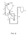
- FIG. 3 shows arrangement that includes a transporter tank after an intermediate pressure tank.
- a stream comprising polymer solids, vaporized and/or liquid diluent, and other components from a slurry polymerization are fed through inlet 60 to an intermediate pressure tank 62.
- the outlet of this tank 62 is equipped with a manual gate 64 that may be closed when one wants to seal the outlet for an out-of-the-ordinary Purpose.
- the manual gate 64 will generally remain open during normal operation, during which an outlet valve 66 regulates the flow of material out of the tank 62.
- the material (polymer solids or a concentrated slurry) passes through valve 66 to the transporter tank 68.
- a vent line 70 is provided between the transporter tank 68 and the intermediate pressure tank to allow easier filling of the transporter tank 68 and to prevent back pressure that would hinder material flow.
- the vent line 70 is equipped with a vent valve 72.
- the vent valve 72 and outlet valve 66 are closed and sealed.
- High pressure gas such as pressurized air is gradually fed to the top of the transporter tank 68, and the material is forced by gas pressure through the transporter outlet 74 to the next processing stage. In this way, the material from the intermediate pressure tank 62 may be transported primarily by a force other than gravity such as by the pressure of the high pressure gas, and it is not necessary to suspend the intermediate pressure tank 68 high above the ground.
- the material from the transporter tank 68 will typically be passed to a receiving tank 76 where the material is separated from the high pressure gas.
- the level of material in the transporter tank 68 may be sensed by a level detector 78.
- the high pressure gas may be provided by an air compressor 80.
- the top of the tank could be designed as a high efficiency cyclone and a metal filter could be used on the top of the cyclone.
- the bottom valve on the transporter tank opens, the material is transported by the flash gas from the high-pressure flash tank at a gange pressure of about 135 psi (930 kPa) to the top of the purge column.
- Polymer transport can take place by dense phase conveying until the line is clear.
- the conveying line could be operated continuously with the transporters valve fully or partially open for coarse adjustment of flow. Fine flow and solids transportation rate adjustment could be achieved by varying the amount of boost gas added to the dense phase conveying line. This gas rate could be controlled by level in the bottom of the transporter.
- a spare cyclone transporter tank would allow for clean out of polymer chunks, should they occur.
- Polymer solids and diluent from the reactor discharge would enter one of the transporter tanks tangentially.
- the polymer solids would fall to the bottom and gas would flow out of the top.
- the flow would be switched to the other transporter tank.
- the valve on the bottom of the first transporter tank is open and dense phase flow of slurry is sent to the top of the purge column.
- the bottom valve is closed.
- the advantages of a system that combines the intermediate pressure tank and the transporter tank include: (1) the flash chamber and purge column structure can be minimized. Plants without high pressure flash tanks can be retrofitted with high pressure flash more economically. (2) Clean out screens could be located at ground level in a location away from the reactor and finishing. (3) The valves for the transporter will probably be much smaller than the valves for the interlock chamber. (4) The smaller valve would not have to frequently cycle open and closed and thus have a much higher steam factor. This is a way to continuously control the flow of solids and gas without a cycling valve in slurry service. (5) Heat may be added to the fluff in the transfer line to the purge column using more flashline heaters.
Claims (16)
- Verfahren für eine Suspensionspolymerisation von Olefinen und für die Trennung von Polymerfeststoffen von Verdünnungsmittel, umfassend
Polymerisieren in einer Reaktionszone von mindestens einem Olefinmonomer in einem flüssigen Verdünnungsmittel zum Erhalten einer flüssigen Verschlämmung, umfassend das flüssige Verdünnungsmittel und Polymerfeststoffe;
Entnehmen eines Teils der Verschlämmung aus der Reaktionszone;
Erhitzen des entnommenen Teils der Verschlämmung;
Weiterleiten des entnommenen Teils der Verschlämmung in eine Mitteldruckzone in welcher eine Mehrheit des Verdünnungsmittels von den Polymerfeststoffen getrennt wird, wobei die Mitteldruckzone unter einem absoluten Druck im Bereich zwischen 100 psi und 1500 psi (690 bis 10300 kPa) steht;
Entnehmen der Polymerfeststoffe aus der Mitteldruckzone;
Überführen der Polymerfeststoffe in eine Reinigungszone, ohne dass sie durch eine Flash-Zone geleitet werde;
Überwachen des Gehalts der Polymerfeststoffe in der Mitteldruckzone; und
Anpassen der Entnahme der Polymerfeststoffe aus der Mitteldruckzone als Reaktion auf den überwachten Gehalt. - Verfahren gemäß Anspruch 1, wobei das abgetrennte Verdünnungsmittel nach der Mitteldruckzone ohne Kompression kondensiert wird.
- Verfahren gemäß Anspruch 1, umfassend Überführen der Polymerfeststoffe von der Mitteldruckzone in eine Transportzone; und Überführen der Polymerfeststoffe von der Transportzone in die Reinigungszone durch eine Kraft, die nicht die Gravitation ist.
- Verfahren gemäß Anspruch 1, umfassend Überführen der Polymerfeststoffe aus der Mitteldruckzone in eine erste Transferzone; und
Überführen der Polymerfeststoffe aus der Mitteldruckzone in eine zweite Transportzone, erreicht der Gehalt der Polymerfeststoffe in der ersten Transferzone eine gewünschte Höhe. - Verfahren gemäß Anspruch 1, wobei die Polymerfeststoffe in die Reinigungszone vorwiegend durch Flash-Gas aus der Mitteldruckzone überführt werden.
- Verfahren gemäß Anspruch 1, wobei die Polymerfeststoffe nach der Mitteldruckzone im Wesentlichen frei von nicht mitgerissenem Verdünnungsmittel sind.
- Verfahren gemäß Anspruch 6, wobei die Polymerfeststoffe nach der Reinigungszone im Wesentlichen frei von mitgerissenem Verdünnungsmittel sind.
- Verfahren gemäß Anspruch 1, umfassend das Erhalten eines ausreichenden Gehalts der Polymerfeststoffe in der Mitteldruckzone, um ein Drucksiegel für die Mitteldruckzone zu bilden.
- Verfahren gemäß Anspruch 6, wobei der Schritt des Steuerns des Grads der Entnahme der Polymerfeststoffe aus der Mitteldruckzone umfasst
Erstellen eines ersten Signals, das den tatsächlichen Gehalt der Polymerfeststoffe in der Mitteldruckzone darstellt;
Erstellen eines zweiten Signals, das den gewünschten Gehalt der Polymerfeststoffe in der Mitteldruckzone darstellt;
Vergleichen des ersten Signals mit dem zweiten Signal und Erstellen eines dritten Signals, das vom Unterschied zwischen dem ersten Signal und dem zweiten Signal abhängt; und
Betätigen des Feststoff-Auslassventils als Reaktion auf das dritte Signal. - Verfahren gemäß Anspruch 1, zudem umfassend das Zurückhalten der Polymerfeststoffe in der Mitteldruckzone während einer Verweilzeit für Polymerfeststoffe, die ausreichend ist, im Wesentlichen das gesamte nicht mitgerissene Verdünnungsmittel zu entfernen.
- Verfahren gemäß Anspruch 10, umfassend Steuern des Grads der Entnahme der Polymerfeststoffe aus der Mitteldruckzone durch Betätigen eines Feststoff-Auslassventils.
- Vorrichtung für die Trennung von Verdünnungsmittel von Polymerfeststoffen, umfassend
eine Mitteldruckkammer, ausgelegt für die Trennung von Verdünnungsmitteldampf von Polymerfeststoffen, wobei die Kammer hat einen Einlass für die Aufnahme einer flüssigen Verschlämmung, umfassend Verdünnungsmittel und Polymerfeststoffe aus einem Polymerverschlämmungsreaktor, einen Feststoffauslass für das Auslassen von Polymerfeststoffen und einen Gasauslass für das Auslassen von verdampftem Verdünnungsmittel, wobei die Mitteldruckkammer fluidisch mit einer Reinigungssäule verbunden ist, ohne dass dazwischen eine Niedrigdruckkammer ist;
einen Gehaltssensor in Verbindung mit der Mitteldruckkammer zum Erkennen des Gehalts an Polymerfeststoffen in der Mitteldruckkammer;
ein Auslassventil, das fluidisch mit dem Gasauslass der Mitteldruckkammer verbunden ist, wobei das Auslassventil als Reaktion auf den erkannten Gehalt betätigt wird;
einen Kondensator, der fluidisch mit dem Gasauslass verbunden ist, für die Aufnahme und Kondensation ohne Kompression des verdampften Verdünnungsmittels; und
wobei die Reinigungssäule fluidisch mit dem Auslassventil verbunden ist, für die Aufnahme der Polymerfeststoffe aus der Mitteldruckkammer. - Trennvorrichtung gemäß Anspruch 12, zudem umfassend
eine Flaumkammer, die dem Auslassventil nachgelagert und fluidisch damit verbunden ist;
ein Flaumkammerventil in fluidischer Verbindung mit der Unterseite der Flaumkammer;
eine Reinigungssäule in fluidischer Verbindung mit dem Flaumkammerventil; und
ein Kontrollsystem, ausgelegt, das Auslassventil und das Flaumkammerventil zu betätigen, so dass die Ventile nicht gleichzeitig geöffnet sind. - Trennvorrichtung gemäß Anspruch 12, umfassend einen ersten Transporttank, der dem Auslassventil nachgelagert und fluidisch damit verbunden ist, wobei der erste Transporttank der Reinigungssäule vorgelagert und fluidisch damit verbunden ist.
- Trennvorrichtung gemäß Anspruch 14, umfassend
einen zweiten Transporttank, der dem Auslassventil nachgelagert und fluidisch damit verbunden ist; und
eine Transporttanksteuerung, die operativ mit dem ersten und dem zweiten Transporttank verbunden ist, wobei die Steuerung ausgelegt ist, den Polymerfluss zwischen dem ersten und dem zweiten Transporttank abzuwechseln. - Trennvorrichtung gemäß Anspruch 12, wobei die Mitteldruckkammer auch ein Transporttank ist.
Applications Claiming Priority (5)
| Application Number | Priority Date | Filing Date | Title |
|---|---|---|---|
| US41125502P | 2002-09-16 | 2002-09-16 | |
| US411255P | 2002-09-16 | ||
| PCT/US2003/029331 WO2004026914A1 (en) | 2002-09-16 | 2003-09-15 | Process and apparatus for separating diluent from polymer solids |
| US10/662,260 US6838531B2 (en) | 2002-09-16 | 2003-09-15 | Process and apparatus for separating diluent from polymer solids |
| US662260 | 2003-09-15 |
Publications (3)
| Publication Number | Publication Date |
|---|---|
| EP1551881A1 EP1551881A1 (de) | 2005-07-13 |
| EP1551881A4 EP1551881A4 (de) | 2007-05-02 |
| EP1551881B1 true EP1551881B1 (de) | 2010-02-10 |
Family
ID=32033536
Family Applications (1)
| Application Number | Title | Priority Date | Filing Date |
|---|---|---|---|
| EP03754705A Revoked EP1551881B1 (de) | 2002-09-16 | 2003-09-15 | Verfahren und vorrichtung zur abtrennung von verdünnungsmittel von polymerfeststoffen |
Country Status (11)
| Country | Link |
|---|---|
| US (2) | US6838531B2 (de) |
| EP (1) | EP1551881B1 (de) |
| AT (1) | ATE457321T1 (de) |
| AU (1) | AU2003272518A1 (de) |
| BR (1) | BR0314384B1 (de) |
| CA (1) | CA2498763C (de) |
| DE (1) | DE60331233D1 (de) |
| DK (1) | DK1551881T3 (de) |
| ES (1) | ES2340993T3 (de) |
| MX (1) | MXPA05002956A (de) |
| WO (1) | WO2004026914A1 (de) |
Families Citing this family (18)
| Publication number | Priority date | Publication date | Assignee | Title |
|---|---|---|---|---|
| US20040136881A1 (en) * | 1997-07-15 | 2004-07-15 | Verser Donald W. | Separation of polymer particles and vaporized diluent in a cyclone |
| EP1586590A1 (de) * | 2004-02-13 | 2005-10-19 | Total Petrochemicals Research Feluy | Stofftransferbehälter zwischen Entspannungsbehälter und Austragskolonne zur Wiedergewinnung von festen Polymeren |
| US7109290B2 (en) * | 2004-06-07 | 2006-09-19 | Chevron Phillips Chemical Company Lp | Polymer transfer within a polymerization system |
| MX2007002216A (es) | 2004-08-27 | 2007-05-04 | Chevron Phillips Chemical Co | Procedimiento de poliolefina eficiente de energia. |
| US7629421B2 (en) * | 2005-12-21 | 2009-12-08 | Chevron Phillips Chemical Company Lp | Monomer recovery by returning column overhead liquid to the reactor |
| US7957947B2 (en) | 2006-08-25 | 2011-06-07 | Chevron Phillips Chemical Company Lp | Method and apparatus for managing volatile organic content in polyolefin |
| EP1918308A1 (de) * | 2006-10-30 | 2008-05-07 | Total Petrochemicals Research Feluy | Verfahren zur Verbesserung der Entgasung von in einem Polymerisationsreaktor hergestellten Polymeraufschlämmungen |
| US7381777B1 (en) | 2007-02-26 | 2008-06-03 | Exxonmobil Chemical Patents Inc. | Method for controlling fouling in slurry-type polymerization reactors |
| US9637570B2 (en) * | 2009-06-11 | 2017-05-02 | Exxonmobil Chemical Patents Inc. | Method and apparatus for reducing fouling |
| WO2011073366A1 (en) * | 2009-12-18 | 2011-06-23 | Total Petrochemicals Research Feluy | Method for monitoring the level of an ethylene polymerization catalyst slurry |
| US9211523B2 (en) | 2010-07-01 | 2015-12-15 | Chevron Phillips Chemical Company Lp | Polyolefin manufacturing system including a membrane fractionation system for diluent recovery |
| TWI520769B (zh) | 2010-09-22 | 2016-02-11 | Jsr Corp | Separating device for solid polymer, separation method of solid polymer, and method for producing rubber material |
| US8440772B2 (en) | 2011-04-28 | 2013-05-14 | Chevron Phillips Chemical Company Lp | Methods for terminating olefin polymerizations |
| US8597582B2 (en) | 2011-06-30 | 2013-12-03 | Chevron Phillips Chemical Company Lp | Flashline heater system and method |
| US10273315B2 (en) | 2012-06-20 | 2019-04-30 | Chevron Phillips Chemical Company Lp | Methods for terminating olefin polymerizations |
| US11512150B2 (en) | 2020-11-17 | 2022-11-29 | Ineos Usa Llc | Polymerization process |
| EP4247862A1 (de) * | 2020-11-17 | 2023-09-27 | Ineos USA LLC | Verfahren |
| US11549748B1 (en) | 2021-10-26 | 2023-01-10 | Chevron Phillips Chemical Company Lp | Emission free fluff transfer system and integrated nitrogen cycle |
Family Cites Families (10)
| Publication number | Priority date | Publication date | Assignee | Title |
|---|---|---|---|---|
| US5376742A (en) * | 1993-09-23 | 1994-12-27 | Quantum Chemical Corporation | Monomer recovery in gas phase fluid bed olefin polymerization |
| US5624877A (en) * | 1994-02-25 | 1997-04-29 | Phillips Petroleum Company | Process for producing polyolefins |
| US5455314A (en) * | 1994-07-27 | 1995-10-03 | Phillips Petroleum Company | Method for controlling removal of polymerization reaction effluent |
| CN1166444C (zh) * | 1998-03-20 | 2004-09-15 | 埃克森美孚化学专利公司 | 浆液聚合中的挥发性物质的连续除去 |
| US6045661A (en) * | 1998-05-20 | 2000-04-04 | Phillips Petroleum Company | Process and apparatus for recovering diluent, monomer, and comonomer from a polymerization reactor effluent |
| US6262191B1 (en) * | 1999-03-09 | 2001-07-17 | Phillips Petroleum Company | Diluent slip stream to give catalyst wetting agent |
| US6559247B2 (en) * | 1999-03-09 | 2003-05-06 | Chevron Phillips Chemical Company, Lp | Direct recycle fractionation method using a swing column |
| US6420497B1 (en) * | 1999-12-03 | 2002-07-16 | Phillips Petroleum Company | Solids concentration in slurry polymerization |
| CN101125291B (zh) * | 2001-09-26 | 2010-10-13 | 伊内奥斯美国公司 | 一体化的化工工艺控制 |
| ATE380200T1 (de) * | 2002-10-30 | 2007-12-15 | Borealis Tech Oy | Verfahren und vorrichtung zur herstellung von olefinpolymeren |
-
2003
- 2003-09-15 BR BRPI0314384-8A patent/BR0314384B1/pt active IP Right Grant
- 2003-09-15 ES ES03754705T patent/ES2340993T3/es not_active Expired - Lifetime
- 2003-09-15 DK DK03754705.6T patent/DK1551881T3/da active
- 2003-09-15 AU AU2003272518A patent/AU2003272518A1/en not_active Abandoned
- 2003-09-15 MX MXPA05002956A patent/MXPA05002956A/es active IP Right Grant
- 2003-09-15 US US10/662,260 patent/US6838531B2/en not_active Expired - Lifetime
- 2003-09-15 DE DE60331233T patent/DE60331233D1/de not_active Expired - Lifetime
- 2003-09-15 CA CA002498763A patent/CA2498763C/en not_active Expired - Lifetime
- 2003-09-15 WO PCT/US2003/029331 patent/WO2004026914A1/en not_active Application Discontinuation
- 2003-09-15 AT AT03754705T patent/ATE457321T1/de not_active IP Right Cessation
- 2003-09-15 EP EP03754705A patent/EP1551881B1/de not_active Revoked
-
2004
- 2004-09-23 US US10/948,015 patent/US6953553B2/en not_active Expired - Lifetime
Also Published As
| Publication number | Publication date |
|---|---|
| AU2003272518A1 (en) | 2004-04-08 |
| ES2340993T3 (es) | 2010-06-14 |
| US20050034968A1 (en) | 2005-02-17 |
| WO2004026914A1 (en) | 2004-04-01 |
| US6838531B2 (en) | 2005-01-04 |
| CA2498763C (en) | 2009-11-10 |
| BR0314384A (pt) | 2005-07-26 |
| US6953553B2 (en) | 2005-10-11 |
| ATE457321T1 (de) | 2010-02-15 |
| DE60331233D1 (de) | 2010-03-25 |
| DK1551881T3 (da) | 2010-05-25 |
| MXPA05002956A (es) | 2005-10-19 |
| CA2498763A1 (en) | 2004-04-01 |
| US20040116597A1 (en) | 2004-06-17 |
| EP1551881A1 (de) | 2005-07-13 |
| EP1551881A4 (de) | 2007-05-02 |
| BR0314384B1 (pt) | 2014-10-21 |
Similar Documents
| Publication | Publication Date | Title |
|---|---|---|
| EP1551881B1 (de) | Verfahren und vorrichtung zur abtrennung von verdünnungsmittel von polymerfeststoffen | |
| US5183866A (en) | Polymer recovery process | |
| AU755016B2 (en) | Continuous slurry polymerization volatile removal | |
| US6319997B1 (en) | Continuous slurry polymerization volatile removal | |
| US6858682B2 (en) | Continuous slurry polymerization volatile removal | |
| EP1689794B1 (de) | Trennung von polymerteilchen und verdampftem verdünnungsmittel in einem zyklon | |
| US7524904B2 (en) | Process and apparatus for separating polymer solids, hydrocarbon fluids, and purge gas | |
| JP2005517768A (ja) | ループ反応炉を用いる連続スラリー重合化処理 | |
| EP3965924A1 (de) | System und verfahren zur schnellen erwärmung eines dumptanks | |
| RU2673556C1 (ru) | Способ получения высушенного порошка | |
| WO2003039739A1 (en) | Continuous removal of polymerization slurry | |
| AU2002300690B2 (en) | Continuous slurry polymerization volatile removal | |
| CN100384885C (zh) | 用于将稀释剂与聚合物固体分离的方法及设备 | |
| MXPA00011306A (en) | Continuous slurry polymerization volatile removal |
Legal Events
| Date | Code | Title | Description |
|---|---|---|---|
| PUAI | Public reference made under article 153(3) epc to a published international application that has entered the european phase |
Free format text: ORIGINAL CODE: 0009012 |
|
| 17P | Request for examination filed |
Effective date: 20050418 |
|
| AK | Designated contracting states |
Kind code of ref document: A1 Designated state(s): AT BE BG CH CY CZ DE DK EE ES FI FR GB GR HU IE IT LI LU MC NL PT RO SE SI SK TR |
|
| AX | Request for extension of the european patent |
Extension state: AL LT LV MK |
|
| DAX | Request for extension of the european patent (deleted) | ||
| RIN1 | Information on inventor provided before grant (corrected) |
Inventor name: TAIT, JOHN, H. Inventor name: REID, THOMAS, A. Inventor name: BURNS, DAVID, H. Inventor name: VERSER, DONALD, W. Inventor name: KUFELD, SCOTT, E. |
|
| A4 | Supplementary search report drawn up and despatched |
Effective date: 20070330 |
|
| RIC1 | Information provided on ipc code assigned before grant |
Ipc: C08F 2/14 20060101AFI20040408BHEP Ipc: C08F 6/24 20060101ALI20070326BHEP Ipc: C08F 6/00 20060101ALI20070326BHEP |
|
| 17Q | First examination report despatched |
Effective date: 20070814 |
|
| GRAP | Despatch of communication of intention to grant a patent |
Free format text: ORIGINAL CODE: EPIDOSNIGR1 |
|
| GRAS | Grant fee paid |
Free format text: ORIGINAL CODE: EPIDOSNIGR3 |
|
| GRAA | (expected) grant |
Free format text: ORIGINAL CODE: 0009210 |
|
| AK | Designated contracting states |
Kind code of ref document: B1 Designated state(s): AT BE BG CH CY CZ DE DK EE ES FI FR GB GR HU IE IT LI LU MC NL PT RO SE SI SK TR |
|
| REG | Reference to a national code |
Ref country code: GB Ref legal event code: FG4D |
|
| REG | Reference to a national code |
Ref country code: CH Ref legal event code: EP |
|
| REG | Reference to a national code |
Ref country code: IE Ref legal event code: FG4D |
|
| REF | Corresponds to: |
Ref document number: 60331233 Country of ref document: DE Date of ref document: 20100325 Kind code of ref document: P |
|
| REG | Reference to a national code |
Ref country code: NL Ref legal event code: T3 |
|
| REG | Reference to a national code |
Ref country code: DK Ref legal event code: T3 |
|
| REG | Reference to a national code |
Ref country code: ES Ref legal event code: FG2A Ref document number: 2340993 Country of ref document: ES Kind code of ref document: T3 |
|
| PG25 | Lapsed in a contracting state [announced via postgrant information from national office to epo] |
Ref country code: PT Free format text: LAPSE BECAUSE OF FAILURE TO SUBMIT A TRANSLATION OF THE DESCRIPTION OR TO PAY THE FEE WITHIN THE PRESCRIBED TIME-LIMIT Effective date: 20100611 |
|
| PG25 | Lapsed in a contracting state [announced via postgrant information from national office to epo] |
Ref country code: AT Free format text: LAPSE BECAUSE OF FAILURE TO SUBMIT A TRANSLATION OF THE DESCRIPTION OR TO PAY THE FEE WITHIN THE PRESCRIBED TIME-LIMIT Effective date: 20100210 Ref country code: SI Free format text: LAPSE BECAUSE OF FAILURE TO SUBMIT A TRANSLATION OF THE DESCRIPTION OR TO PAY THE FEE WITHIN THE PRESCRIBED TIME-LIMIT Effective date: 20100210 Ref country code: FI Free format text: LAPSE BECAUSE OF FAILURE TO SUBMIT A TRANSLATION OF THE DESCRIPTION OR TO PAY THE FEE WITHIN THE PRESCRIBED TIME-LIMIT Effective date: 20100210 |
|
| PG25 | Lapsed in a contracting state [announced via postgrant information from national office to epo] |
Ref country code: GR Free format text: LAPSE BECAUSE OF FAILURE TO SUBMIT A TRANSLATION OF THE DESCRIPTION OR TO PAY THE FEE WITHIN THE PRESCRIBED TIME-LIMIT Effective date: 20100511 Ref country code: SE Free format text: LAPSE BECAUSE OF FAILURE TO SUBMIT A TRANSLATION OF THE DESCRIPTION OR TO PAY THE FEE WITHIN THE PRESCRIBED TIME-LIMIT Effective date: 20100210 Ref country code: CY Free format text: LAPSE BECAUSE OF FAILURE TO SUBMIT A TRANSLATION OF THE DESCRIPTION OR TO PAY THE FEE WITHIN THE PRESCRIBED TIME-LIMIT Effective date: 20100210 Ref country code: RO Free format text: LAPSE BECAUSE OF FAILURE TO SUBMIT A TRANSLATION OF THE DESCRIPTION OR TO PAY THE FEE WITHIN THE PRESCRIBED TIME-LIMIT Effective date: 20100210 Ref country code: EE Free format text: LAPSE BECAUSE OF FAILURE TO SUBMIT A TRANSLATION OF THE DESCRIPTION OR TO PAY THE FEE WITHIN THE PRESCRIBED TIME-LIMIT Effective date: 20100210 |
|
| PLBI | Opposition filed |
Free format text: ORIGINAL CODE: 0009260 |
|
| PG25 | Lapsed in a contracting state [announced via postgrant information from national office to epo] |
Ref country code: BG Free format text: LAPSE BECAUSE OF FAILURE TO SUBMIT A TRANSLATION OF THE DESCRIPTION OR TO PAY THE FEE WITHIN THE PRESCRIBED TIME-LIMIT Effective date: 20100510 Ref country code: CZ Free format text: LAPSE BECAUSE OF FAILURE TO SUBMIT A TRANSLATION OF THE DESCRIPTION OR TO PAY THE FEE WITHIN THE PRESCRIBED TIME-LIMIT Effective date: 20100210 Ref country code: SK Free format text: LAPSE BECAUSE OF FAILURE TO SUBMIT A TRANSLATION OF THE DESCRIPTION OR TO PAY THE FEE WITHIN THE PRESCRIBED TIME-LIMIT Effective date: 20100210 |
|
| PLAX | Notice of opposition and request to file observation + time limit sent |
Free format text: ORIGINAL CODE: EPIDOSNOBS2 |
|
| 26 | Opposition filed |
Opponent name: TOTAL PETROCHEMICALS RESEARCH FELUY Effective date: 20101110 Opponent name: INEOS EUROPE LIMITED Effective date: 20101110 |
|
| PLAF | Information modified related to communication of a notice of opposition and request to file observations + time limit |
Free format text: ORIGINAL CODE: EPIDOSCOBS2 |
|
| PG25 | Lapsed in a contracting state [announced via postgrant information from national office to epo] |
Ref country code: MC Free format text: LAPSE BECAUSE OF NON-PAYMENT OF DUE FEES Effective date: 20100930 |
|
| REG | Reference to a national code |
Ref country code: CH Ref legal event code: PL |
|
| PLBB | Reply of patent proprietor to notice(s) of opposition received |
Free format text: ORIGINAL CODE: EPIDOSNOBS3 |
|
| REG | Reference to a national code |
Ref country code: DE Ref legal event code: R119 Ref document number: 60331233 Country of ref document: DE Effective date: 20110401 |
|
| PG25 | Lapsed in a contracting state [announced via postgrant information from national office to epo] |
Ref country code: CH Free format text: LAPSE BECAUSE OF NON-PAYMENT OF DUE FEES Effective date: 20100930 Ref country code: IE Free format text: LAPSE BECAUSE OF NON-PAYMENT OF DUE FEES Effective date: 20100915 Ref country code: DE Free format text: LAPSE BECAUSE OF NON-PAYMENT OF DUE FEES Effective date: 20110401 Ref country code: LI Free format text: LAPSE BECAUSE OF NON-PAYMENT OF DUE FEES Effective date: 20100930 |
|
| PLAB | Opposition data, opponent's data or that of the opponent's representative modified |
Free format text: ORIGINAL CODE: 0009299OPPO |
|
| R26 | Opposition filed (corrected) |
Opponent name: INEOS COMMERCIAL SERVICES UK LIMITED Effective date: 20101110 Opponent name: TOTAL PETROCHEMICALS RESEARCH FELUY Effective date: 20101110 |
|
| PG25 | Lapsed in a contracting state [announced via postgrant information from national office to epo] |
Ref country code: HU Free format text: LAPSE BECAUSE OF FAILURE TO SUBMIT A TRANSLATION OF THE DESCRIPTION OR TO PAY THE FEE WITHIN THE PRESCRIBED TIME-LIMIT Effective date: 20100811 Ref country code: LU Free format text: LAPSE BECAUSE OF NON-PAYMENT OF DUE FEES Effective date: 20100915 |
|
| PG25 | Lapsed in a contracting state [announced via postgrant information from national office to epo] |
Ref country code: TR Free format text: LAPSE BECAUSE OF FAILURE TO SUBMIT A TRANSLATION OF THE DESCRIPTION OR TO PAY THE FEE WITHIN THE PRESCRIBED TIME-LIMIT Effective date: 20100210 |
|
| RDAF | Communication despatched that patent is revoked |
Free format text: ORIGINAL CODE: EPIDOSNREV1 |
|
| APAH | Appeal reference modified |
Free format text: ORIGINAL CODE: EPIDOSCREFNO |
|
| APBM | Appeal reference recorded |
Free format text: ORIGINAL CODE: EPIDOSNREFNO |
|
| APBP | Date of receipt of notice of appeal recorded |
Free format text: ORIGINAL CODE: EPIDOSNNOA2O |
|
| PLAB | Opposition data, opponent's data or that of the opponent's representative modified |
Free format text: ORIGINAL CODE: 0009299OPPO |
|
| APBQ | Date of receipt of statement of grounds of appeal recorded |
Free format text: ORIGINAL CODE: EPIDOSNNOA3O |
|
| R26 | Opposition filed (corrected) |
Opponent name: TOTAL RESEARCH & TECHNOLOGY FELUY Effective date: 20101110 |
|
| PLAB | Opposition data, opponent's data or that of the opponent's representative modified |
Free format text: ORIGINAL CODE: 0009299OPPO |
|
| R26 | Opposition filed (corrected) |
Opponent name: INEOS SALES (UK) LIMITED Effective date: 20101110 |
|
| REG | Reference to a national code |
Ref country code: FR Ref legal event code: PLFP Year of fee payment: 14 |
|
| PGFP | Annual fee paid to national office [announced via postgrant information from national office to epo] |
Ref country code: DK Payment date: 20160927 Year of fee payment: 14 Ref country code: GB Payment date: 20160927 Year of fee payment: 14 Ref country code: NL Payment date: 20160926 Year of fee payment: 14 |
|
| PGFP | Annual fee paid to national office [announced via postgrant information from national office to epo] |
Ref country code: FR Payment date: 20160926 Year of fee payment: 14 |
|
| PGFP | Annual fee paid to national office [announced via postgrant information from national office to epo] |
Ref country code: ES Payment date: 20160926 Year of fee payment: 14 |
|
| PGFP | Annual fee paid to national office [announced via postgrant information from national office to epo] |
Ref country code: IT Payment date: 20160923 Year of fee payment: 14 |
|
| REG | Reference to a national code |
Ref country code: DE Ref legal event code: R064 Ref document number: 60331233 Country of ref document: DE Ref country code: DE Ref legal event code: R103 Ref document number: 60331233 Country of ref document: DE |
|
| APBU | Appeal procedure closed |
Free format text: ORIGINAL CODE: EPIDOSNNOA9O |
|
| RDAG | Patent revoked |
Free format text: ORIGINAL CODE: 0009271 |
|
| STAA | Information on the status of an ep patent application or granted ep patent |
Free format text: STATUS: PATENT REVOKED |
|
| 27W | Patent revoked |
Effective date: 20170315 |
|
| GBPR | Gb: patent revoked under art. 102 of the ep convention designating the uk as contracting state |
Effective date: 20170315 |
|
| PGFP | Annual fee paid to national office [announced via postgrant information from national office to epo] |
Ref country code: BE Payment date: 20170927 Year of fee payment: 15 |