EP1551017A2 - Optische Abtastvorrichtung fähig sphärische Aberration zu korrigieren - Google Patents
Optische Abtastvorrichtung fähig sphärische Aberration zu korrigieren Download PDFInfo
- Publication number
- EP1551017A2 EP1551017A2 EP05000176A EP05000176A EP1551017A2 EP 1551017 A2 EP1551017 A2 EP 1551017A2 EP 05000176 A EP05000176 A EP 05000176A EP 05000176 A EP05000176 A EP 05000176A EP 1551017 A2 EP1551017 A2 EP 1551017A2
- Authority
- EP
- European Patent Office
- Prior art keywords
- mirror
- piezoelectric element
- circular
- light
- thickness
- Prior art date
- Legal status (The legal status is an assumption and is not a legal conclusion. Google has not performed a legal analysis and makes no representation as to the accuracy of the status listed.)
- Withdrawn
Links
Images


Classifications
-
- G—PHYSICS
- G11—INFORMATION STORAGE
- G11B—INFORMATION STORAGE BASED ON RELATIVE MOVEMENT BETWEEN RECORD CARRIER AND TRANSDUCER
- G11B7/00—Recording or reproducing by optical means, e.g. recording using a thermal beam of optical radiation by modifying optical properties or the physical structure, reproducing using an optical beam at lower power by sensing optical properties; Record carriers therefor
- G11B7/12—Heads, e.g. forming of the optical beam spot or modulation of the optical beam
- G11B7/135—Means for guiding the beam from the source to the record carrier or from the record carrier to the detector
- G11B7/1362—Mirrors
-
- G—PHYSICS
- G11—INFORMATION STORAGE
- G11B—INFORMATION STORAGE BASED ON RELATIVE MOVEMENT BETWEEN RECORD CARRIER AND TRANSDUCER
- G11B7/00—Recording or reproducing by optical means, e.g. recording using a thermal beam of optical radiation by modifying optical properties or the physical structure, reproducing using an optical beam at lower power by sensing optical properties; Record carriers therefor
- G11B7/12—Heads, e.g. forming of the optical beam spot or modulation of the optical beam
- G11B7/135—Means for guiding the beam from the source to the record carrier or from the record carrier to the detector
- G11B7/1392—Means for controlling the beam wavefront, e.g. for correction of aberration
- G11B7/13925—Means for controlling the beam wavefront, e.g. for correction of aberration active, e.g. controlled by electrical or mechanical means
- G11B7/13927—Means for controlling the beam wavefront, e.g. for correction of aberration active, e.g. controlled by electrical or mechanical means during transducing, e.g. to correct for variation of the spherical aberration due to disc tilt or irregularities in the cover layer thickness
-
- G—PHYSICS
- G11—INFORMATION STORAGE
- G11B—INFORMATION STORAGE BASED ON RELATIVE MOVEMENT BETWEEN RECORD CARRIER AND TRANSDUCER
- G11B7/00—Recording or reproducing by optical means, e.g. recording using a thermal beam of optical radiation by modifying optical properties or the physical structure, reproducing using an optical beam at lower power by sensing optical properties; Record carriers therefor
- G11B2007/0003—Recording, reproducing or erasing systems characterised by the structure or type of the carrier
- G11B2007/0009—Recording, reproducing or erasing systems characterised by the structure or type of the carrier for carriers having data stored in three dimensions, e.g. volume storage
- G11B2007/0013—Recording, reproducing or erasing systems characterised by the structure or type of the carrier for carriers having data stored in three dimensions, e.g. volume storage for carriers having multiple discrete layers
Definitions
- the present invention relates generally to optical pickup devices and particularly to optical pickup devices having a function correcting spherical aberration.
- Compact disks CDs
- DVD digital versatile disks
- apparatuses including an optical pickup device to optically read the information from the optical disks.
- a source of light emits a laser beam of light which is in turn reflected by a mirror and gathered by an objective lens to illuminate an optical disk's recording surface on a desired track.
- the track reflects and thus returns the light which is in turn detected by a photodetector to read the track's information.
- the light gathered by the objective lens can provide spherical aberration.
- Spherical aberration means that, of rays focused by the objective lens, a ray passing through a portion of the lens remote from the optical axis, or the lens's peripheral portion, and a ray passing close to the optical axis, or the lens's center, are focused at different locations.
- an optical disk cannot have its information satisfactorily reproduced.
- the objective lens is designed to correct spherical aberration for a thickness of an optical disk predetermined. If the optical disk is not uniform in thickness, however, and an amount of correction does not match, spherical aberration is introduced. Furthermore, if the optical disk has a recording layer formed of multiple layers, and a jump is made to a different layer, an amount of correction does not match, and spherical aberration is introduced.
- Such spherical aberration is prevented for example by a method employing a liquid crystal device to modulate a phase corresponding to the spherical aberration, as disclosed in Japanese Patent Laying-Open No. 2003-141771.
- the present invention contemplates an optical pickup device that can have a simplified structure to reduce spherical aberration.
- the present invention in one aspect provides an optical pickup device allowing a laser beam of light emitted from a source of a laser beam of light to be reflected by a mirror to provide a reflection of light which is in turn focused by an objective lens on an optical storage medium
- the optical pickup device including: a circular mirror reflecting the laser beam of light; and a mirror actuator including a piezoelectric element having a thickness in a direction perpendicular to a surface of the mirror, and a circular surface bonded to a circular rear surface of the mirror such that the center of the circular surface of the piezoelectric element and that of the circular rear surface of the mirror match, the piezoelectric element receiving a potential to cause the circular surface bonded to the mirror to expand/contract radially around 360 degrees by a uniform ratio to allow the mirror to have a surface modified in geometry, the piezoelectric element being adjusted in thickness so that as the piezoelectric element expands/contracts, the piezoelectric element allows the mirror to have a surface with a ratio of
- the present invention in another aspect provides an optical pickup device allowing a laser beam of light emitted from a source of a laser beam of light to be reflected by a mirror to provide a reflection of light in turn focused by an objective lens on an optical storage medium
- the optical pickup device including: a circular mirror reflecting the laser beam of light; and a mirror actuator including a piezoelectric element having a thickness in a direction perpendicular to a surface of the mirror, and a circular surface bonded to a circular rear surface of the mirror such that the center of the circular surface of the piezoelectric element and that of the circular rear surface of the mirror match, the piezoelectric element receiving a potential to cause the circular surface bonded to the mirror to expand/contract radially around 360 degrees by a uniform ratio to allow the mirror to have a surface modified in geometry, the piezoelectric element varying in thickness in a predetermined number of steps to be thicker toward the center and thinner toward the perimeter to have regions different in thickness each forming with an adjacent region a boundary in the form an
- the present invention in still another aspect provides an optical pickup device allowing a laser beam of light emitted from a source of a laser beam of light to be reflected by a mirror to provide a reflection of light which is in turn focused by an objective lens on an optical storage medium
- the optical pickup device including: a circular mirror having a thickness reflecting the laser beam of light; and a mirror actuator including a piezoelectric element having a circular surface bonded to a circular rear surface of the mirror such that the center of the circular surface of the piezoelectric element and that of the circular rear surface of the mirror match, the piezoelectric element receiving a potential to cause the circular surface bonded to the mirror to expand/contract radially around 360 degrees by a uniform ratio to allow the mirror to have a surface modified in geometry, the mirror varying in thickness in a predetermined number of steps to be thicker toward the center and thinner toward the perimeter to have regions different in thickness each forming with an adjacent region a boundary in the form an ellipse having longer and shorter axes in radial and
- the present invention in still another aspect provides an optical pickup device allowing a laser beam of light emitted from a source of a laser beam of light to be reflected by a mirror to provide a reflection of light in turn focused by an objective lens on an optical storage medium
- the optical pickup device including: a circular mirror reflecting the laser beam of light; and a mirror actuator including a piezoelectric element having a uniform thickness in a direction perpendicular to a surface of the mirror, and an elliptical surface having longer and shorter axes in radial and tangential directions, respectively, and bonded to a circular rear surface of the mirror such that the center of the elliptical surface of the piezoelectric element and that of the circular rear surface of the mirror match, the piezoelectric element receiving a potential to cause the elliptical surface to expand/contract radially around 360 degrees by a uniform ratio to allow the mirror to have a surface modified in geometry.
- the present optical pickup device can have a simplified structure to reduce spherical aberration.
- the present embodiment relates to an optical pickup device including a mirror actuator having a piezoelectric element with anisotropic thickness to provide a minimized amount of spherical aberration.
- Fig. 1 shows a main portion of an optical system of the pickup device.
- the optical pickup device includes a source of light 1, a collimator 2, a polarizing beam splitter 3, a circular, turning/aberration correction mirror 4, an objective lens 5, a cylindrical lens 7, a photodetector 8, and a mirror actuator 10.
- the source of light 1 emits a beam 13.
- Collimator 2 collimates beam 13 into a collimated beam of light 11.
- Mirror 4 turns the collimated beam of light 11 in a direction, i.e., reflects beam 11 toward an optical disk 6 to provide a reflection of light 12.
- Objective lens 5 allows the reflection of light 12 to illuminate optical disk 6 on an information recording surface.
- the information recording surface has a bit train, which modulates the reflection of light in optical intensity.
- the reflection of light thus modulated then passes through objective lens 5 and is reflected by mirror 4 and then polarizing beam splitter 3 and converged by cylindrical lens 7 and thus input to photodetector 8.
- Photodetector 8 receives the light, which is used to reproduce information of optical disk 6 and control objective lens 5 to focus and track appropriately.
- a control circuit (not shown) separates the light incident on photodetector 8 into light of a center portion and that of a peripheral portion and detects their respective focus positions to detect an amount of spherical aberration.
- the control circuit is driven by the detected amount of spherical aberration to control mirror actuator 10, which supports mirror 4, to modify the mirror 4 mirror surface in geometry to reduce the amount of spherical aberration.
- Fig. 2A shows an optical path of the reflection of light 12 provided when mirror 4 has a mirror surface with a typical or flat geometry. As shown in the figure, spherical aberration has been introduced.
- Fig. 2B shows an optical path of the reflection of light 12 provided when mirror 4 has its mirror surface modified in geometry. As shown in the figure, the mirror surface is modified in geometry to reduce an amount of spherical aberration.
- Fig. 3 shows a structure of mirror actuator 10.
- mirror actuator 10 includes a piezoelectric element 21, a branch 22 supporting piezoelectric element 21, and a fixture 23.
- Piezoelectric element 21 is bonded on a rear surface of mirror 4.
- the surface of piezoelectric element 21 that is bonded to the rear surface of mirror 4 is a circle, and the circle's center matches that of the rear, circular surface of the mirror.
- Piezoelectric element 21 has its thickness in a direction perpendicular to the mirror surface.
- piezoelectric element 21 When piezoelectric element 21 has potential applied thereon, piezoelectric element 21 expands/contracts. More specifically, when piezoelectric element 21 receives positive potential, piezoelectric element 21 has the circular surface bonded to mirror 4 expanding radially around 360 degrees by a uniform ratio, as indicated in Fig. 3 by an arrow (1). As mirror 4 is bonded to piezoelectric element 21, mirror 4 flexes to concave, and the reflection of light 12 is thus converged.
- piezoelectric element 21 when piezoelectric element 21 receives negative potential, then as indicated in Fig. 3 by an arrow (2), piezoelectric element 21 has the circular surface bonded to mirror 4 contracting radially around 360 degrees by a uniform ratio. As mirror 4 is bonded to piezoelectric element 21, mirror 4 flexes to protrude, and the reflection of light 12 is thus diverged.
- mirror 4 has a mirror surface receiving the collimated beam of light 11 in an elliptical spot.
- a mirror angle refers to an angle of the collimated beam of light 11 incident on the mirror 4 mirror surface having a typical geometry.
- a tangential direction is a direction parallel to the mirror surface of mirror 4 in normal condition and connecting locations on the mirror that receive rays of light closest to and remotest from the optical disk 6 surface.
- a radial direction is a direction parallel to the mirror surface of mirror 4 in normal condition and perpendicular to the tangential direction.
- flexing mirror 4 in the tangential and radial directions by equal amounts i.e., providing a curvature uniform in the tangential and radial directions
- Fig. 5 represents a relationship between a radius of curvature and an amount of spherical aberration.
- the figure indicates an uncorrected amount of spherical aberration, radii of curvature in the tangential and radial directions, respectively, as modified for correction, and a corrected amount of spherical aberration for a mirror angle of 45° for each thickness of material for an optical disk.
- a minimized amount of spherical aberration is provided when the radius of curvature in the tangential direction is set to be twice that of curvature in the radial direction.
- Figs. 6A-6C mirror 4 is flexed to set a radius of curvature a in the tangential direction to be twice a radius of curvature b in the radial direction.
- Fig. 6A generally shows a geometry of a mirror surface of mirror 4 and Figs. 6B and 6B show the same mirror surface's geometry in the tangential and radial directions, respectively.
- Flexing mirror 4 requires changing in geometry piezoelectric element 21 bonded to the rear surface of mirror 4.
- piezoelectric element 21 expands and contracts radially by a uniform ratio by an mount, as controlled by a single value in potential, and its amount of expansion and contraction cannot be adjusted in the tangential and radial directions separately.
- piezoelectric element 21 is designed to have thickness in the tangential and radial directions in appropriate amounts, respectively, to allow mirror 4 to have a radius of curvature in the tangential direction twice that of curvature in the radial direction. More specifically, the fact is utilized that when piezoelectric element 21 smaller in thickness expands/contracts, mirror 4 more readily flexes.
- a thickness of piezoelectric element 21 and an amount of flexure of mirror 4 have a relationship depending for example on material for piezoelectric element 21. Accordingly, the piezoelectric element 21 thickness in the tangential and radial directions is designed for each individual piezoelectric element used.
- mirror 4 has a radius of curvature in the tangential direction that is twice that of curvature in the radial direction to provide a minimized amount of spherical aberration.
- a description will be provided for a mirror angle other than 45°.
- Fig. 7 indicates for each mirror angle a ratio of a radius of curvature in the radial direction relative to that of curvature in the tangential direction that provides a minimized amount of spherical aberration. If the figure's relationship is represented in an expression then for a mirror angle ⁇ a ratio of a radius of curvature in the radial direction relative to that of curvature in the tangential direction will be (cos (2 ⁇ ) + 1)/2, and such a ratio can be achieved simply by designing piezoelectric element 21 in thickness in the tangential and radial directions so as to correspond to each individual piezoelectric element used.
- the present embodiment provides an optical pickup device including piezoelectric element 12 adjusted in thickness in both tangential and radial directions to allow a turning/aberration correction mirror angled by ⁇ to have a ratio of a radius of curvature in the radial direction to that of curvature in the tangential direction set to be (cos (20) + 1)/2. A minimized amount of spherical aberration can thus be achieved.
- the present embodiment relates to an optical pickup device including a mirror actuator having a piezoelectric element with anisotropic thickness to provide an amount of spherical aberration smaller than conventional.
- the first embodiment contemplates a minimized amount of spherical aberration. This requires complicated adjustment of a piezoelectric element in thickness to allow turning/aberration correction mirror 12 to have radii of curvature in tangential and radial directions in an optimal ratio, as shown in Fig. 7.
- the present embodiment contemplates providing a simple method to achieve an amount of spherical aberration smaller than conventional.
- the present embodiment provides an optical pickup device distinguished from the first embodiment's optical pickup device shown in Fig. 1 by mirror actuator 80 that is structured and operates, as will be described hereinafter.
- Fig. 8 shows a structure of mirror actuator 80 in the present embodiment.
- mirror actuator 80 includes a piezoelectric element 81, a branch 22 supporting piezoelectric element 81, and a fixture 23.
- Piezoelectric element 81 is bonded on a rear surface of mirror 4.
- the surface of piezoelectric element 81 that is bonded to the rear surface of mirror 4 is a circle, and the circle's center matches that of the rear, circular surface of the mirror.
- Piezoelectric element 81 has its thickness in a direction perpendicular to the mirror surface.
- piezoelectric element 81 When piezoelectric element 81 has potential applied thereon, piezoelectric element 81 expands/contracts. More specifically, when piezoelectric element 81 receives positive potential, piezoelectric element 81 has the circular surface bonded to mirror 4 expanding radially around 360 degrees by a uniform ratio, as indicated in Fig. 8 by an arrow (1). As mirror 4 is bonded to piezoelectric element 81, mirror 4 flexes to concave, and the reflection of light 12 is thus converged.
- piezoelectric element 81 when piezoelectric element 81 receives negative potential, then as indicated in Fig. 8 by an arrow (2), piezoelectric element 81 has the circular surface bonded to mirror 4 contracting radially around 360 degrees by a uniform ratio. As mirror 4 is bonded to piezoelectric element 81, mirror 4 flexes to protrude, and the reflection of light 12 is thus diverged.
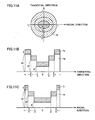
- Piezoelectric element 81 becomes smaller in thickness toward the center by varying in three steps, as shown in Fig. 8. More specifically, if the piezoelectric element 81 has a center portion or an area A having a thickness d1, an intermediate portion or an area B having a thickness d2, and a peripheral portion or an area C having a thickness d3, then d1 ⁇ d2 ⁇ d3 is established.
- an area of a thickness and another, adjacent area of a different thickness form a boundary which, as seen in a plane perpendicular to the mirror's centerline, is in the form an ellipse having longer and shorter axes in the radial and tangential directions, respectively.
- the mirror's centerline indicates a straight line perpendicular to the mirror surface of mirror 4 in normal condition and passing the center of the mirror surface.
- the center portion or area A and the intermediate portion or area B form a boundary in the form of an ellipse having longer and shorter axes in the radial and tangential directions, respectively, as seen in a plane perpendicular to the mirror's centerline, and so do the intermediate area B and the peripheral area C.
- Fig. 9A shows areas A-C as seen in a direction perpendicular to the mirror surface.
- Fig. 9B and 9C illustrate how in the tangential and radial directions, respectively, piezoelectric element 81 varies in thickness.
- piezoelectric element 81 at a thin portion has a ratio larger in the radial direction than the tangential direction.
- turning/aberration correction mirror 4 more readily flexes in the radial direction, and its mirror surface can be deformed to have a radius of curvature in the tangential direction larger than that of curvature in the radial direction.
- a smaller amount of spherical aberration can be achieved than when radii of curvature in the tangential and radial directions are equal.
- the present embodiment provides an optical pickup device that includes piezoelectric element 81 having a thin portion with a ratio larger in the radial direction than the tangential direction to allow turning/aberration correction mirror 4 to have a mirror surface having a geometry with a radius of curvature in the tangential direction larger than that of curvature in the radial direction.
- a smaller amount of spherical aberration can be achieved that when radii of curvature in the tangential and radial directions are equal.
- the present embodiment relates to an optical pickup device including a mirror having anisotropic thickness to provide an amount of spherical aberration smaller than conventional.
- turning/aberration correction mirror 4 is uniform in thickness and piezoelectric element 81 varies in thickness.
- a piezoelectric element 71 is uniform in thickness, whereas a turning/aberration correction mirror 74 varies in thickness, similarly as has been described in the second embodiment for piezoelectric element 81.
- the present embodiment provides an optical pickup device distinguished from the first embodiment's optical pickup device shown in Fig. 1 by mirror actuator 70 and turning/aberration correction mirror 74 that are structured and operate, as will be described hereinafter.
- Fig. 10 shows a structure of mirror actuator 70 and mirror 74 in the present embodiment.
- mirror actuator 70 includes a piezoelectric element 71, branch 22 supporting piezoelectric element 71, and fixture 23.
- Piezoelectric element 71 is bonded on a rear surface of mirror 74.
- the surface of piezoelectric element 71 that is bonded to the rear surface of mirror 74 is a circle, and the circle's center matches that of the rear, circular surface of the mirror.
- Piezoelectric element 71 has a uniform thickness in a direction perpendicular to the mirror surface.
- piezoelectric element 71 When piezoelectric element 71 has potential applied thereon, piezoelectric element 71 expands/contracts. More specifically, when piezoelectric element 71 receives positive potential, piezoelectric element 71 has the circular surface bonded to mirror 74 expanding radially around 360 degrees by a uniform ratio, as indicated in Fig. 10 by an arrow (1). As mirror 74 is bonded to piezoelectric element 71, mirror 74 flexes to concave, and the reflection of light 12 is thus converged.
- piezoelectric element 71 when piezoelectric element 71 receives negative potential, then as indicated in Fig. 10 by an arrow (2), piezoelectric element 71 has the circular surface bonded to mirror 74 contracting radially around 360 degrees by a uniform ratio. As mirror 74 is bonded to piezoelectric element 71, mirror 74 flexes to protrude, and the reflection of light 12 is thus diverged.
- Mirror 74 becomes smaller in thickness toward the center by varying in three steps, as shown in Fig. 10. More specifically, if the piezoelectric element 71 has a center portion or an area A having a thickness d1, an intermediate portion or an area B having a thickness d2, and a peripheral portion or an area C having a thickness d3, then d 1 ⁇ d2 ⁇ d3 is established.
- an area of a thickness and another, adjacent area of a different thickness form a boundary which, as seen in a plane perpendicular to the mirror's centerline, is in the form an ellipse having longer and shorter axes in the radial and tangential directions, respectively.
- the center portion or area A and the intermediate portion or area B form a boundary in the form of an ellipse having longer and shorter axes in the radial and tangential directions, respectively, as seen in a plane perpendicular to the mirror's centerline, and so do the intermediate area B and the peripheral area C.
- Fig. 11A shows areas A-C as seen in a direction perpendicular to the mirror surface.
- Fig. 11B and 11C illustrate how in the tangential and radial directions, respectively, mirror 74 varies in thickness.
- mirror 74 at a thin portion has a ratio larger in the radial direction than the tangential direction. As such, mirror 74 more readily flexes in the radial direction, and its mirror surface can be deformed to have a radius of curvature in the tangential direction larger than that of curvature in the radial direction. A smaller amount of spherical aberration can be achieved than when radii of curvature in the tangential and radial directions are equal.
- the present embodiment provides an optical pickup device that includes turning/aberration correction mirror 74 having a thin portion with a ratio larger in the radial direction than the tangential direction to allow mirror 74 to have a mirror surface having a geometry with a radius of curvature in the tangential direction larger than that of curvature in the radial direction.
- a smaller amount of spherical aberration can be achieved that when radii of curvature in the tangential and radial directions are equal.
- the present embodiment relates to an optical pickup device including a mirror actuator having a piezoelectric element uniform in thickness and elliptical as seen in cross section.
- the present embodiment provides an optical pickup device distinguished from the first embodiment's optical pickup device shown in Fig. 1 by a mirror actuator 60 that is structured and operates, as will be described hereinafter.
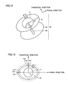
- Fig. 12 shows a structure of mirror actuator 60 and mirror 4 in the present embodiment.
- mirror actuator 60 includes a piezoelectric element 61, branch 22 supporting piezoelectric element 71, and a fixture 63.
- Piezoelectric element 61 is bonded on a rear surface of mirror 4.
- the surface of piezoelectric element 61 that is bonded to mirror 74 is an ellipse, and the ellipse's center matches that of the rear, circular surface of the mirror. It should be noted, however, that the elliptical surface of piezoelectric element 61 is larger than the circular surface of mirror 4.
- Piezoelectric element 61 has a uniform thickness in a direction perpendicular to the mirror surface.
- piezoelectric element 61 When piezoelectric element 61 has potential applied thereon, piezoelectric element 61 expands/contracts. More specifically, when piezoelectric element 61 receives positive potential, piezoelectric element 61 has the elliptical surface expanding radially around 360 degrees by a uniform ratio, as indicated in Fig. 12 by an arrow (1). As mirror 4 is bonded to piezoelectric element 61, mirror 4 flexes to concave, and the reflection of light 12 is thus converged.
- piezoelectric element 61 when piezoelectric element 61 receives negative potential, then as indicated in Fig. 12 by an arrow (2), piezoelectric element 61 has the elliptical surface contracting radially around 360 degrees by a uniform ratio. As mirror 4 is bonded to piezoelectric element 61, mirror 74 flexes to protrude, and the reflection of light 12 is thus diverged.
- Fig. 13 illustrates piezoelectric element 61 and mirror 4 as seen in a direction perpendicular to the mirror surface.
- mirror 4 is in the form of a circle whereas piezoelectric element 61 is in the form of an ellipse longer in the radial direction.
- Piezoelectric element 61 in normal condition has a longer radius r rad and a shorter radius r tan .
- piezoelectric element 61 expands in the tangential direction by an amount lt of (k1 - 1) ⁇ r tan and in the radial direction by an amount lr of (k1 - 1) x r rad .
- lr > lt piezoelectric element 61 expands to be larger in the radial direction than the tangential direction so that mirror 4 can flex greater in the radial direction, i.e., have a radius of curvature in the tangential direction larger than that of curvature in the radial direction.
- a smaller amount of spherical aberration can be provided than when radii of curvature in the tangential and radial directions are equal.
- the piezoelectric element contracts in the tangential direction by amount lt of ( 1 - k2) ⁇ r tan and in the radial direction by amount lr of ( 1 - k2) ⁇ r rad .
- piezoelectric element 61 contracts to be smaller in the radial direction than the tangential direction so that mirror 4 can flex greater in the radial direction, i.e., have a radius of curvature in the tangential direction larger than that of curvature in the radial direction.
- a smaller amount of spherical aberration can be provided than when radii of curvature in the tangential and radial directions are equal.
- the present embodiment provides an optical pickup device including piezoelectric element 61 having an elliptical geometry with longer and shorter axes extending in radial and tangential directions, respectively, to allow turning/aberration correction mirror 4 to have a mirror surface deformed to have a radius of curvature in the tangential direction larger than that of curvature in the radial direction to provide an amount of spherical aberration smaller than when radii of curvature in the tangential and radial directions are equal.
- the present invention is not limited to the above described embodiments and also for example includes a variation described hereinafter.
- the present invention in the second and third embodiments provides a piezoelectric element varying in thickness in three steps, however the present invention is not limited thereto and the piezoelectric element may vary in thickness in four or more steps or gradually.
Landscapes
- Physics & Mathematics (AREA)
- Optics & Photonics (AREA)
- Optical Head (AREA)
- Mechanical Light Control Or Optical Switches (AREA)
Applications Claiming Priority (2)
| Application Number | Priority Date | Filing Date | Title |
|---|---|---|---|
| JP2004000554 | 2004-01-05 | ||
| JP2004000554A JP3867706B2 (ja) | 2004-01-05 | 2004-01-05 | 光ピックアップ装置 |
Publications (2)
| Publication Number | Publication Date |
|---|---|
| EP1551017A2 true EP1551017A2 (de) | 2005-07-06 |
| EP1551017A3 EP1551017A3 (de) | 2008-01-23 |
Family
ID=34567576
Family Applications (1)
| Application Number | Title | Priority Date | Filing Date |
|---|---|---|---|
| EP05000176A Withdrawn EP1551017A3 (de) | 2004-01-05 | 2005-01-05 | Optische Abtastvorrichtung fähig sphärische Aberration zu korrigieren |
Country Status (4)
| Country | Link |
|---|---|
| US (1) | US7283434B2 (de) |
| EP (1) | EP1551017A3 (de) |
| JP (1) | JP3867706B2 (de) |
| CN (1) | CN1306499C (de) |
Cited By (2)
| Publication number | Priority date | Publication date | Assignee | Title |
|---|---|---|---|---|
| EP1768118A3 (de) * | 2005-08-22 | 2008-01-23 | Funai Electric Co., Ltd. | Optische Lesekopfvorrichtung |
| EP1914742A2 (de) | 2006-10-16 | 2008-04-23 | Funai Electric Co., Ltd. | Verfahren zur Konfiguration der Form eines form-deformierbaren Spiegels, optische Aufnahmevorrichtung, und Aufnahme- und Wiedergabevorrichtung |
Families Citing this family (2)
| Publication number | Priority date | Publication date | Assignee | Title |
|---|---|---|---|---|
| JP2007172786A (ja) * | 2005-12-26 | 2007-07-05 | Pentax Corp | 光情報処理装置 |
| CN113820850B (zh) * | 2021-08-23 | 2023-08-11 | 中国科学院光电技术研究所 | 一种集成球面反射镜的mems微快门阵列器件 |
Family Cites Families (9)
| Publication number | Priority date | Publication date | Assignee | Title |
|---|---|---|---|---|
| FR2462758A1 (fr) * | 1979-08-03 | 1981-02-13 | Thomson Csf | Dispositif optique d'acces a une piste portee par un support d'information et systeme de memoire optique comportant un tel dispositif |
| US4761774A (en) * | 1985-05-30 | 1988-08-02 | Matsushita Electric Industrial Co., Ltd. | Optical disc drive apparatus |
| ES2101409T3 (es) * | 1994-08-24 | 1997-07-01 | Schablonentechnik Kufstein Ag | Dispositivo para fabricar una plantilla para impresion. |
| JPH11110768A (ja) * | 1997-09-30 | 1999-04-23 | Sony Corp | 光ピックアップ装置 |
| TW442783B (en) * | 1999-07-09 | 2001-06-23 | Ind Tech Res Inst | Folding mirror |
| US6496453B2 (en) * | 2000-03-27 | 2002-12-17 | Matsushita Electric Industrial Co., Ltd. | Optical pickup |
| JP3904893B2 (ja) | 2001-11-06 | 2007-04-11 | シャープ株式会社 | 光ピックアップ装置 |
| JP2003185816A (ja) * | 2001-12-14 | 2003-07-03 | Ricoh Co Ltd | 形状可変鏡及び光ディスク情報入出力装置 |
| JP2003338071A (ja) * | 2002-05-21 | 2003-11-28 | Olympus Optical Co Ltd | 光ピックアップ装置 |
-
2004
- 2004-01-05 JP JP2004000554A patent/JP3867706B2/ja not_active Expired - Fee Related
- 2004-12-30 US US11/026,490 patent/US7283434B2/en not_active Expired - Fee Related
-
2005
- 2005-01-05 CN CNB2005100064998A patent/CN1306499C/zh not_active Expired - Fee Related
- 2005-01-05 EP EP05000176A patent/EP1551017A3/de not_active Withdrawn
Cited By (3)
| Publication number | Priority date | Publication date | Assignee | Title |
|---|---|---|---|---|
| EP1768118A3 (de) * | 2005-08-22 | 2008-01-23 | Funai Electric Co., Ltd. | Optische Lesekopfvorrichtung |
| EP1914742A2 (de) | 2006-10-16 | 2008-04-23 | Funai Electric Co., Ltd. | Verfahren zur Konfiguration der Form eines form-deformierbaren Spiegels, optische Aufnahmevorrichtung, und Aufnahme- und Wiedergabevorrichtung |
| EP1914742A3 (de) * | 2006-10-16 | 2008-09-10 | Funai Electric Co., Ltd. | Verfahren zur Konfiguration der Form eines form-deformierbaren Spiegels, optische Aufnahmevorrichtung, und Aufnahme- und Wiedergabevorrichtung |
Also Published As
| Publication number | Publication date |
|---|---|
| US7283434B2 (en) | 2007-10-16 |
| JP3867706B2 (ja) | 2007-01-10 |
| JP2005196841A (ja) | 2005-07-21 |
| CN1306499C (zh) | 2007-03-21 |
| EP1551017A3 (de) | 2008-01-23 |
| US20050152237A1 (en) | 2005-07-14 |
| CN1637887A (zh) | 2005-07-13 |
Similar Documents
| Publication | Publication Date | Title |
|---|---|---|
| JP3640059B2 (ja) | 収差補正装置及びこれを用いた光学装置 | |
| CN101359489B (zh) | 物镜、光学拾取装置和光盘设备 | |
| JP2006073076A (ja) | 光記録媒体用対物光学系およびこれを用いた光ピックアップ装置 | |
| JP2001209966A (ja) | 光ピックアップ | |
| JPH1064103A (ja) | 光ピックアップ装置 | |
| US7283434B2 (en) | Optical pickup device capable of correcting spherical aberration | |
| US7230905B2 (en) | Optical pickup using two-wavelength light source module and method for correcting position difference | |
| US6739730B2 (en) | Optical pickup deformable mirror | |
| JP2004511059A (ja) | 光走査デバイス | |
| US20050063285A1 (en) | Optical disc drive and optical pickup | |
| WO2007119410A1 (ja) | 光学ヘッドおよび光ディスク装置 | |
| US20050146998A1 (en) | Optical pickup device capable of correcting spherical aberration | |
| KR100486818B1 (ko) | 다른구조를갖는광기록매체에기록및/또는이로부터판독하기위한장치 | |
| US20060087928A1 (en) | Mirror element and mirror array | |
| US7184385B2 (en) | Optical scanning device | |
| KR100403927B1 (ko) | 광 픽업 | |
| JP4059340B2 (ja) | 波面収差補正装置および光ピックアップ | |
| EP1684279B1 (de) | Optische Lesekopfvorrichtung | |
| JP2004171682A (ja) | 光学情報記録再生装置 | |
| JPH10334472A (ja) | 光ピックアップ | |
| US7447136B2 (en) | Optical pickup and optical disc apparatus | |
| JP2006092602A (ja) | 光ピックアップ装置 | |
| JP2004310939A (ja) | 収差検出装置、基材厚検出装置、光ヘッドおよび光情報処理装置、コンピュータ、映像記録装置、映像再生装置、カーナビゲーションシステム | |
| JP2005063572A (ja) | 光ピックアップおよび光ディスク再生装置 | |
| JP2000076691A (ja) | 光学ヘッド |
Legal Events
| Date | Code | Title | Description |
|---|---|---|---|
| PUAI | Public reference made under article 153(3) epc to a published international application that has entered the european phase |
Free format text: ORIGINAL CODE: 0009012 |
|
| AK | Designated contracting states |
Kind code of ref document: A2 Designated state(s): AT BE BG CH CY CZ DE DK EE ES FI FR GB GR HU IE IS IT LI LT LU MC NL PL PT RO SE SI SK TR |
|
| AX | Request for extension of the european patent |
Extension state: AL BA HR LV MK YU |
|
| PUAL | Search report despatched |
Free format text: ORIGINAL CODE: 0009013 |
|
| AK | Designated contracting states |
Kind code of ref document: A3 Designated state(s): AT BE BG CH CY CZ DE DK EE ES FI FR GB GR HU IE IS IT LI LT LU MC NL PL PT RO SE SI SK TR |
|
| AX | Request for extension of the european patent |
Extension state: AL BA HR LV MK YU |
|
| AKX | Designation fees paid | ||
| STAA | Information on the status of an ep patent application or granted ep patent |
Free format text: STATUS: THE APPLICATION IS DEEMED TO BE WITHDRAWN |
|
| 18D | Application deemed to be withdrawn |
Effective date: 20080724 |
|
| REG | Reference to a national code |
Ref country code: DE Ref legal event code: 8566 |