EP1550934A1 - Multi-stage NCO - Google Patents
Multi-stage NCO Download PDFInfo
- Publication number
- EP1550934A1 EP1550934A1 EP04030702A EP04030702A EP1550934A1 EP 1550934 A1 EP1550934 A1 EP 1550934A1 EP 04030702 A EP04030702 A EP 04030702A EP 04030702 A EP04030702 A EP 04030702A EP 1550934 A1 EP1550934 A1 EP 1550934A1
- Authority
- EP
- European Patent Office
- Prior art keywords
- remainder
- input
- accumulator
- quotient
- output
- Prior art date
- Legal status (The legal status is an assumption and is not a legal conclusion. Google has not performed a legal analysis and makes no representation as to the accuracy of the status listed.)
- Withdrawn
Links
Images


Classifications
-
- G—PHYSICS
- G06—COMPUTING; CALCULATING OR COUNTING
- G06F—ELECTRIC DIGITAL DATA PROCESSING
- G06F1/00—Details not covered by groups G06F3/00 - G06F13/00 and G06F21/00
- G06F1/02—Digital function generators
- G06F1/03—Digital function generators working, at least partly, by table look-up
- G06F1/0321—Waveform generators, i.e. devices for generating periodical functions of time, e.g. direct digital synthesizers
- G06F1/0328—Waveform generators, i.e. devices for generating periodical functions of time, e.g. direct digital synthesizers in which the phase increment is adjustable, e.g. by using an adder-accumulator
Definitions
- the invention relates generally to automatic test equipment, and more particularly high accuracy digital counter circuits.
- Numerical counter oscillators are convenient multi-bit registers that increment a summed value in response to a periodic input signal, such as a digital clock waveform.
- One application for an NCO is in a technique known as direct-digital-synthesis, often used to generate a variable frequency clock.
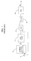
- Direct-digital-synthesis (DDS) for generating variable frequency clocks are well-known in the art and, as shown in Figure 1, generally involve driving the input of an NCO 10 with a digital clock signal 12. The counter incrementally advances with each subsequent clock period.
- Each multi-bit count value is mapped to a sine value look-up table or memory 14 for a digital representation of an analog sine wave phase angle.
- the digital representation is then fed through a digital-to-analog converter (DAC) 16 where the accumulating phase angle results in a complete sinusoidal analog waveform.
- DAC digital-to-analog converter
- Further conditioning of the analog signal by a filter 18 and a phase-locked-loop (PLL) 20 often occurs to form the desired clock.
- the frequency of the desired end waveform typically relies on the accuracy of the NCO.
- the "A” and “B” terms together represent a ratio of Fref to F NCO .
- the "B” term traditionally represents a binary divisor dependent on the number of output bits N in the NCO.
- the ratio A/B forces a 1/2 N resolution when programming a desired clock frequency F NCO .
- the resulting problem is that a user desiring to program a variable frequency clock to, for example, one gigahertz, because of the limited number of available values for "B", might have to accept a frequency of 1.001 gigahertz. In some applications, such as automatic test equipment, this level of inaccuracy is problematic.
- NCO that provides a high level of accuracy that correspondingly allows more flexibility in frequency resolution for variable frequency clock generators and other circuits that utilize NCOs.
- the NCO described herein satisfies these needs.
- the numeric counter oscillator described herein provides a unique way to achieve high accuracy and repeatability for circuits that use direct-digital-synthesis techniques.
- the numeric counter oscillator in one form comprises a numeric counter oscillator comprising a quotient accumulator and a remainder accumulator.
- the quotient accumulator has a programmable input for receiving a QUOTIENT value, a reference clock input and a multi-bit output. The output is adapted for transmitting an output value OUT representing an accumulated quotient sum.
- the multi-bit output increments by a predetermined amount in response to each reference clock period.
- the remainder accumulator comprises programmable inputs for receiving respective REMAINDER and DIVISOR values, a a reference clock input and a multi-bit output representing an accumulated digital remainder sum less than a predefined digital integer.
- the remainder accumulator further comprises a comparator having a first input for receiving a programmed divisor value, and a second input for receiving the remainder accumulator multi-bit output.
- the comparator is operative to generate an increment carry signal for application to the quotient accumulator when the remainder multi-bit output reaches the predefined integer value.
- the numeric counter oscillator (NCO) described herein provides a way to maximize the accuracy of an oscillator output with respect to a desired frequency ratio between two clock frequencies. This enables a flexible choice of resolution in the NCO output for use with a variable frequency clock, or timestamp as more fully described below.
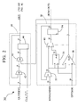
- the multi-stage numerical counter oscillator generally designated 30, comprises a quotient accumulator 40 and a remainder accumulator 50.
- the remainder accumulator complements the quotient accumulator to allow for flexible clock frequency resolution programming.
- the quotient accumulator includes a first adder 42 that receives at one input an eighteen-bit quotient value QUOTIENT, and an eightee-bit input fed back from the accumulator output OUT.
- the first adder feeds a second adder 44 with the result of the summed QUOTIENT and OUT values.
- the second adder sums the QUOTIENT/OUT with a carry input from the remainder accumulator 50.
- the output from the second adder is shifted into a multi-bit register 46 clocked by input clock CLK. The output of the register OUT may then be used as the accumulator input.
- the remainder accumulator 50 includes a third adder 52 that receives a thirty-bit remainder input REMAINDER, along with an increment value from a second multi-bit register 54.
- the output of the third adder is fed as an input to a subtractor 56 and a comparator 58.
- a thirty-bit divisor value DIVISOR provides a second input for the subtractor and comparator.
- a multiplexer 60 includes a control input coupled to the comparator output to selectively pass the subtractor output or the third adder output to the second register 54.
- Figure 3 illustrates a cycle-by-cycle example of how the multi-stage NCO operates.
- This example assumes a desired ratio between the desired frequency FNCO and the reference frequency FREF of 10/3. This assumption results in a programmed quotient of three (3), a remainder of one (1), and a divisor of three (3).
- the remainder accumulator has an incremental value of zero, with the quotient accumulator output incremented by three (3).
- cycle 1 the remainder accumulator increments by one (1), resulting in an adder output of two (2).
- the quotient accumulator increments by three (3) again, for an output value, at the adder , of six (6).
- the adder input is incremented to generate a value of three (3) at the input to the subtractor and the comparator. Since both inputs to the comparator are equal, a carry signal is generated and fed to the quotient accumulator (the second adder input). The carry value is added with the incrementing three (3) on the fourth clock pulse. As a result, the output OUT exhibits a ten (10).
- the entire carry-generation process repeats every three (3) cycles (the DIVISOR value) to produce an accurate counter output OUT.
- the resolution of the clock is programmable to a very fine resolution, for example, to one hertz.
- the QUOTIENT, REMAINDER, and DIVISOR input values are entirely programmable by a user in establishing the desired frequency ratio.
- the NCO 30 in one application may be conveniently employed in a variable frequency clock generator, generally designated 100, utilizing direct-digital-synthesis techniques well-known to those skilled in the art, and briefly described earlier herein.
- the NCO feeds its high-accuracy output to a look-up sine table 102 having amplitude values for phase input. Each accumulated amplitude value is then fed to a digital-to-analog converter (DAC) 104 where a stepped analog waveform results.
- DAC digital-to-analog converter
- the waveform is then smoothed and processed by a filter 106 and clipped by a clipper 107 to make a clock.
- a phase-locked-loop 108 further filters the waveform for optimum fidelity.
- the NCO 30 may be employed as a standard circuit block to generate timestamp data. Timestamps are often useful for establishing relative timings between signal occurances or events. For this application, both of the accumulator outputs are used such that the quotient accumulator output represents integers of a specified unit of time, such as nanoseconds.
Abstract
Description
- The invention relates generally to automatic test equipment, and more particularly high accuracy digital counter circuits.
- Numerical counter oscillators (NCO), or accumulators, are convenient multi-bit registers that increment a summed value in response to a periodic input signal, such as a digital clock waveform. One application for an NCO is in a technique known as direct-digital-synthesis, often used to generate a variable frequency clock. Direct-digital-synthesis (DDS) for generating variable frequency clocks are well-known in the art and, as shown in Figure 1, generally involve driving the input of an NCO 10 with a
digital clock signal 12. The counter incrementally advances with each subsequent clock period. - Each multi-bit count value is mapped to a sine value look-up table or
memory 14 for a digital representation of an analog sine wave phase angle. The digital representation is then fed through a digital-to-analog converter (DAC) 16 where the accumulating phase angle results in a complete sinusoidal analog waveform. Further conditioning of the analog signal by afilter 18 and a phase-locked-loop (PLL) 20 often occurs to form the desired clock. - Conventionally, the frequency of the desired end waveform typically relies on the accuracy of the NCO. The degree of accuracy is typically characterized by the equation FNCO = Fref(A/B), where FNCO is the desired frequency and Fref is the digital input clock frequency. The "A" and "B" terms together represent a ratio of Fref to FNCO . The "B" term traditionally represents a binary divisor dependent on the number of output bits N in the NCO.
- In other words, the ratio A/B forces a 1/2N resolution when programming a desired clock frequency FNCO. The resulting problem is that a user desiring to program a variable frequency clock to, for example, one gigahertz, because of the limited number of available values for "B", might have to accept a frequency of 1.001 gigahertz. In some applications, such as automatic test equipment, this level of inaccuracy is problematic.
- What is needed and currently unavailable is an NCO that provides a high level of accuracy that correspondingly allows more flexibility in frequency resolution for variable frequency clock generators and other circuits that utilize NCOs. The NCO described herein satisfies these needs.
- The numeric counter oscillator described herein provides a unique way to achieve high accuracy and repeatability for circuits that use direct-digital-synthesis techniques.
- To realize the foregoing advantages, the numeric counter oscillator in one form comprises a numeric counter oscillator comprising a quotient accumulator and a remainder accumulator. The quotient accumulator has a programmable input for receiving a QUOTIENT value, a reference clock input and a multi-bit output. The output is adapted for transmitting an output value OUT representing an accumulated quotient sum. The multi-bit output increments by a predetermined amount in response to each reference clock period. The remainder accumulator comprises programmable inputs for receiving respective REMAINDER and DIVISOR values, a a reference clock input and a multi-bit output representing an accumulated digital remainder sum less than a predefined digital integer. The remainder accumulator further comprises a comparator having a first input for receiving a programmed divisor value, and a second input for receiving the remainder accumulator multi-bit output. The comparator is operative to generate an increment carry signal for application to the quotient accumulator when the remainder multi-bit output reaches the predefined integer value.
- Other features and advantages of the present invention will be apparent from the following detailed description when read in conjunction with the accompanying drawings.
- The invention will be better understood by reference to the following more detailed description and accompanying drawings in which
- FIG. 1 is a high-level block diagram of a conventional circuit for generating a variable frequency clock;
- FIG. 2 is a block diagram of an improved numerical counter oscillator;
- FIG. 3 is a table showing various values at different points in the improved NCO of Figure 2 for each clock cycle; and
- FIG. 4 is a high-level block diagram of a variable frequency clock generator employing the improved numeric counter oscillator of Figure 2.
-
- The numeric counter oscillator (NCO) described herein provides a way to maximize the accuracy of an oscillator output with respect to a desired frequency ratio between two clock frequencies. This enables a flexible choice of resolution in the NCO output for use with a variable frequency clock, or timestamp as more fully described below.
- Referring now to Figure 2, the multi-stage numerical counter oscillator, generally designated 30, comprises a
quotient accumulator 40 and aremainder accumulator 50. The remainder accumulator complements the quotient accumulator to allow for flexible clock frequency resolution programming. - Further referring to Figure 2, the quotient accumulator includes a
first adder 42 that receives at one input an eighteen-bit quotient value QUOTIENT, and an eightee-bit input fed back from the accumulator output OUT. The first adder feeds asecond adder 44 with the result of the summed QUOTIENT and OUT values. The second adder sums the QUOTIENT/OUT with a carry input from theremainder accumulator 50. The output from the second adder is shifted into amulti-bit register 46 clocked by input clock CLK. The output of the register OUT may then be used as the accumulator input. - With continued reference to Figure 2, the
remainder accumulator 50 includes athird adder 52 that receives a thirty-bit remainder input REMAINDER, along with an increment value from a secondmulti-bit register 54. The output of the third adder is fed as an input to asubtractor 56 and acomparator 58. A thirty-bit divisor value DIVISOR provides a second input for the subtractor and comparator. Amultiplexer 60 includes a control input coupled to the comparator output to selectively pass the subtractor output or the third adder output to thesecond register 54. - Figure 3 illustrates a cycle-by-cycle example of how the multi-stage NCO operates. This example assumes a desired ratio between the desired frequency FNCO and the reference frequency FREF of 10/3. This assumption results in a programmed quotient of three (3), a remainder of one (1), and a divisor of three (3).
- With the assumptions above as one example, at cycle zero (0), the remainder accumulator has an incremental value of zero, with the quotient accumulator output incremented by three (3). With
cycle 1, the remainder accumulator increments by one (1), resulting in an adder output of two (2). The quotient accumulator increments by three (3) again, for an output value, at the adder , of six (6). - With continued reference to Figure 3, at cycle 2 (the third clock pulse), the adder input is incremented to generate a value of three (3) at the input to the subtractor and the comparator. Since both inputs to the comparator are equal, a carry signal is generated and fed to the quotient accumulator (the second adder input). The carry value is added with the incrementing three (3) on the fourth clock pulse. As a result, the output OUT exhibits a ten (10).
- The entire carry-generation process repeats every three (3) cycles (the DIVISOR value) to produce an accurate counter output OUT. As a result, the resolution of the clock is programmable to a very fine resolution, for example, to one hertz. Of course, the QUOTIENT, REMAINDER, and DIVISOR input values are entirely programmable by a user in establishing the desired frequency ratio.
- With reference now to Figure 4, the NCO 30 in one application may be conveniently employed in a variable frequency clock generator, generally designated 100, utilizing direct-digital-synthesis techniques well-known to those skilled in the art, and briefly described earlier herein. The NCO feeds its high-accuracy output to a look-up sine table 102 having amplitude values for phase input. Each accumulated amplitude value is then fed to a digital-to-analog converter (DAC) 104 where a stepped analog waveform results. The waveform is then smoothed and processed by a
filter 106 and clipped by aclipper 107 to make a clock. Preferably, a phase-locked-loop 108 further filters the waveform for optimum fidelity. - In another application, and referring back to Figure 2, the
NCO 30 may be employed as a standard circuit block to generate timestamp data. Timestamps are often useful for establishing relative timings between signal occurances or events. For this application, both of the accumulator outputs are used such that the quotient accumulator output represents integers of a specified unit of time, such as nanoseconds. - Those skilled in the art will recognize the many benefits and advantages afforded by the present invention. Of significant importance is the dual accumulator aspect of the NCO, which enables the quotient to be regularly corrected during operation. This allows for a high degree of resolution flexibility for applications such as variable frequency waveform generation and timestamping.
- While the invention has been particularly shown and described with reference to the preferred embodiments thereof, it will be understood by those skilled in the art that various changes in form and detail may be made therein without departing from the spirit and scope of the invention.
Claims (7)
- A numeric counter oscillator comprising:a quotient accumulator, the quotient accumulator having a programmable input for receiving a QUOTIENT value, a reference clock input and a multi-bit output, the output adapted for transmitting an output vaule OUT representing an accumulated quotient sum, the multi-bit output incrementing by a predetermined amount in response to each reference clock period;a remainder accumulator, the remainder accumulator having programmable inputs for receiving respective REMAINDER and DIVISOR values, a a reference clock input and a multi-bit output representing an accumulated digital remainder sum less than a predefined digital integer, the remainder accumulator further comprising a comparator having a first input for receiving a programmed divisor value, and a second input for receiving the remainder accumulator multi-bit output, the comparator operative to generate an increment carry signal for application to the quotient accumulator when the remainder multi-bit output reaches the predefined integer value.
- A numeric counter oscillator according to claim 1 wherein the quotient accumulator comprises:a shift register having a clock input for receiving the input reference clock signal;a first summing stage for receiving the quotient input, and comprising a second input coupled to the accumulator output; anda second summing stage disposed in series with the first stage and having an input coupled to the comparator output to receive the carry increment signal, the second summing stage further comprising an output coupled to the input of the shift register.
- A numeric counter oscillator according to claim 1 wherein the remainder accumulator comprises:a third summing stage having an input for receiving the REMAINDER value;a subtractor with a pair of inputs for receiving,m respectively, the summed output from the third summing stage and the DIVISOR value; anda second shift register for incrementing the remainder accumulator output in response to the input clock, and feeding back the output to the third summing stage.
- A numeric counter oscillator for providing a numerical solution to the relationship A/B, where B comprises a DIVISOR, and the decimal solution comprises a QUOTIENT + REMAINDER, the numerical counter oscillator comprising:means for accumulating a quotient sum in response to an input QUOTIENT value; andmeans for generating a remainder sum in response to a REMAINDER input value and a DIVISOR input value, the means for generating a remainder sum comprising means for generating a carry signal to increment the quotient sum when the remainder sum equates to the DIVISOR input value.
- A numeric counter oscillator according to claim 4 wherein the means for accumulating a quotient sum comprises:a quotient accumulator, the quotient accumulator having a programmable input for receiving a QUOTIENT value, a reference clock input and a multi-bit output, the output adapted for transmitting an output vaule OUT representing an accumulated quotient sum, the multi-bit output incrementing by a predetermined amount in response to each reference clock period.
- A numeric counter oscillator according to claim 4 wherein the means for accumulating a remainder sum comprises:a remainder accumulator, the remainder accumulator having programmable inputs for receiving respective REMAINDER and DIVISOR values, a a reference clock input and a multi-bit output representing an accumulated digital remainder sum less than a predefined digital integer, the remainder accumulator further comprising a comparator having a first input for receiving a programmed divisor value, and a second input for receiving the remainder accumulator multi-bit output, the comparator operative to generate an increment carry signal for application to the quotient accumulator when the remainder multi-bit output reaches the predefined integer value.
- A method of generating a desired numeric counter oscillator frequency based on a reference frequency, the desired frequency and reference frequency having the relationship A/B, where B comprises a DIVISOR, and the decimal solution comprises a QUOTIENT + REMAINDER, the method including the steps:generating a reference clock having the reference frequency and period;incrementing a first accumulator for each reference waveform period, the first accumulator having a QUOTIENT input and an output for keeping track of an accumulated sum;incrementing a second counter by each reference waveform period, the second counter having a divisor input DIVISOR related to the QUOTIENT input for keeping track of a remainder sum; andcomparing the remainder sum to the DIVISOR input, and when the remainder sum reaches the DIVISOR value, generating a carry increment for accumulation in the first counter.
Applications Claiming Priority (2)
| Application Number | Priority Date | Filing Date | Title |
|---|---|---|---|
| US748488 | 1996-11-08 | ||
| US10/748,488 US7064616B2 (en) | 2003-12-29 | 2003-12-29 | Multi-stage numeric counter oscillator |
Publications (1)
| Publication Number | Publication Date |
|---|---|
| EP1550934A1 true EP1550934A1 (en) | 2005-07-06 |
Family
ID=34574768
Family Applications (1)
| Application Number | Title | Priority Date | Filing Date |
|---|---|---|---|
| EP04030702A Withdrawn EP1550934A1 (en) | 2003-12-29 | 2004-12-23 | Multi-stage NCO |
Country Status (5)
| Country | Link |
|---|---|
| US (1) | US7064616B2 (en) |
| EP (1) | EP1550934A1 (en) |
| JP (1) | JP2005198296A (en) |
| SG (1) | SG113005A1 (en) |
| TW (1) | TWI258921B (en) |
Cited By (2)
| Publication number | Priority date | Publication date | Assignee | Title |
|---|---|---|---|---|
| WO2006004829A2 (en) * | 2004-06-30 | 2006-01-12 | Teradyne, Inc. | Precise time measurement apparatus and method |
| EP1819076A1 (en) * | 2006-02-14 | 2007-08-15 | Harris Corporation | Controlling an accumulation of timing errors in a synchronous system |
Families Citing this family (21)
| Publication number | Priority date | Publication date | Assignee | Title |
|---|---|---|---|---|
| JP2004193996A (en) * | 2002-12-11 | 2004-07-08 | Samsung Electronics Co Ltd | Numerically controlled oscillator, digital frequency converter and radio equipment |
| WO2005079534A2 (en) * | 2004-02-19 | 2005-09-01 | Georgia Tech Research Corporation | Systems and methods for parallel communication |
| US7454681B2 (en) * | 2004-11-22 | 2008-11-18 | Teradyne, Inc. | Automatic test system with synchronized instruments |
| US7319936B2 (en) * | 2004-11-22 | 2008-01-15 | Teradyne, Inc. | Instrument with interface for synchronization in automatic test equipment |
| KR100663938B1 (en) | 2005-11-16 | 2007-01-02 | 엠텍비젼 주식회사 | Numerical controlled oscillator and method for correcting the same |
| TW200736509A (en) * | 2006-03-21 | 2007-10-01 | King Motor Technology Co Ltd | A position-locating method for servomotor controller |
| US7953782B2 (en) * | 2007-05-18 | 2011-05-31 | Ess Technology, Inc. | Digital forced oscillation by direct digital synthesis |
| TWI397264B (en) * | 2008-05-15 | 2013-05-21 | Realtek Semiconductor Corp | Fractional-n phase-locked-loop and method |
| US9083578B1 (en) * | 2013-07-08 | 2015-07-14 | Maxim Integrated Products, Inc. | Numerically controlled oscillator with fractional frequency control word inputs |
| CN103795345B (en) * | 2014-02-13 | 2016-08-17 | 深圳市汇顶科技股份有限公司 | Sinusoidal wave generating means and method |
| US9397670B2 (en) | 2014-07-02 | 2016-07-19 | Teradyne, Inc. | Edge generator-based phase locked loop reference clock generator for automated test system |
| US9797936B2 (en) * | 2015-03-05 | 2017-10-24 | National Instruments Corporation | Counter enhancements for improved performance and ease-of-use |
| US10139449B2 (en) | 2016-01-26 | 2018-11-27 | Teradyne, Inc. | Automatic test system with focused test hardware |
| US11095295B2 (en) | 2018-06-26 | 2021-08-17 | Silicon Laboratories Inc. | Spur cancellation for spur measurement |
| CN110764439B (en) * | 2018-07-25 | 2022-09-06 | 上海英威腾工业技术有限公司 | Servo drive pulse output frequency divider and use method thereof |
| US10680622B2 (en) * | 2018-09-27 | 2020-06-09 | Silicon Laboratories Inc. | Spur canceller with multiplier-less correlator |
| US10659060B2 (en) | 2018-09-27 | 2020-05-19 | Silicon Laboratories Inc. | Spur cancellation with adaptive frequency tracking |
| CN109327210A (en) * | 2018-09-29 | 2019-02-12 | 深圳市新川电气技术有限公司 | Pulse signal production method and device |
| US10819353B1 (en) | 2019-10-04 | 2020-10-27 | Silicon Laboratories Inc. | Spur cancellation in a PLL system with an automatically updated target spur frequency |
| US11038521B1 (en) | 2020-02-28 | 2021-06-15 | Silicon Laboratories Inc. | Spur and quantization noise cancellation for PLLS with non-linear phase detection |
| US11316522B2 (en) | 2020-06-15 | 2022-04-26 | Silicon Laboratories Inc. | Correction for period error in a reference clock signal |
Citations (4)
| Publication number | Priority date | Publication date | Assignee | Title |
|---|---|---|---|---|
| EP0312370A2 (en) * | 1987-10-13 | 1989-04-19 | Matsushita Electric Industrial Co., Ltd. | Digital oscillation apparatus |
| EP0416869A2 (en) * | 1989-09-05 | 1991-03-13 | Sony Corporation | Digital adder/accumulator |
| EP0459446A1 (en) * | 1990-05-31 | 1991-12-04 | Sony Corporation | Numerical controlled oscillator |
| EP1215558A2 (en) * | 2000-12-14 | 2002-06-19 | Nec Corporation | Method and circuit for calculating multiple of unit value and generating a periodic function |
Family Cites Families (5)
| Publication number | Priority date | Publication date | Assignee | Title |
|---|---|---|---|---|
| JPS62225027A (en) * | 1986-03-27 | 1987-10-03 | Toshiba Corp | Variable frequency divider |
| JP2578344B2 (en) * | 1987-12-08 | 1997-02-05 | 横河電機株式会社 | Clock generator |
| JPH0296429A (en) * | 1988-09-30 | 1990-04-09 | Nippon Seiki Co Ltd | Digital frequency divider |
| JP3434627B2 (en) * | 1995-09-13 | 2003-08-11 | 富士通株式会社 | Clock generation circuit |
| US7327816B2 (en) * | 2003-12-23 | 2008-02-05 | Teradyne Inc. | High resolution synthesizer with improved signal purity |
-
2003
- 2003-12-29 US US10/748,488 patent/US7064616B2/en active Active
-
2004
- 2004-12-21 TW TW093139807A patent/TWI258921B/en active
- 2004-12-22 SG SG200407643A patent/SG113005A1/en unknown
- 2004-12-23 EP EP04030702A patent/EP1550934A1/en not_active Withdrawn
- 2004-12-28 JP JP2004379846A patent/JP2005198296A/en active Pending
Patent Citations (4)
| Publication number | Priority date | Publication date | Assignee | Title |
|---|---|---|---|---|
| EP0312370A2 (en) * | 1987-10-13 | 1989-04-19 | Matsushita Electric Industrial Co., Ltd. | Digital oscillation apparatus |
| EP0416869A2 (en) * | 1989-09-05 | 1991-03-13 | Sony Corporation | Digital adder/accumulator |
| EP0459446A1 (en) * | 1990-05-31 | 1991-12-04 | Sony Corporation | Numerical controlled oscillator |
| EP1215558A2 (en) * | 2000-12-14 | 2002-06-19 | Nec Corporation | Method and circuit for calculating multiple of unit value and generating a periodic function |
Cited By (5)
| Publication number | Priority date | Publication date | Assignee | Title |
|---|---|---|---|---|
| WO2006004829A2 (en) * | 2004-06-30 | 2006-01-12 | Teradyne, Inc. | Precise time measurement apparatus and method |
| WO2006004829A3 (en) * | 2004-06-30 | 2006-05-04 | Teradyne Inc | Precise time measurement apparatus and method |
| US7379395B2 (en) | 2004-06-30 | 2008-05-27 | Teradyne, Inc. | Precise time measurement apparatus and method |
| EP1819076A1 (en) * | 2006-02-14 | 2007-08-15 | Harris Corporation | Controlling an accumulation of timing errors in a synchronous system |
| US7464285B2 (en) | 2006-02-14 | 2008-12-09 | Harris Corporation | Controlling an accumulation of timing errors in a synchronous system |
Also Published As
| Publication number | Publication date |
|---|---|
| US20050146360A1 (en) | 2005-07-07 |
| TWI258921B (en) | 2006-07-21 |
| US7064616B2 (en) | 2006-06-20 |
| JP2005198296A (en) | 2005-07-21 |
| SG113005A1 (en) | 2005-07-28 |
| TW200522519A (en) | 2005-07-01 |
Similar Documents
| Publication | Publication Date | Title |
|---|---|---|
| EP1550934A1 (en) | Multi-stage NCO | |
| US6456164B1 (en) | Sigma delta fractional-N frequency divider with improved noise and spur performance | |
| US7015733B2 (en) | Spread-spectrum clock generator using processing in the bitstream domain | |
| JP2645525B2 (en) | Frequency synthesizer with spurious compensation | |
| US4998072A (en) | High resolution direct digital synthesizer | |
| US20060109035A1 (en) | Clock frequency divider circuit | |
| JPS5931897B2 (en) | frequency synthesizer | |
| KR930022734A (en) | Frequency synthesizer | |
| US4815018A (en) | Spurless fractional divider direct digital frequency synthesizer and method | |
| JPH0439690B2 (en) | ||
| US7336748B2 (en) | DDS circuit with arbitrary frequency control clock | |
| JP2001119291A (en) | Frequency measuring circuit | |
| US5287296A (en) | Clock generators having programmable fractional frequency division | |
| US20110231695A1 (en) | Digital forced oscillation by direct digital synthesis | |
| JP3524967B2 (en) | Timing generator for multiple reference oscillators | |
| JPH05506338A (en) | frequency synthesizer | |
| US4494243A (en) | Frequency divider presettable to fractional divisors | |
| US7072920B2 (en) | Method and apparatus for digital frequency conversion | |
| CN111817712B (en) | Phase-based frequency divider, phase-locked loop, chip, electronic device and clock generation method | |
| JPH1198007A (en) | Frequency divider | |
| US6298106B1 (en) | Frequency synthesiser | |
| CN1797955B (en) | Multi-stage digital counting oscillator | |
| SU1621170A2 (en) | Direct-action digital frequency synthesizer | |
| JP2000124740A (en) | Frequency synthesizer | |
| RU2223597C1 (en) | Digital frequency synthesizer |
Legal Events
| Date | Code | Title | Description |
|---|---|---|---|
| PUAI | Public reference made under article 153(3) epc to a published international application that has entered the european phase |
Free format text: ORIGINAL CODE: 0009012 |
|
| AK | Designated contracting states |
Kind code of ref document: A1 Designated state(s): AT BE BG CH CY CZ DE DK EE ES FI FR GB GR HU IE IS IT LI LT LU MC NL PL PT RO SE SI SK TR |
|
| AX | Request for extension of the european patent |
Extension state: AL BA HR LV MK YU |
|
| 17P | Request for examination filed |
Effective date: 20051228 |
|
| AKX | Designation fees paid |
Designated state(s): DE FR GB IE IT |
|
| 17Q | First examination report despatched |
Effective date: 20061121 |
|
| STAA | Information on the status of an ep patent application or granted ep patent |
Free format text: STATUS: THE APPLICATION IS DEEMED TO BE WITHDRAWN |
|
| 18D | Application deemed to be withdrawn |
Effective date: 20080731 |